
DESIGNING XML PIVOT MODELS FOR MASTER DATA
INTEGRATION VIA UML PROFILE
Ludovic Menet and Myriam Lamolle
Laboratoire d’INformatique et Communication (LINC)
IUT de Montreuil, Université Paris 8, 140 rue de la Nouvelle France, F-93100 Montreuil, France
Keywords: Interoperability, Master Data Management, Metamodel, XML Metaschema, UML profile, XML Schema.
Abstract: The federation of data sources and the definition of pivot models are strongly interrelated topics. This paper
explores the difficulties of a mediation solution based on XML architecture and the concept of Master Data
Management. In this solution, pivot models use the standard XML Schema allowing the definition of
complex data structures. To date, the graphical modeling of XML Schema models is not standardized. The
introduction of a models definition formalism is a mean to make modeling more accessible. UML is a
modeling object language which is more and more used and recognized as a standard in the software
engineering field, which makes it an ideal candidate for the modeling of XML Schema models. In this
purpose we introduce features of the UML formalism, through a profile, to facilitate the collaborative
definition and the exchange of these models, and to introduce the capacity to express semantic constraints in
XML models. These constraints will be used to perform data factorisation and to optimise data operations.
1 INTRODUCTION
The evolution of computer networks and data
management systems has led to the advent of large-
scale information systems inside companies. These
systems increasingly using the Web for sharing
information are characterised by geographically
distributed and heterogeneous data sources.
Consequently, the information management
becomes complex, inefficient, insecure and
expensive. Most research into heterogeneous data
integration has opted for solutions based on
mediation architectures such as (Abiteboul, 2002),
(Garcia-Molina, 1995), (Lamolle, 2005). More
recently, the Master Data Management (Orchestra
Networks, 2000) has been defined as an activity
focused on the unification, the management and the
integration of reference data across an Information
System. These mediation architectures are based on
the definition of a data pivot model federating
several heterogeneous data sources. The definition
of this model is carried out by a semi-automatic
process requiring human intervention, or is done by
an expert in the field. However, all existing solutions
use various tools, technologies and formalisms to
define models. In this paper, we describe a means to
facilitate the definition of models for data integration
using standards components and formalisms. We
focus on solutions based on the standard XML
recommended by the W3C (W3C, 2004). In this
architecture, a pivot model is an XML Schema
document allowing complex, structured, typed and
rich data structure to be defined. The definition of a
model is based on the XML Schema technology in
keeping with the standard defined by the W3C. The
use of XML is appropriate to the definition of
models but involves an extensive knowledge of this
language, so various people from several teams can
participate in the process. In addition, XML Schema
does not offer a way to materialise explicitly
semantic constraints. We propose using UML
(Pilone, 2006) as a common formalism in order to
make the definition, understanding and exchange of
a model easier, and to introduce semantic constraints
into XML models.
The rest of the papers is organised as follows: the
section 2 presents our contributions presenting how
to design XML models with UML; the section 3
presents a case study focused on the application of
our works; the section 4 concludes this paper.
2 MASTER DATA MODELING
PROFILE (MDM-P)
In an Information System, the needs evolve
inevitably over the time. The complexity of a data
461
Menet L. and Lamolle M. (2008).
DESIGNING XML PIVOT MODELS FOR MASTER DATA INTEGRATION VIA UML PROFILE.
In Proceedings of the Tenth International Conference on Enterprise Information Systems - DISI, pages 461-464
DOI: 10.5220/0001695604610464
Copyright
c
SciTePress
model evolves in the same way. These models are
becoming more difficult to define and design due to
the diversity of existing technologies. In order to
resolve this issue, a standard notation and a standard
design method has to be used. We should keep in
mind that the quality of a model is based on three
criteria: (i) Expressiveness to exploit the information
contained by data; (ii) Expressive power in order to
meet the needs of the field; (iii) Suitable level of
abstraction, in order to be accessible by specialists
from different fields.
The first and the last points are the issues that we
want to address using the UML formalism.
In addition to its modeling abilities, UML allows
profiles to be defined. A profile specialises the UML
formalism for an application field or a particular
technology. Many profiles have been developed for
several goals: for expressing the whole semantic of
CORBA (OMG, 2002), for defining the features of
EJB (Greenfield, 2001), or the Turtle-P profile for
the formal validation of critical and distributed
systems (Apvrille, 2006). An UML profile can be
used for giving syntax to new concepts, giving a
different notation to existing symbols, or adding
semantic to existing concepts. In addition, we use
the UML formalism as a way to introduce semantic
constraints in XML models in order to optimise
some operations such as data factorisation, data
deletion, etc... We define MDM-p in three steps.
First, we proceed to the definition of the domain of
the profile, i.e. the metamodel defining the concepts
and the relations between them. Secondly, we carry
out the technical definition of the profile which
establishes the matching between UML class
diagram concepts and those defined in the profile.
Thirdly, we define the profile extending the standard
UML class diagram.
2.1 Domain Definition of MDM-p
The domain of our profile is defined by a
metamodel. The MOF (Meta Object Facility) has
been defined by the OMG (OMG, 2003) as a
standard for defining metamodels. The MOF
metamodel framework is depicted as a four layer
architecture. To be conformed to the MOF we have
defined our metamodel as the following:
Our works is focus on the layer M2, representing
the metamodel of Master Data models.
2.2 Definition of MDM-p
Our profile extends the UML class diagram for the
description and the structure of the Master Data
models. Figure 2 presents part of the UML profile
defining the relations between the different concepts
introduced by our metamodel.
Figure 1: OMG Metamodel architecture.
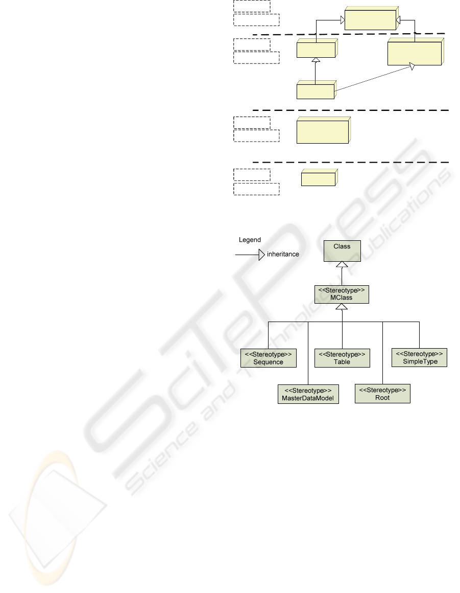
Figure 2: Part of the UML profile representing Master
Data Management metamodel.
Using UML extension mechanism enables us to
extend the UML formalism to our semantic. This
extension is done using stereotypes and tagged
values. Stereotypes are used to extend the semantic
of UML, to a particular domain, by the definition of
new types of element derived from existing ones.
We can see on the figure 2 that the stereotypes
(labelled <<Stereotypes>>) inherit from the element
Class of the UML metamodel. As a result, the
stereotypes will be instantiated from the metamodel
constructor in the same way as the element Class.
Tagged values specify keyword-value pairs of model
elements to set properties for existing elements or
for stereotypes. According to our profile, a model is
composed of stereotyped classes called
<<MClass>>. <<MClass>> is a generic class for the
concepts of our metamodel. The definition of these
MOF
Meta MetaModel
UML
MetaModel
Master Data
Management
MetaModel
UML Profile
Master Data
Management
Model
Data
Conform to
Conform to
specialises
Defines
LAYER M3
LAYER M2
LAYER M1
LAYER M0
Meta MetaModel
MetaModel
Model
Instance
ICEIS 2008 - International Conference on Enterprise Information Systems
462
stereotypes allows more semantics to be introduced,
out of the concepts defined in UML which will
enable us to define an XML model with an UML
diagram.
3 CASE STUDY
This section illustrates part of a model defined with
MDM-p and its equivalent in XML Schema. The
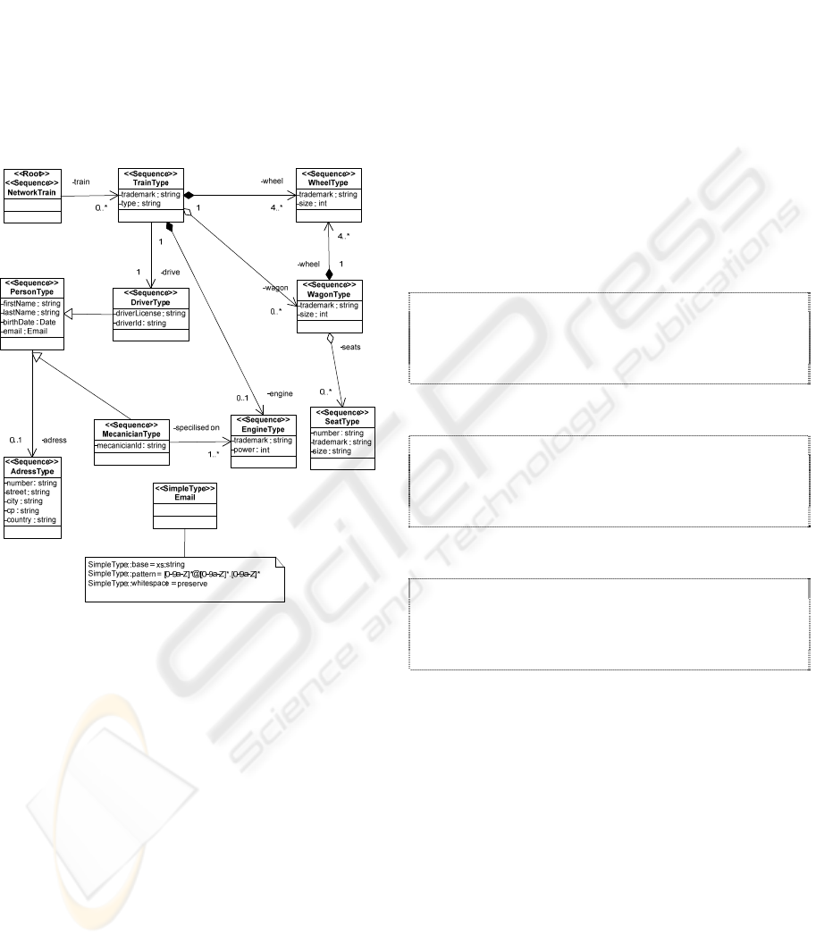
figure 3 represents the UML modeling of a XML
model defining a simplified train network.
Figure 3: Definition of an XML model with UML.
In this example, we have defined the concept
Train as composed of an engine, wheels (notion of
composition), being able to have wagons (notion of
aggregation) and having properties such as a type
and a trademark. We associate a driver of type
Person with a train. The concept Person defines
properties such as firstname, lastname and birthday.
We have also defined the property email
representing the use of a redefined type. The class
Email uses the stereotype <<SimpleType>>
indicating that it is a redefined type in the XML
Schema sense. The properties of this redefined type
are expressed in an UML annotation specifying
values for SimpleType::base, SimpleType::pattern
and SimpleType::whitespace. The root of the schema
is specified by the stereotype <<Root>>, applied to
the class NetworkTrain. The classes defined in this
model are also stereotyped <<Sequence>>. This
stereotype specifies that the corresponding class
represents a complex element of the type
<xs:sequence> in the XML Schema definition.
A part of the corresponding XML Schema model
is shown below:
<xs:element name="train" type="trainType"
minOccurs="0" maxOccurs="unbounded"/>
</xs:sequence>
</xs:complexType>
</xs:element>
<!--~~~~~~~~~~~~~~~~~~~~~~~~~~~~~~~ -->
<!--Class : trainType -->
<!--~~~~~~~~~~~~~~~~~~~~~~~~~~~~~~~ -->
<!--trainType -->
<xs:complexType name="trainType">
<xs:sequence>
<xs:element name="trademark"
type="xs:string"/>
<xs:element name="type"
type="xs:string"/>
<xs:element name="wagon" type="wagonType"
maxOccurs="unbounded">
<xs:annotation>
<xs:appinfo>
<osd:aggregation/>
</xs:appinfo>
</xs:annotation>
</xs:element>
<xs:element name="engine"
type="engineType">
<xs:annotation>
<xs:appinfo>
<osd:composition/>
</xs:appinfo>
</xs:annotation>
</xs:element>
<xs:element name="wheel" type="wheelType"
minOccurs="4" maxOccurs="unbounded">
<xs:annotation>
<xs:appinfo>
<osd:composition/>
</xs:appinfo>
</xs:annotation>
</xs:element>
<xs:element name="drive"
type="personType"/>
…
Using the UML formalism we are able to
introduce semantic constraints to XML models,
bringing more signification to relationships inside
models. By semantic constraints, we talk about
object features such as aggregation, composition,
generalisation and specialisation. It is not possible
explicitly with XML Schema to express such
constraints. Indeed, an aggregation can be
materialised with the XML Schema keyref
mechanism but the lyfe cycle of such relation is not
evidently expressed. We have then introduced these
features throught the mechanism of extension
suggested by the W3C. With our extensions (noted
<osd:composition>, <osd:aggregation> in the
previous code example) we can describe the
DESIGNING XML PIVOT MODELS FOR MASTER DATA INTEGRATION VIA UML PROFILE
463

semantic links between concepts. More precisely,
the concept Train is a composition of wheels,
engine, and an aggregation of wagons. These
semantic links have strong impacts on optimising
data. Indeed in our previous example the
composition implies that there cannot be instances of
the concept Engine without instances of the concept
Train. Deleting an instance of concept Train implies
that all dependent instances (Engine) will be
removed. So, the deletion process is optimised. In
the other hand, the aggregated instances (Wagon)
will not be deleted in the case of aggregation
between concepts.
Generalisation and specialisation relations are
used to factorise data. In the generalisation case,
common attributes are gathered in a general concept.
For example, attributes such as firstname and
lastname are common to the concepts driver and
mecanician. These two attributes are migrated to the
concept Person to factorise data, avoiding
duplication of their definition in the concepts driver
and mecanician.
4 CONCLUSIONS
We saw in this paper that we can facilitate
communication between people using a common
formalism, in our case using UML as an abstraction
of any technical language. UML is a powerful and
flexible modeling language and XML became a
standard for data interchange on the Web. The use of
these two technologies addresses interoperability
and a standard means of exchanging and defining
models. Therefore, we have shown how UML
profiles facilitate the definition of an XML Schema
model and fill the lack of semantic expressiveness.
Our follow-up work will consist of the
enrichment of MDM-p and the creation of a
complete data modeling language for the Master
Data Management module in the following two
ways: (i) a graphical language using UML modeling,
(ii) a specialised language using UML meta-
modeling. This language will take into account the
definition of constraints and the validation of models
using OCL (Object Constraint Language) (OMG,
2002) (Bazex, 2003).
REFERENCES
Abiteboul S., Cluet S., Ferran G., Rousset M.-C., 2002.
The Xyleme Project. Computer Networks 39.
Apvrille L., De Saqui-Sannes P., Khendek F., 2006.
TURTLE-P: A UML Profile for the Formal Validation
of critical and Distributed Systems. SoSym (Software
and System Modeling) Journal, Springer, ISSN 1619-
1366, pp. 1-18, July.
Bazex P., Bodeveix J-P., Millan T ., Le Camus C.,
Percebois C., 2003. Vérification de modèles UML
fondée sur OCL. INFORSID. Nancy, France. pp. 185-
200.
Garcia-Molina H., Papakonstantinou Y., Quass D.,
Rajaraman A., Sagiv Y., Ullman J., Widom J., 1995.
The STIMMIS approach to mediation: Data Models
and Languages. NGITS (Next Generation Information
Technologies and Systems), Naharia, Isreal, June 27-
29.
Greenfield J., 2001. UML Profile For EJB. Rational
Software Corp, May.
Lamolle M., and Zerdazi A., 2005. Intégration de Bases de
données hétérogènes par une modélisation
conceptuelle XML, In Conférence sur l’Optimisation
et les Systèmes d’Information (COSI’05), pp.216-227.
Ober I., Graf S., 2005. Timed annotations in UML
accepted to STTT, Int. Journal on Software Tools for
Technology Transfer Springer Verl.
OMG/MOF, 2000. Meta Object Facility (MOF)
Specification, OMG Document formal/2000-04-03,
http://www.omg.org/technology/documents/formal/mo
f.htm.
OMG, 2002. “CORBA specifications”.
http://www.omg.org/technology/documents/formal/pr
ofile_corba.htm.
OMG, 2002. Response to the UML 2.0 OCL.
http://www.omg.org/docs/ad/02-05-09.pdf
Orchestra Networks, 2000.
http://www.orchestranetworks.com
Pilone D., Pitman N., 2006. UML 2.0 in a Nutshell,
O’Reilly.
ICEIS 2008 - International Conference on Enterprise Information Systems
464
