
ROUND-TRIP ENGINEERING OF WEB APPLICATIONS
FOCUSING ON DYNAMIC MODELS
Yuto Imazeki, Shingo Takada
Graduate School of Science and Technology, Keio University
3-14-1 Hiyoshi, Kohoku-ku, Yokohama, Kanagawa 223-8522, Japan
Norihisa Doi
Faculty of Science and Engineering, Chuo University, 1-13-27 Kasuga, Bunkyo-ku, Tokyo 112-8551, Japan
Keywords:
Round-trip engineering, web application, sequence diagram, statechart, MVC.
Abstract:
Enterprise information systems take many forms, one of which is Web applications. The demand for rapid
development of such Web applications is becoming stronger, but there is still no good way. Round-trip engi-
neering is a software development method that iterates between the modeling phase and coding phase, allow-
ing for iterative and incremental development. However conventional tools only support static models such as
class diagrams. We thus propose a tool for round-trip engineering of Web applications that supports dynamic
models such as sequence diagrams and statecharts. We introduce a navigation model to model the navigation
between Web pages. This model is used to link the various diagrams as well as to generate source code. We
describe a case study to show the effectiveness of our tool.
1 INTRODUCTION
Enterprise information systems take many forms, one
of which is Web applications. Such Web applications
are becoming larger and more complex while the de-
mand for their rapid development is increasing. This
is further complicated by the fact that requirements
frequently change during (and even after) develop-
ment, in response to feedback from customers and
users. Thus, an iterative and incremental process is
efficient for developing Web applications.
To support iterative and incremental software de-
velopment, we focus on round-trip engineering which
is a software development method that iterates be-
tween forward and reverse engineering (Henriksson
and Larsson, 2003) (Medvidovic and A. Egyed, 1999)
(Sendall and Kuster, 2004). Developers generate
source code from models during forward engineering,
and generate models from code during reverse engi-
neering. In other words, they iterate between model-
ing and coding, resulting in a refinement of the mod-
els and code. During this iteration, the models and
code need to be kept consistent with each other.
Tools that support round-trip engineering include
(Borland, 2006) (IBM, 2006) (Omondo, 2006). How-
ever, their support is limited to class diagrams, i.e.,
they only support the consistency between class dia-
grams and code. They do not support dynamic mod-
els such as sequence diagrams and statecharts. Since
developers will often use models other than class dia-
grams, we need support for other types of models.
We thus propose a tool that supports round-trip
engineering that handles dynamic models and source
code. Our tool targets business logic development of
Web applications, and supports sequence diagrams,
statecharts and source code. In order to support dy-
namic models, we consider a major characteristic of
Web applications: Web applications are based on
pages. Users navigate among the various pages to
conduct tasks. When the users perform tasks, corre-
sponding logics are executed. Such information are
important and useful during development. We thus
propose a navigation model which contains informa-
tion concerned with page navigation. The navigation
model enables efficient iterative and incremental de-
velopment of Web applications.
In the rest of this paper, section 2 first presents re-
lated works and points out issues. Section 3 proposes
our tool that supports round-trip engineering between
dynamic models and source code. Section 4 discusses
our approach through a case study. Section 5 makes
concluding remarks.
228
Imazeki Y., Takada S. and Doi N. (2008).
ROUND-TRIP ENGINEERING OF WEB APPLICATIONS FOCUSING ON DYNAMIC MODELS.
In Proceedings of the Tenth International Conference on Enterprise Information Systems - ISAS, pages 228-233
DOI: 10.5220/0001690802280233
Copyright
c
SciTePress

2 SUPPORTING ROUND-TRIP
ENGINEERING
Many commercial tools support round-trip engineer-
ing, including Together (Borland, 2006), Rational
Software Modeler (IBM, 2006), and EclipseUML
(Omondo, 2006). They convert between class dia-
grams and code, keeping them consistent with each
other. However, they only support class diagrams
which is a static model, and do not support dynamic
models such as sequence diagrams and statecharts
1
.
Since we usually model with both static models
and dynamic models, we need support for both types.
If there are multiple types of models, we also need
to consider generation between them. Thus, we need
to support between models,from model to code, and
from code to model. We next describe related work
on each conversion type.
2.1 Between Models
Hasegawa et al proposed a tool that converts between
sequence diagrams and statecharts (Hasegawa et al.,
2004). They used MSC, which is composed of se-
quence diagrams (bMSC’s) and hMSC. hMSC con-
nects bMSC’s to show the process flow between se-
quence diagrams. The sending and receiving of mes-
sages in a bMSC corresponds to a state transition.
They use this correspondence to convert each bMSC
to a statechart. These statecharts are then combined
using information from the hMSC.
Changes in statechart are reflected to the sequence
diagram by specifying a bMSC which corresponds to
those changes. Their tool then integrates this bMSC
into the hMSC. Note that this bMSC must be specified
by the developer, and they only support addition of
new transitions to the statechart.
2.2 From Model to Code
The statechart in UML 2.1 (OMG, 2007) takes the
Executable UML approach (Mellor and Balcer, 2002)
(Starr, 2002), where executable source code (not just
template code) can be generated. ExecutableUML in-
troduces action language (Action Semantics) (OMG,
2007) which is used to describe actions such as mes-
sage sending which occur within a state. Each state
corresponds to a method in source code, and the ac-
tion description corresponds to the method’s body.
Using this relation, source code can be generated from
statechart. However, this is not trivial, because we
must specify the action description in detail to gener-
ate completely executable code.
1
Together has limited support for sequence diagrams.
2.3 From Code to Model
Tonella et al proposed an approach to generate se-
quence diagrams from code through static analysis
(Tonella and Potrich, 2003). Their method ana-
lyzes code and creates an Object Flow Graph (OFG)
which expresses the generation and substitution of
each object. By performing flow inside the OFG, their
method generates a sequence diagram of the method.
In order to apply Tonella’s approach to round-trip
engineering, we need to specify all methods that are
targeted for generating sequence diagrams. Further-
more, their approach generates each sequence dia-
gram separately. Thus, information corresponding to
hMSC cannot be generated, and we cannot generate
statecharts.
3 ROUND-TRIP ENGINEERING
WITH DYNAMIC MODELS
We propose a tool that supports round-trip engineer-
ing, focusing on dynamic models to develop business
logic of Web applications. We first give an overview
of our tool. We then describe the navigation model.
Finally, we describe the generation algorithms.
3.1 Overview
A Web application typically consists of business
logic, page, and navigation. Each corresponds to a
module in the MVC (Model, View, Controller) pattern
(Krasner and Pope, 1988). This pattern has the feature
that the Controller has information on how the Model
is executed, i.e., the dynamic aspects of the Model.
Our tool targets the business logic of MVC pattern
based Web applications. We also introduce a navi-
gation model to model the navigation flow, and this
is used during the generation process. Our tool has
the following functions: (1) generate statecharts from
sequence diagrams, (2) generate sequence diagrams
from statecharts, (3) generate code from statecharts,
(4) generate sequence diagrams from code, and (5)
generate controller code from navigation model. It
also supports UML class diagrams, but we omit its
details due to space.
In our tool, sequence diagrams and statecharts can
be considered as one type of model, because they can
be converted between each other. Thus, although our
tool can not directly generate source code from se-
quence diagram, it can generate source code from se-
quence diagram by first generating statecharts. Sim-
ilarly, our tool can generate statechart from source
code via sequence diagram.
ROUND-TRIP ENGINEERING OF WEB APPLICATIONS FOCUSING ON DYNAMIC MODELS
229
3.2 Navigation Model
The navigation model shows the transitions between
pages and actions caused by events. A page corre-
sponds to a Web page. An action corresponds to a
business logic, specifically a sequence diagram. An
event corresponds to a request sent by a page.
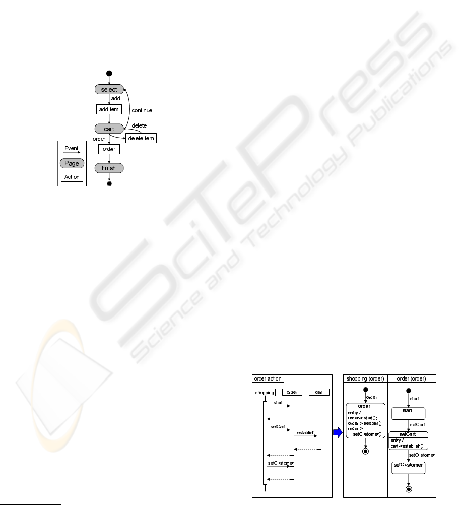
Fig.1 shows the navigation model for an online
shopping system. When the application is at the
select
page and an
add
event occurs, the
addItem
action is executed, and the page becomes
cart
. The
continue
event causes no action to occur from the
select
page. Although not shown in this example, it
is also possible to show arguments in events, branch-
ing after events, etc.
Figure 1: Navigation model for online shopping system.
Our tool generates controller code from the navi-
gation model. A receiver class is specified as a prop-
erty of the navigation model, so that the controller
code can call business logic. Specifically, the con-
troller code calls the specified receiver class’s method
whose name is the same as the action name
2
.
3.3 Sequence Diagram to Statechart
To generate statechart from sequence diagram, our
tool uses a similar approach to Hasegawa’s approach
(Hasegawaet al., 2004). Although the sending and re-
ceiving of messages correspond to state transitions in
Hasegawa’s approach, we only associate message re-
ceipt to state transition. We also use action language
in the statechart to handle message sending, branch-
ing, and looping in the sequence diagram.
Statechart is generated as follows:
Step 1: Generate a “Small” Statechart. Our tool
analyzes each sequence diagram from its beginning.
When a message is found, we add a new state to the
receiving object’s statechart, We then add an action
description of the message to the current state of the
sending object. When a branch or loop is found, our
2
See Section 3.7 for detail
tool generates a statechart inside this structure, and
generates a transition to the generated statechart(s).
Action description is also added to the state of the ob-
ject sending the message.
Fig. 2 shows an example of “small” statecharts
generated from a sequence diagram (We only show
shopping
and
order
due to space). The sending
of message
start
corresponds to the action descrip-
tion
order->start()
in the
order
state of
shopping
statechart; its reception corresponds to transition
start
in the
order
statechart.
Step 2: Create hMSC from Navigation Model.
Our tool generates an hMSC-like statechart (which
we call hMSC for convenience) by removing pages
from the navigation model.
Step 3: Combine “Small” Statecharts to Construct
Final Statechart. Our tool completes the statechart
by replacing each action in the hMSC with its corre-
sponding “small” statechart.
Fig. 3 shows an example of combining statecharts.
(a) is an hMSC created in step 2, and (b) shows small
statecharts created in step 1. These small statecharts
are combined according to step 3 resulting in (c).
3.4 Statechart to Sequence Diagrams
To generate sequence diagrams from statecharts, our
tool traces the action description as follows:
Step 1: Determine the Starting Points of Trace.
Our tool uses the navigation model to decide on the
starting points. We designate as starting points to be
methods in the receiver class whose names are the
same as actions in the navigation model.
Step 2: Trace Action Description. Our tool traces
action description recursively from the starting point.
When our tool finds a message in an action descrip-
tion, it inserts that message into the sequence diagram
Next, our tool searches for the state corresponding to
Figure 2: Sequence Diagram to Small Statechart.
ICEIS 2008 - International Conference on Enterprise Information Systems
230

Figure 3: Combining Statechart.
Figure 4: Statechart to Sequence Diagram.
the message in the statechart, and continues the anal-
ysis. When our tool finds a branch or loop structure,
our tool inserts a branch or loop structure into the
sequence diagram, and inserts subsequent messages,
branches, and loops until the structure is closed.
Fig. 4 shows an example of generating a sequence
diagram which corresponds to action
order
in Fig.
1. We assume that
shopping
class was specified as
the receiver of action
order
in the navigation model.
Thus, our tool starts analyzing the action description
in the
order
state of
shopping
statechart. First, our
tool finds that message
start
is sent to object
order
.
Our tool inserts a
start
message in the sequence di-
agram, and continues the analysis in the
start
state.
Because there are no actions in this state, the analysis
returns to
order
state. Our tool continues the anal-
ysis until the end of the
order
state, resulting in the
sequence diagram shown in the right side of Fig. 4.
3.5 Statechart to Source Code
In our tool, each statechart corresponds to a class,
and a state corresponds to a method. It is impossi-
ble to generate complete source code from statecharts
unless the action description is described in detail.
Therefore, our tool generates source code template
when source code does not exist (i.e., initial gener-
ation of code from statechart). In template code gen-
eration, our tool first generates a class definition for
each statechart. and a method definition for each state
in the statechart. Furthermore, our tool inserts action
description into the method body.
When source code already exists, our tool com-
pares the statecharts with existing code. This is done
by first generating statecharts from the source code
via sequence diagrams
3
. The resulting statecharts
are compared with the existing statecharts. Our tool
checks for corresponding states based on the state
name. If a corresponding state exists, then our tool
compares their action descriptions. The algorithm for
comparing action language descriptions is very sim-
ple because we can only describe message sending,
branch and loop with action language. Each statement
in the action description is compared one by one. If
there are any differences, it is reported to the user.
3.6 Source Code to Sequence Diagrams
The generation of sequence diagrams from source
code is similar to generating sequence diagram from
statechart. Our tool statically analyzes source code
instead of action descriptions.
The message destination’s object name in action
description corresponds to the object name in se-
quence diagrams, butthis correspondencemay not ex-
ist for source code because of aliasing. Therefore we
create OFG based on Tonella’s approach (Tonella and
Potrich, 2003). Although Tonella’s approach starts
analysis from the main method, it is difficult to create
a complete OFG from the main method, because the
application’s behavior will depend on the user. Fur-
thermore, Web applications normally do not have a
main method. Therefore, our tool starts its analysis
with each action. However, it is not clear where an
object is instantiated, if instantiation is done in differ-
ent actions. In such a case, our tool integrates OFG’s
to determine where instantiation occurs.
Unfortunately, it is difficult to integrate OFG’s
when the object to which a variable refers changes
depending on the execution path. Therefore, we place
a constraint that the object to which a field in a class
refers does not change.
The generation algorithm is as follows:
Step 1: Determine the Starting Points of Trace.
Our tool uses the navigation model to decide on the
starting points of traces in the same way as generat-
ing a sequence diagram from statecharts.
3
See Section 3.6 for generating sequence diagrams.
ROUND-TRIP ENGINEERING OF WEB APPLICATIONS FOCUSING ON DYNAMIC MODELS
231
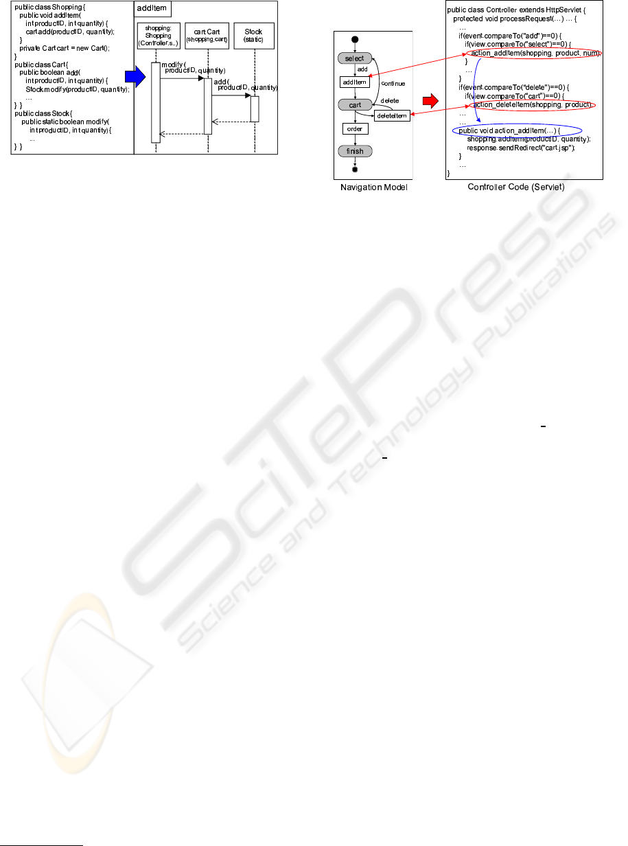
Figure 5: Source Code to Sequence Diagram.
Step 2: Trace Source Code. Our tool traces source
code recursively from each starting point. Our tool
generates an OFG, and an initial sequence diagram
where the objects have yet to be determined.
Step 3: Integrate OFG’s. Our tool searches for
OFG’s which do not include instantiation. If such an
OFG is found, our tool searches for a node
4
whose
description is the same as the root node from other
OFGs, and combines with the found node.
However, when multiple edges are found, it is dif-
ficult to judge which edge to connect. Therefore, as
described above, we assume that each field refers to
the same object at all time.
Step 4: Determine Objects in Sequence Diagram.
For all objects in the sequence diagram, our tool
searches for corresponding nodes in the OFG’s, and
replaces the object name in the sequence diagram
with the root node of the OFG.
Fig. 5 shows an example of generating a sequence
diagram for action
addItem
in Fig. 1. Each method
call corresponds to a message in the sequence dia-
gram, and each method argument corresponds to an
argument in the corresponding message. The ob-
ject name in the sequence diagram is complemented
by name and type at instantiation. For example,
cart:Cart (shopping.cart)
denotes a
cart
ob-
ject which is instantiated as an instance of the
Cart
class in the method
shopping.cart()
, and
Stock
(static)
means
Stock
is a static class.
3.7 Controller Code Generation
The controller code consists of code for transitioning
to a page or action based on the received event and the
current view. To call an action from controller code,
we use the receiver class that is specified in the navi-
gation model. The receiver class’s method name is the
4
A node represents a variable which refers to an object
Figure 6: Navigation model to controller code.
same as the action name that is called from the con-
troller. The controller instantiates the receiver class
during initialization of the controller, and stores the
instance in a session (
HttpSession
). In other words,
when a user first accesses a Web application, the re-
ceiver class is instantiated and stored. In the future,
the receiver is loaded from the session.
Fig. 6 shows an example. The controller is im-
plemented as a subclass of the
HttpServlet
class. In
processRequest
method, the event and view deter-
mine which action to take. For each action, our tool
has generated methods such as
action addItem
for
each action. The method call
shopping.addItem()
in
action addItem
is a method call to a receiver
class’s instance.
4 DISCUSSION
We discuss a case study of developing an online shop-
ping system. A developer took an iterative and in-
cremental approach, first developing a prototype. He
then added various changes to the prototype. The re-
sulting system had 23 actions with about 4000 LOC.
Each generation required at most one second, when
our tool was used on a computer having Intel(R) Pen-
tium(R) 4 CPU 3.40GHz with 1024MB RAM.
4.1 Example Scenario
The developer first designed the overall workflow of
the system using the navigation model. Then, he de-
signed each action and continuously refined the se-
quence diagrams and statecharts using the round-trip
engineering capability of our tool. As a result, he
was able to examine the validity and impact of the
change not just with the sequence diagram but also
with the statechart. After finishing modeling, he gen-
erated source code from the statechart, and manually
ICEIS 2008 - International Conference on Enterprise Information Systems
232

completed the source code. Finally, he generated con-
troller code from the navigation model.
We asked various modifications to be made to the
prototype. Because our tool makes it possible to syn-
chronize all models automatically, modifications were
made incrementally, synchronizing all models each
time. When functions are added and requirements
change, he can return to the modeling phase, mod-
ify the software design, and then easily reflect the
changes to the source code. Furthermore, he can mod-
ify source code directly, and automatically update the
models. Therefore, the developer can choose how to
modify the application, i.e., through the sequence di-
agrams, statecharts, or source code.
4.2 Discussion
When generating statechart from sequence diagram,
information is not lost because all elements in a se-
quence diagram has a correspondingelement in a stat-
echart. On the other hand, when generating sequence
diagram from statechart, our tool analyzes action de-
scriptions and not states or transitions. Thus, when
adding or removing states or transitions, we must add
or remove the corresponding action description. To
solve this problem, we may need functions such as the
verification of whether a statechart has enough action
descriptions
When analyzing source code, we assume that each
field refers to the same object at all time. As long
as this constraint is satisfied, information is not lost
when generating sequence diagram from source code
because our tool identifies object using integrated
OFG. However, if there is a violation, our tool can-
not analyze the code correctly. In this case, it is nec-
essary to exclude the violating object from analysis.
The analysis can still continue correctly as long as the
excluded object does not send a message to other ob-
jects, because an object with no message sending does
not affect other objects.
Since our tool needs the navigation model for gen-
eration, application development with our tool should
always start from the very beginning. However, a de-
veloper can use our tool on an existing application if
he first creates its navigation model. The controller
and logic does not need to be clearly separated, but
each logic needs to start with a call to an arbitrary
method. This makes it possible to create a navigation
model using a receiver class as a proxy. However, our
tool cannot generate controller code from this type
of navigation model, and it is not possible to verify
whether the navigation model is correct.
5 CONCLUSIONS
We proposed a tool that supports round-trip engineer-
ing that handles dynamic models and source code.
Our tool targets business logic development of Web
applications, and supports sequence diagrams, state-
charts and source code. We also introduce a navi-
gation model to model the navigation flow, and this
is used during the generation process. Our tool also
takes the navigation model and generates controller
code. Our tool make possible efficient iterative and
incremental development of Web applications.
Future work includes the following: (1) verifica-
tion of statechart described in Section 4.2, (2) removal
of the constraint on source code analysis, and (3) co-
ordination with existing MVC based Web application
development frameworks.
REFERENCES
Borland (2006). Borland together technologies.
http://www.borland.com/us/products/together/.
Hasegawa, H., Takada, S., and Doi, N. (2004). Supporting
the iterative development of sequence diagrams and
statecharts. In Proc. of the 8th IASTED Int’l Conf. on
Software Engineering and Applications, pp.736-742.
Henriksson, A. and Larsson, H. (2003). A definition
of round-trip engineering. In Technical Report,
http://www.ida.liu.se/˜andhe/re.pdf.
IBM (2006). Rational software modeler. http://www-
306.ibm.com/software/rational/.
Krasner, G. E. and Pope, S. T. (1988). A description of the
model-view-controller user interface paradigm in the
smalltalk-80 system. In Journal of Object Oriented
Programming, Vol.1, No.3, pp.26-49.
Medvidovic, N. and A. Egyed, D. S. R. (1999). Round-trip
software engineering using uml: From architecture to
design and back. In Proc. of the 2nd Workshop on
Object-Oriented Reengineering, pp.1-8.
Mellor, S. J. and Balcer, M. J. (2002). Executable UML - A
Foundation for Model-Driven Architecture. Addison
Wesley.
OMG (2007). Unified modeling language (uml), version
2.1.1. http://www.omg.org/.
Omondo (2006). Eclipseuml. http://www.eclipseuml.com/.
Sendall, S. and Kuster, J. (2004). Taming model round-trip
engineering. In Proc. of Workshop on Best Practices
for Model-Driven Software Development.
Starr, L. (2002). Executable UML - How To Build Class
Models. Prentice-Hall, Inc.
Tonella, P. and Potrich, A. (2003). Reverse engineering of
the interaction diagrams from c++ code. In Proc. of
the Int’l Conf. on Software Maintenance, pp.159-168.
ROUND-TRIP ENGINEERING OF WEB APPLICATIONS FOCUSING ON DYNAMIC MODELS
233
