
Distributed Mission and Contingency Management for
the DARPA Urban Challenge
Tichakorn Wongpiromsarn and Richard M. Murray
Division of Engineering and Applied Science
California Institute of Technology, Pasadena, CA, U.S.A.
Abstract. We present an approach that allows mission and contingency man-
agement to be achieved in a distributed and dynamic manner without any central
control over multiple software modules. This approach comprises two key el-
ements: a mission management subsystem and a planning subsystem based on
a Canonical Software Architecture (CSA). The mission management subsystem
works in conjunction with the planning subsystem to dynamically replan in reac-
tion to contingencies. The CSA provides for consistency of the states of all the
software modules in the planning subsystem. System faults are identified and re-
planning strategies are performed distributedly in the planning and the mission
management subsystems through the CSA. The approach has been implemented
and tested on Alice, an autonomous vehicle developed by the California Institute
of Technology for the 2007 DARPA Urban Challenge.
1 Introduction
One of the major challenges in urban autonomous driving is the ability of the system to
reason about complex, uncertain, spatio-temporal environments and to make decisions
that enable autonomous missions to be accomplished safely and efficiently, with reac-
tive replanning in case of contingencies. Due to the complexity of the system and a wide
range of environments in which the system must be able to operate, an unpredictable
performance degradation of the system can quickly cause critical system failure. In a
distributed system such as Alice, an autonomous vehicle developed by the California
Institute of Technology for the 2007 DARPA Urban Challenge, performance degra-
dation of the system may result from changes in the environment, hardware failures,
inconsistencies in the states of different software modules, and faulty behaviors of a
software module. To ensure safety and mission success, there is a need for the system
to be able to properly detect and respond to these unexpected events which affect the
vehicle’s operational capabilities.
Mission and contingency management is often achieved using a centralized ap-
proach where a central module communicates with nearly every software module in
the system and directs each module sequentially through its various modes in order to
recover from failures. Examples of such a central module are the behavior manage-
ment module of the TerraMax Autonomous Vehicle [1] and the supervisory controller
(SuperCon) module of Alice previously developed for the 2005 DARPA Grand Chal-
lenge [2]. A drawback of this approach is that the central module usually has so much
Wongpiromsarn T. and M. Murray R. (2008).
Distributed Mission and Contingency Management for the DARPA Urban Challenge.
In Proceedings of the 2nd International Workshop on Intelligent Vehicle Control Systems, pages 19-29
Copyright
c
SciTePress

functionality and responsibility that it easily becomes unmanageable and error prone as
the system gets more complicated. In fact, Team Caltech’s failure in the 2005 DARPA
Grand Challenge was mainly due to an inability of the SuperCon module to reason and
respond properly to certain combinations of faults in the system [2]. This resulted from
the difficulty in verifying this module due to its complexity.
The complexity and dynamic nature of the urban driving problem make centralized
mission and contingency management impractical. A mission management subsystem
and a planning subsystem based on a Canonical Software Architecture (CSA) [3] have
therefore been developed to allow mission and contingencymanagement to be achieved
in a distributed manner. The mission management subsystem comprising the mission
planner, the health monitor and the process control modules works in conjunction with
the planning subsystem (the trajectory planner, the follower and the drive control) to
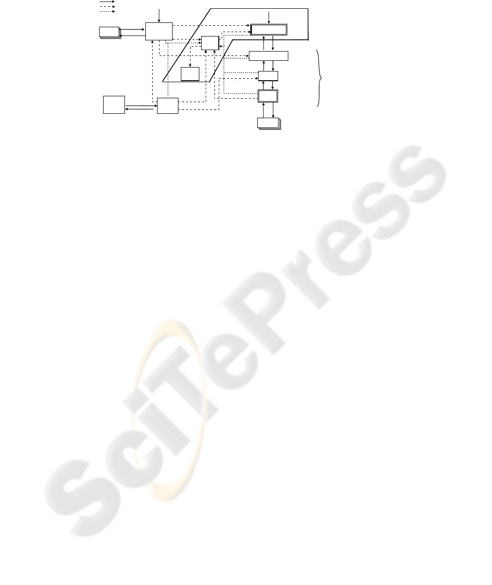
dynamically replan in reaction to contingencies. As shown in Figure 1, the health mon-
itor module actively monitors and estimates the health of the hardware and software
components to dynamically assess the vehicle’s operational capabilities throughout the
course of mission. It communicates directly with the mission planner module which re-
plans the mission goals based on the current vehicle’s capabilities. The process control
module uses the health estimates of individualsoftware modules to automatically restart
a software module that quits unexpectedly and a software module that identifies itself
as unhealthy. An unhealthy hardware component is power-cycled by the software that
communicates with it. The CSA providesfor consistency of the states of all the software
modules in the planning subsystem. System faults are identified and replanning strate-
gies are performed distributedly in the planning and the mission management subsys-
tems through the CSA directive/responsemechanism. Together these mechanisms make
the system capable of exhibiting a fail-operational/fail-safe and intelligent responses to
a number different types of failures in the system.
Related work includes a holistic contingency management technology [4], a Mis-
sion Effectiveness and Safety Assessment (MENSA) technology [5], real-time fault
detection and situational awareness [6], the high level controller of the Intelligent Off-
Road Navigator [7] and a model-based approach [8]. These approaches rely on having
a subsystem, similar to our mission management subsystem, capable of monitoring and
assessing unexpected, mission-related events that affect the overall system operation
and mission success. This subsystem may also be capable of suggesting a new strategy
or operation mode for the planning subsystem or reconfiguring the system in response
to these events. The CSA, however, is intended to facilitate these responsibilities of
the mission management subsystem. By exploiting the hierarchical structure and in-
tegrating the directive/response mechanism into the planning subsystem, the mission
management subsystem can assess most of the mission-related events by only reason-
ing at the level of failure or completion of its directives and the health of the hardware
and software components.
The contributions of this paper are: (1) a framework for integrating mission and
contingencymanagement into a planning system so that it can be achieved distributedly
and dynamically; (2) a complete implementation on an autonomous vehicle system ca-
pable of operating in a complex and dynamic environment; and (3) an evaluation of
the approach from extensive testing and some insight into future research directions.
Sensing and
Mapping
Subsystem
Health
Monitor
Applanix
(GPS and
IMU)
Vehicle
State
Estimator
Follower
Segment-level goal
Trajectory
Actuator command
Actuator command
(including reset
command)
Connect/
disconnect
command
Vehicle capability
Actuator health
Vehicle state
estimation
health
Connect/
disconnect
command
Sensing health
World map
Local map
Mission Data File
Route Network
Definition File
Vehicle
state
Vehicle state
Directive/response
State knowledge
Sensors
Response
Response
Trajectory Planner
Response
Response
Response
Response
Actuators
Mission Planner
Process
Control
Process health
Drive
Control
Planning Subsystem
Mission Management
Subsystem
health
estimates
of all the
modules
Fig.1. Alice’s mission management and planning subsystems in the Canonical Software Archi-
tecture. Boxes with double lined borders are subsystems that will be broken up into multiple CSA
modules.
The remainder of this paper is organized as follows. Section 2 introduces the concept
of the Canonical Software Architecture. Section 3 describes the mission management
subsystem in more detail. Section 4 explains how system faults can be identified and
handled distributedly through the CSA. Section 5 presents the results from the 2007
DARPA Urban Challenge’s National Qualifying Event and provides a discussion about
the advantages and disadvantages of the approach. Section 6 concludes the paper and
discusses some future work.
2 Canonical Software Architecture
In many complex systems, the software modules that make up the planning system are
responsible for reasoning at different levels of abstraction. Hence, the planning system
can be decomposed into a hierarchical framework. A Canonical Software Architecture
has been developed to support this decomposition and separation of functionality, while
maintaining communication and contingency management. This architecture builds on
the state analysis framework developed at the Jet Propulsion Laboratory (JPL) and takes
the approach of clearly delineating state estimation and control determination as de-
scribed in [9], [10], [11] and [12]. To prevent the inconsistency in the states of different
software modules due to the inconsistency in the state knowledge, we require that there
is only one source of state knowledge although it may be provided in different abstrac-
tions for different modules.
There are two types of modules in CSA: estimation modules and control modules.
For modularity, each software module in the planning subsystem may be broken down
into multiple CSA modules. An example of the planning subsystem in CSA we have
implemented on Alice is shown in Figure 1. An estimation module estimates the sys-
tem state and provides an abstraction of the system state for the corresponding con-
trol module(s). A control module gets inputs, performs actions based on the inputs,
and delivers outputs. As shown in Figure 2, the inputs consist of state information,
directives/instructions (from other modules wishing to control this module) and re-

Arbitration
Control Tactics
Merged directive: start/end conditions,
parameterized constraints,
performance criteria
Response:
completed/
failed
Initialize
A generic
control module
Directive: start/end conditions,
parameterized constraints,
performance criteria, priority
Response:
accepted/rejected,
completed/failed
State information
Directive, state
Tactic
Controlling module
Same interface with
other controlling modules
Controlled module and/or Estimator or Hardware
Directives
Response
Fig.2. A generic control module in the Canonical Software Architecture.
sponses/status reports (from other modules receiving instructions from this module).
The outputs are the same type as the inputs, but in the reverse direction (status reports
from this module and directives/instructions for other control modules).
For each directive that a control module is designed to accept, the following must
be specified: (1) entry condition; (2) exit condition; (3) constraints that must be satis-
fied during the execution of the directive; and (4) performance criteria (performance or
other items to be optimized). The entry and exit conditions define, respectively, what
must be true before starting to execute this directive and what must be true to complete
the execution of this directive. For each directive received, a response which indicates
rejection, acceptance, failure or completion of the directive and the reason for rejection
or failure must be reported to the source of the directive. Rejection or failure of a di-
rective occurs when the entry or exit condition is not readily achievable, the deadlines
aren’t met, or one of the constraints cannot be satisfied.
A CSA module consists of three components: Arbitration, Control and Tactics. It
communicates with its neighbors through directives and responses, as shown in Figure
2. Arbitration is responsible for (1) managing the overall behavior of the control module
by issuing a merged directive, computed from all the received directives, to the Control;
and (2) reporting failure, rejection, acceptance and completion of a received directive
to the Control of the issuing control module. We have implemented a simple arbitration
scheme, similar to that of the subsumption architecture [13], where the merged direc-
tive is simply the received directive with the highest priority. As a future work, one can
implement a more complicated arbitration scheme that involves dealing with multiple
received directives simultaneously. Control is responsible for (1) computing the output
directives to the controlled module(s) or the commands to the hardware based on the
merged directive, received responses and state information; and (2) reporting failure
and completion of a merged directive to the Arbitration. Tactics provides the core func-
tionality of the control module and is responsible for providing the logic used by the
Control for computing output directives.
3 Mission Management Subsystem
3.1 Health Monitor and Vehicle Capabilities
The health monitor module is an estimation module that continuously gathers the health
of the software and hardware (GPS, sensors and actuators) components of the vehicle

and abstracts the information about these devices into a form usable for the mission
planner. This form can most easily be thought of as vehicle capability. For example,
we may start the mission with perfect functionality, but somewhere along the line lose
a right front sensor. The intelligent choice in this situation would be to try to limit the
number of left turns at intersection due to the inability to assess oncoming traffic from
the right and slow down the vehicle. Another example arises if the vehicle becomes
unable to shift into reverse. In this case we would not like to purposely plan paths that
require a three-point turn.
From the health of the sensors and sensing modules, the health monitor estimates
the sensing coverage. The information about sensing coverage and the health of the GPS
unit and actuators allow the health monitor to determine the following vehicle capabili-
ties: (1) turning right at intersection; (2) turning left at intersection; (3) going straight at
intersection; (4) nominal driving forward; (5) stopping the vehicle; (6) making a three-
point turn; (7) driving in an unstructured region; and (8) navigation in unmapped areas.
3.2 Mission Planner
The mission planner module receives a Mission Data File (MDF) that is loaded before
each mission, vehicle capabilities from the health monitor module, position of obsta-
cles from the mapper module and status reports from the trajectory planner module and
sends segment-level goals to the trajectory planner module. A segment-level goal spec-
ifies the road/zone Alice has to navigate and the constraints, represented by the type
of segment (road, zone, off-road, intersection, U-turn, pause, backup, end of mission)
which basically defines a set of traffic rules to be imposed during the execution of this
goal.
The mission planner is broken up into one estimation and two CSA control modules:
the traversibility graph estimator,the mission control and the route planner. The mission
control module has three main functions: (1) computing mission goals which specify
how Alice will satisfy the mission specified in the MDF; (2) based on the vehicle ca-
pabilities, determining conditions (including the maximum speed) under which we can
safely continue the mission; and (3) detecting the lack of forward progress and replan-
ning the mission goals accordingly.The route planner module determines segment-level
goals to satisfy the mission goals based on the traversibility graph which represents the
connectivity of the route network and is determined by the traversibility graph estimator
module. Since vehicle capabilities are also taken into account in the determination of
the mission goals and the traversibility graph, for example, if the capability for making
a left turn decreases due to the failure of the right front sensor, the route involving the
least number of these maneuvers will be preferred or if the vehicle is not able to shift
into reverse, routes that require a three-point turn will be avoided.
4 Fault Handling in the Planning Subsystem
In the CSA framework, fault handling is embedded into all the modules and their com-
munication interfaces in the planning subsystem hierarchy. Each module has a set of
different control strategies which allow it to identify and resolve faults in its domain

and certain types of failures propagated from below. If all the possible strategies fail,
the failure will be propagated up the hierarchy along with the associated reason. The
next module in the hierarchy will then attempt to resolve the failure. This approach al-
lows each module to be isolated so it can be tested and verified much more fully for
robustness.
Trajectory Planner. The trajectory planner accepts directives from the mission planner
module and generates trajectories for Alice to follow. It comprises four components:the
logic planner, the path planner, the velocity planner and the predictor. The logic plan-
ner guides the vehicle at a high level by determining the current situation and coming
up with an appropriate planning problem (or strategy) to solve. The path planner is re-
sponsible for finding a feasible path, subject to the constraints imposed by the planning
problem. If such a path cannot be found, an error will be generated. Since Alice needs
to operate in both structured and unstructured regions, we have developed three types of
path planner to exploit the structure of the environment: the rail planner (for structured
regions such as roads, intersections, etc), the off-road rail planner (for obstacle fields
and sparse waypoint regions) and the clothoid planner (for parking lots and obstacle
fields). All the maneuvers available to the rail planner are pre-computed; thus, the rail
planner may be too constraining. To avoid a situation where Alice gets stuck in a struc-
tured region (e.g. when there is an obstacle between the predefined maneuvers), the
off-road rail planner or the clothoid planner may also be used in a structured region.
This decision is made by the logic planner. The velocity planner takes the path from
the path planner and the planning problem from the logic planner and generates a time
parameterized path, or trajectory. The predictor is responsible for predicting the future
location and behavior of other vehicles.
The logic planner is responsible for fault handling inside the trajectory planner.
Based on the error from the path planner and the follower, the logic planner specifies
a different planning problem such as allowing passing or reversing, using the off-road
rail planner, or reducing the allowable distance from obstacles. The logic for dealing
with these failures can be described by a two-level finite state machine (FSM). First,
the high-level mode (road region, zone region, off-road, intersection, U-turn, failed and
paused) is determined based on the directive from the mission planner and the current
position. Each of the high-level modes can be further decomposed to completely spec-
ify the planning problem described by the drive state, the allowable maneuvers, and the
allowable distance from obstacles.
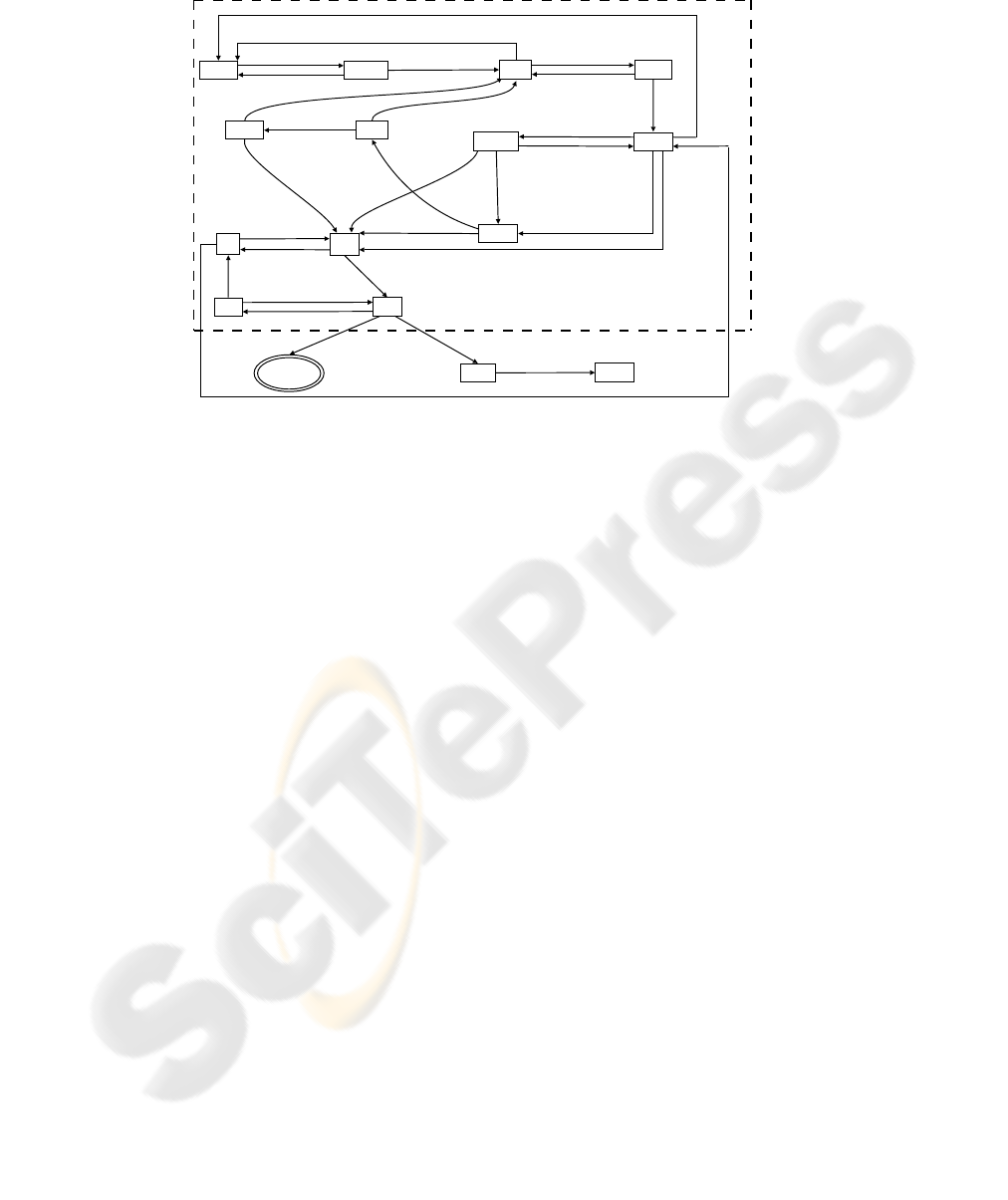
– Road Region, Zone Region and Off-Road. The logic planner transitions to the
road region, zone region or off-road mode when the type of segment specified by the
mission planner is road, zone or off-road, respectively. The modes and transitions
for the road region mode are shown in Figure 3. In the zone region and the off-road
modes, passing and reversing are allowed by default. For the zone region mode, the
clothoid planner is the default path planner and the trajectory is planned such that
Alice will stop at the right distance from the closest obstacle, so the only decision
that needs to be made by the logic planner is the allowable distance from obstacles
For the off-road mode, the drive state (drive or stop) also needs to be determined.
As a result, only three and six modes are necessary within the zone region mode
OFF-ROAD
mode
DR,NP,S STO,NP,S
no collision-free path exists
Alice has been stopped for long
enough and there is an obstacle
in the vicinity of Alice
passing finished or obstacle disappeared
DR,P,S STO,P,S
no collision-free path exists
collision-free path is found
no collision-free path exists
and the number of times Alice
has switched to the DR,P,R
state near the current position
is less than some threshold
DR,PR,S
no collision-free path exists and the
number of times Alice has switched
to the DR,P,R state near the current
position is less than some threshold
collision-free path is found
STO,PR,S
BACKUP
no collision-free
path exists and
there is more
than one lane
no collision-free
path exists and
there is only
one lane
backup finished
or failed and the
number of times Alice
has switched to BACKUP
is less than some threshold
DR,P,SSTO,P,S
no collision-free path exists
collision-free path is found
collision-free path is found
no collision-free
path exists
no collision-free path exists and the number
of times Alice has switched to the DR,P,R
state near the current position exceeds some
threshold and there is more than one lane
no collision-free path exists and the number of times Alice has switched to the DR,P,R
state near the current position exceeds some threshold and there is only one lane
STO,A
backup finished or failed and the
number of times Alice has switched
to BACKUP exceeds some threshold
DR,A
no collision-free path exists
no collision-free path exists
collision-free path is found
collision-free path is found
collision-free path
with DR,A is found
DR,B
STO,B
no collision-free path exists
collision-free path is found
no collision-free path exists
and there is more than one lane
collision-free path with DR,P,R is found
no collision-free path exists
and there is only one lane
passing finished or obstacle disappeared
FAILED
PAUSED
ROAD REGION
Fig.3. The logic planner FSM for the road region. Each mode defines the drive state (DR ≡ drive,
BACKUP ≡ reverse, and STO ≡ stop for obstacles), the allowable maneuvers (NP ≡ no passing
or reversing allowed, P ≡ passing allowed but reversing not allowed, PR ≡ both passing and
reversing allowed), and the minimum allowable distance from obstacles (S ≡ safe or nominal, A
≡ aggressive, and B ≡ bare or very aggressive).
and the off-road mode, respectively. The transitions can be easily deduced from
those shown in Figure 3.
– Intersection. The logic planner transitions to the intersection mode when Alice
approaches an intersection. Passing and reversing maneuvers are not allowed and
the trajectory is planned such that Alice stops at the stop line. Once Alice is within
a certain distance from the stop line and is stopped, the intersection handler, an
FSM comprising five modes (reset, wait for precedence, wait for merging, wait
for the intersection to clear, jammed intersection, and go), will be reset and start
checking for precedence [14]. The logic planner transitions out of the intersection
mode when the intersection handler transitions to the go or jammed intersection
mode. If the intersection is jammed, the logic planner will transition to the mode
where passing is allowed.
– U-turn. The logic planner transitions to the U-turn mode when the type of segment
specified by the mission planner is U-turn. Once the U-turn is completed, the logic
planner will transition to the paused mode and wait for the next directive.
– Failed. The logic planner transitions to the failed mode when all the strategies in
the current high-level mode have been tried. In this mode, failure is reported to
the mission planner. The logic planner then transitions to the paused mode. The
mission planner will then replan and send a new directive such as making a U-turn,
switching to the off-road mode, or backing up in order to allow the route planner
to change the route. As a result, the logic planner will transition to a different high-

level mode. These mechanisms ensure that Alice will keep moving as long as it is
safe to do so.
– Paused. The logic planner transitions to the paused mode when it does not have any
segment-level goals or when the type of segment specified by the mission planner
is pause or end of mission. In this mode, the logic planner is reset and the trajectory
is planned such that Alice comes to a complete stop as soon as possible.
Follower. The follower module computes actuation commands that keep Alice on the
reference trajectory [15]. Although these trajectories are guaranteed to be collision-free,
since Alice cannot track them perfectly, she may get too close or even collide with an
obstacle if the tracking error is too large. To address this issue, we allow the follower to
request a replan from the trajectory planner through the CSA directive/response mecha-
nism when the deviation from the reference trajectory is too large. In addition, we have
implemented a reactive obstacle avoidance (ROA) component to deal with unexpected
obstacles. The ROA component can override the acceleration command if the projected
position of Alice collides with an obstacle. The projection distance depends on the ve-
locity of Alice. The follower will report failure to the trajectory planner if the ROA is
triggered, in which case the trajectory planner can replan the trajectory.
Drive Control. The drive control module is the overall driving software for Alice. It re-
ceives actuation commands from the follower, determines if they can be executed and,
if so, sends the appropriate commands to the actuators. The drive control module also
performs checking on the health and operational state of the actuators, resets the actu-
ators that fail, and broadcasts the actuator state. Also included in the role of the drive
control module is the implementation of physical protections for the hardware to pre-
vent the vehicle from hurting itself. This includes three functions: limiting the steering
rate at low speeds, preventing shifting from occurring while the vehicle is moving, and
transitioning to the paused mode in which the brakes are depressed and commands to
any actuator are rejected when any of the critical actuators such as steering and brake
fail.
5 Results and Discussion
The 2007 DARPA Urban Challenge’s National Qualifying Event was split into three test
areas, featuring different challenges. In this section, we present the results from Test
Area B which was the most challenging test area from the mission and contingency
management standpoint. Test Area B consisted of approximately 2 miles of driving,
including a narrow start chute, a traffic circle, narrow, winding roads, a road with cars
on each side that have to be avoided and an unstructured region with an opening in a
fence, navigating and parking at a designated spot in an almost fully occupied parking
lot.
In our first attempt, a reasonably conservative vehicle separation distance was used.
As shown in Figure 4(a), the logic planner spent a considerable amount of time in the
aggressive and bare modes where the allowable distance from obstacles is reduced.
Given the size of Alice, the second largest vehicle in the competition, she had difficul-
ties finishing this course mainly due to the vehicle separation distance problem which

0 500 1000 1500 2000
No passing, no reversing
Passing, no reversing
Passing and reversing
Backup
Aggressive
Bare
Zone, safe
Zone, aggressive
Zone, bare
Off−road, safe
Off−road, aggressive
Off−road, bare
Intersection
U−turn
Paused
Time Elapsed (seconds)
36.9%
10.0%
5.6%
0.0%
2.0%
3.4%
9.1%
0.3%
26.4%
0.3%
0.0%
0.0%
5.8%
0.0%
0.2%
Road region
Zone region
Off−road
(a)
0 200 400 600 800 1000 1200 1400
No passing, no reversing
Passing, no reversing
Passing and reversing
Backup
Aggressive
Bare
Zone, safe
Zone, aggressive
Zone, bare
Off−road, safe
Off−road, aggressive
Off−road, bare
Intersection
U−turn
Paused
Time Elapsed (seconds)
61.6%
10.9%
0.5%
0.0%
0.0%
0.0%
8.5%
0.0%
0.0%
1.4%
0.0%
0.0%
16.7%
0.0%
0.4%
Road region
Zone region
Off−road
(b)
Fig.4. The logic planner mode during NQE Test Area B (a) run #1 and (b) run #2.
caused her to spend about five minutes trying to get out of the start chute area and more
than ten minutes trying to park correctly while keeping the required distance from ob-
stacles. Specifically, the problem was that in the start chute area, there were K-rails less
than one meter away from each side of Alice, resulting in a violation of the obstacle
clearance requirement for the safe or nominal mode, which was set in accordance with
the DARPA rules. Alice had to progress through a series of internal planning failures
before finally driving with reduced buffers on each side of the vehicle. In the parking
lot, there was a car parked right in front of our designated spot and if Alice was to park
correctly, she would have to be within two meters of that car; thus, violating the obsta-
cle clearance requirement. Alice ran out of the thirty minute time limit shortly after we
manually moved her out of the parking lot.
After the first run, we decided to decrease the required vehicle separation distance
and relax the tolerance of reaching waypoints so Alice could complete the course faster.
Alice was then able to successfully complete the course within twenty three minutes
with only minor errors. The logic planner mode during the second attempt is shown in
Figure 4(b).
Despite the failure in completing the first run within the time limit, Alice demon-
strated the desired behavior, consistent with what we have seen in over two hundred
miles of extensive testing, that she would keep trying different strategies to get closer to
completing the mission and she would never stop as long as the system is capable of op-
erating safely. Had she been given more time, the mission control would have detected
the lack of forward progress and decided to skip the parking and continue to complete
the rest of the mission.
Compared to a centralized approach, our approach to mission and contingencyman-
agement is a lot more modular. It allows independent development and testing of failure
handling in different software modules, which is important for a project with a short de-
velopment period and a large development team. Most of the bugs can be found at the
stage of module test, instead of system integration test. Using different levels of ab-
straction, our approach greatly simplifies the logic for dealing with failures and makes
it easier to identify all the combinations of failures in the system. A drawback of this
approach is that all the interfaces need to be clearly defined; thus, it requires putting a
substantial amount of effort in the design phase of the project.

6 Conclusions and Future Work
We described Team Caltech’s approach to mission and contingency management for the
2007 DARPA Urban Challenge. This approach allows mission and contingency man-
agement to be accomplished in a distributed and dynamic manner. It comprises two
key elements: a mission management subsystem and a planning subsystem based on
a Canonical Software Architecture (CSA). The mission management subsystem works
in conjunction with the planning subsystem to dynamically replan in reaction to con-
tingencies. The CSA provides for consistency of the states of all the software modules
in the planning subsystem. System faults are identified and replanning strategies are
performed distributedly in the planning subsystem through the CSA. These mecha-
nisms make the system capable of exhibiting a fail-operational/fail-safe and intelligent
responses to a number different types of failures in the system. Extensive testing has
demonstrated the desired behavior of the system which is that it will keep trying differ-
ent strategies in order to get closer to completing the mission and never stop as long as
it is capable of operating safely.
Extensions of this work include extending the CSA to the estimation side of the sys-
tem. Incorporating the notion of uncertainty in the CSA directive/response mechanism
is also important. Consider a scenario where spurious obstacles are seen such that they
completely block the road. Although the map may correctly reflect high uncertainty,
the logic planner will still progress through all its modes before finally concluding that
it cannot complete the segment-level goal. Failure will then be reported to the mission
planner which will incorrectly evaluate the current situation as the road is completely
blocked and subsequently plan a U-turn. If the response also incorporates the notion
of uncertainty, the mission planner can use this information together with the system
health and issue a pause directive instead so Alice will stop and wait for better accuracy
of the map.
Another direction of research is to formally verify that if implemented correctly, the
directive/response mechanism will ensure the consistency of the states of all the soft-
ware modules in the system and that the CSA and the mission management subsystem
guarantee that Alice will keep going as long as it is safe to do so. Using temporal logic,
we were able to formally verify the state consistency for the follower and drive control
modules. For the rest of the system, we have only verified the state consistency and the
fail-operational/fail-safe capability through extensive testing.
Lastly, it is also of interest to verify that this distributed mission and contingency
management approach actually captures all the functionality of a centralized approach
such as SuperCon and that it actually facilitates formal verification of the system. We
believe that this is the case for many systems in which the central module does not take
into account the uncertainties in the system and the environment.
Acknowledgements
The idea of the CSA came from discussions with Robert Rasmussen and Michel Ingham
and was implemented by Josh Doubleday. The health monitor module was developed
by Chris Schantz. The following individuals have contributed to the development of the

planning subsystem: Joel Burdick, Vanessa Carson, Stefano Di Cairano, Noel duToit,
Sven Gowal, Andrew Howard, Magnus Linderoth, Christian Looman, Kenny Oslund,
Kristian Soltesz. Special thanks go to the members of Team Caltech without whose
contributions this work would not have been possible.
This work was supported in part by the Defense Advanced Research Projects Agency
(DARPA) under contract HR0011-06-C-0146, the California Institute of Technology,
Big Dog Ventures, Northrop Grumman Corporation, Mohr Davidow Ventures and Ap-
planix Inc.
References
1. Braid, D., Broggi, A., Schmiedel, G.: The Terramax autonomous vehicle. Journal of Field
Robotics 23, (2006) 693–708
2. Cremean, L.B., Foote, T.B., Gillula, J.H., Hines, G.H., Kogan, D., Kriechbaum, K.L., Lamb,
J.C., Leibs, J., Lindzey, L., Rasmussen, C.E., Stewart, A.D., Burdick, J.W., Murray, R.M.:
Alice: An information-rich autonomous vehicle for high-speed desert navigation. Journal of
Field Robotics 23 (2006) 777–810
3. Rasmussen, R.D., Ingham, M.D. personal communication (2006)
4. Franke, J., Hughes, A., Jameson, S.: Holistic contingency management for autonomous
unmanned systems. In: Proceedings of the AUVSI’s Unmanned Systems North America.
(2006)
5. Franke, J., Satterfield, B., Czajkowski, M., Jameson, S.: Self-awareness for vehicle safety
and mission success. In: Unmanned Vehicle System Technology, Brussels, Belgium (2002)
6. Dearden, R., Hutter, F., Simmons, R., Thrun, S., Verma, V., Willeke, T.: Real-time fault
detection and situational awareness for rovers: Report on the mars technology program task.
In: Proceedings of the IEEE Aerospace Conference, Big Sky, MT (2004)
7. Chen, Q.,
¨
Umit
¨
Ozg¨uner: Intelligent off-road navigation algorithms and strategies of team
desert buckeyes in the DARPA Grand Challenge 2005. Journal of Field Robotics 23, (2006)
729–743
8. Williams, B.C., Ingham, M.D., Chung, S.H., Elliott, P.H.: Model-based programming of
intelligent embedded systems and robotic space explorers. In: Proceedings of the IEEE:
Special Issue on Modeling and Design of Embedded Software. Volume 9. (2003) 212–237
9. Dvorak, D., Rasmussen, R.D., Reeves, G., Sacks, A.: Software architecture themes in JPL’s
mission data system. In: Proceedings of 2000 IEEE Aerospace Conference. (2000)
10. Rasmussen, R.D.: Goal based fault tolerance for space systems using the mission data sys-
tem. In: Proceedings of the 2001 IEEE Aerospace Conference. (2001)
11. Barrett, A., Knight, R., Morris, R., Rasmussen, R.: Mission planning and execution within
the mission data system. In: Proceedings of the International Workshop on Planning and
Scheduling for Space. (2004)
12. Ingham, M., Rasmussen, R., Bennett, M., Moncada, A.: Engineering complex embedded
systems with state analysis and the mission data system. J. Aerospace Computing, Informa-
tion and Communication 2, (2005)
13. Jones, J.L., Roth, D.: 4. In: Robot Programming: A Practical Guide to Behavior-Based
Robotics. McGraw-Hill (2004)
14. Looman, C.: Handling of dynamic obstacles in autonomous vehicles. Master’s thesis, Uni-
versit¨at Stuttgart (2007)
15. Linderoth, M., Soltesz, K., Murray, R.M.: Nonlinear lateral control strategy for nonholo-
nomic vehicles. In: Proceedings of the American Control Conference. (2008) Submitted.
