
FLEXIBLE TRAJECTORY GENERATION TO EXTEND
HUMAN-ROBOT INTERACTION WITH DYNAMIC
ENVIRONMENT ADAPTATION
Xavier Giralt
Research Group On Intelligent Robotics and Systems, Technical University of Catalonia, 08028 Barcelona, Spain
Josep Amat
Institute of Robotics and Industrial Informatics, Technical University of Catalonia, 08028 Barcelona, Spain
Keywords: Human-Robot Interaction.
Abstract: In our daily life, we use many elements that help us by means of a higher protection level (thimble, door
stop) or by improving our dexterity (funnel, compasses). Both kinds of elements allow us to execute well
known tasks with less concentration, faster, and, above all, improving performance. Like the real tools
mentioned above, in the robotics field, virtual constraints enhance human-machine interaction. This work
presents a multi-parametric behaviour model for an agent that increases task safety, and enables higher
integration possibilities. The model presented here allows the perturbation of a programmed task, by
introducing virtual elastic and viscous forces. This work presents the behaviour model, a description of it’s
implementation and experimental results in human-robot interaction.
1 INTRODUCTION
Some robotic applications need to benefit from the
accuracy and precision of a robotic system, while
preserving a degree of human control. Some of such
application fields are assistive or surgical robotics.
The goal of a robotic assistant is to provide motion
commands that enhance precision, stability, safety
and skilfulness. Significant research of assistant
robotics systems is illustrated in Dario et al (1999),
as an assistant for colonoscopy. In assistive
robotics, due to the difficulties in modelling the
environment with enough definition or under
changing scenarios, it is necessary to aid the robotic
arm to adapt its movements to the real environment
or to the needs of the user.
These requirements have motivated the study and
development of behaviour models. The model must
allow software-generated force, velocity and
position signals applied to human operators through
the robotic system. A behaviour model can improve
human performance in robot-assisted manipulation
tasks, restricting movements into a region,
constraining velocities in a specific direction and/or
introducing virtual correction forces. The presented
multi-parametric behaviour model allows perturbing
on-line a predefined path, applying forbidden region
restrictions, and tuning model parameters (like
masses, viscosity, and stiffness).
There’s many procedures performed nowadays
by surgical robots, most of them are in the
orthopaedic field, using CAD/CAM surgical
systems, or teleoperated surgical robots for
laparoscopic interventions. Examples of successful
procedures performed with the Zeus system are
reported in Zhou et al (2006). This success has been
achieved as a result of the human enhancement that
robotic-assisted surgery systems offer.
Despite this success, there are several key
challenges that require to be solved in order to
achieve a complete development of surgical robotic
systems. Kanade (2004) carries out an analysis of
technological barriers. Introduced in Rosenberg
(1993), virtual fixtures are playing an important role
in the development of human-machine cooperative
interaction enhancement. Several groups have
integrated different implementations of virtual
fixtures in surgical robotic systems, as described in
211
Giralt X. and Amat J. (2008).
FLEXIBLE TRAJECTORY GENERATION TO EXTEND HUMAN-ROBOT INTERACTION WITH DYNAMIC ENVIRONMENT ADAPTATION.
In Proceedings of the Fifth International Conference on Informatics in Control, Automation and Robotics - RA, pages 211-214
DOI: 10.5220/0001501102110214
Copyright
c
SciTePress

Bettini et al (2002). The work presented increases
human capabilities, integrating three categories of
restrictions: geometric, kinematic and dynamic. On
the other hand, by being a parametric representation,
different responses can be achieved with the same
model. Changing the virtual mass, length, elasticity
and viscosity... the behaviour can be tuned according
to specifications of a certain task.
2 FLEXIBLE TRAJECTORY
GENERATION
2.1 Task Oriented Trajectories
Many robots execute tasks by repeating a
programmed sequence of movements. These
sequences can be stored either with teaching by
demonstration techniques or by using the
corresponding robot programming language.
The work presented here aims to provide some
means of changing this trajectory during the
execution of the programmed task, through the
action of a human that perturbs the robot movement
by steering the end effector in the desired direction,
with a given force,
F
.
The developed method is based on the definition
of the robot path by means of two functions:
() ( , , )
A
txyz= and () ( , , )Bt xyz= . As the
Figure 1 shows, the segment defined by
1
P and
2
P
is considered the non-perturbed position of the end-
effector.
The programmed path can be modified if an
external force is applied on the robot, or the
presence of an obstacle is detected on its way. In
both cases, the trajectory is modified producing an
elastic movement away from the trajectory of the
end-effector. Considering the two trajectory
functions
()
A
t and ()Bt , the resulting behaviour can
be compared with a cable car, where the cabin is
modelled by a linear segment held from two extreme
points. The two links are springs with non linear
behaviour endowed with damping. In this way the
end-effector trajectory (the cabin) can be moved
away with respect to the theoretical trajectory (the
cable) by applying a perturbation force which is
perceived by the user itself.
Figure 1: End-effector trajectory and the resulting forces.
The perturbation of the position caused by an
external interaction produces a movement away
from the position of the segment
12
() ()Pt Pt− . The
representation for one such segment can be seen in
Figure 1.
The perception of the increasing effort enables us
to get better results to produce smooth movements
with a reasonable effort of the user. The distance
11
'PP
−
and
22
'PP
−
that can be produced in each
movement is the result of the following four set of
forces: Two vectors
1
F
r and
2
F
r equivalent to the
forces and torques measured on the force sensor. A
second component is an elasticity force
1
F
e and
2
F
e . A third element is an attraction force
1
F
t
and
2
F
t , towards the non perturbed trajectory. And a
forth factor corresponds to viscosity,
F
v , that
contributes to smoothing the trajectory when the
robot returns to its programmed trajectory after a
perturbation.
The forces that appear at each instant are shown
in Figure 1. The resultant of these two systems, of
four forces each, is what determines the segment
dynamics.
2.2 Behaviour Model for the
Human-Robot Interaction
The implementation of this model uses the motion
equation for a rigid body. Below, the structure of
this implementation is described, as well as several
equations and concepts needed. For a system of
n
particles
()
X
t extends to
()
() () ()
T
X
txtvt=
(1)
We define the sum of forces acting at this
particle at time
t as ()
F
t . Then, if the particle’s
mass is m , the change of
()
X
t is defined by
()
() () ()/
T
d
X
tvtFtm
dt
=
(2)
Given these equations, a simulation starts with
initial conditions for
(0)X and uses a numerical
ICINCO 2008 - International Conference on Informatics in Control, Automation and Robotics
212
solver to trail the change of
X
over time. When
simulating a rigid body,
()
() () () () ()
T
X
t xtRtPtLt=
(3)
With ()Rt representing the orientation of the
body,
() ()Pt M vt=⋅ it’s linear momentum and
() () ()Lt It t
ω
=⋅ it’s angular momentum. Where the
mass,
M
, of the solid is constant; and the inertia
tensor is computed as
() () ()
T
body
I
tRtIRt= , with
body
I
also constant. With this, (2) is now
()
() () ()* () () ()
T
d
X
tvt tRtFt t
dt
ωτ
=
(4)
Where
()
F
t is the sum of forces applied to the
body, and
()t
τ
is the sum of torques applied to it.
Arrived at this point, different behaviours can be
designed and implemented changing parameters like
the mass, and the inertia tensor. But what brings
further capabilities of this model is the insertion of
virtual forces and torques, so that
()
F
t and ()t
τ
become the sum of the external actions and the
virtual ones. This virtual forces and torques are
designed to add different types of constraints like
impedance walls, viscosity of the medium, forbidden
regions or elastic correction forces.
The basis of the proposed model is defined as a
rigid body with two masses and a rigid link between
them. The virtual environment is a spring connection
element between each of the masses and a reference
point, as well as a viscosity of the medium.
Using this model, the reference point location,
damping, elasticity, mass and rigid link length are
parameters. Also, a constant virtual force can be
added to the system in either solid or world
reference. The equations of the virtual forces in the
solid reference frame are:
1
1()(1())
s
olid world world
ARtAxt
−
=∗ −
(5)
1()(() 1)()
viscous solid solid solid
F
tvt P c
ω
=+×⋅−
(6)
1()(1()1)()
elastic solid solid
F
tA tP k=−⋅
(7)
1 () 1 () 1 () 1 ()
solid elastic viscous constant
F
t F tF tF t=+ +
(8)
1() 1 1() 1 ()
solid solid solid constant
tP F t tΓ=× +Γ
(9)
The analogous equations can be written for the
second mass. At this point, the external forces can be
included in the model, and the resulting forces and
torques in the world reference are
1 () () ( 1 () 2 () ())
world solid solid extern
FtRtFtFtFt=∗ + +
(10)
1 () () ( 1 () 2 () ())
world solid solid extern
tRt t t tΓ = ∗ Γ +Γ +Γ
(11)
The added value that this model of behaviour
provides is based on the fact that both virtual and
real interactions are defined with a natural, intuitive
and transparent approach.
From the dynamic behaviour point of view, the
parameters that have been tuned for a desired
response are the mass, distance between the spheres,
viscosity of the medium and elasticity of the virtual
links.
These parameters can be fixed for a desired
performance during the execution of a task, but their
values can also be tight to a parameter that evolves
during the execution of the task. This dynamic
adaptation can be model based and environment
based. In the first case, both viscosity and elasticity
parameters are function of the minimum distance to
an object.
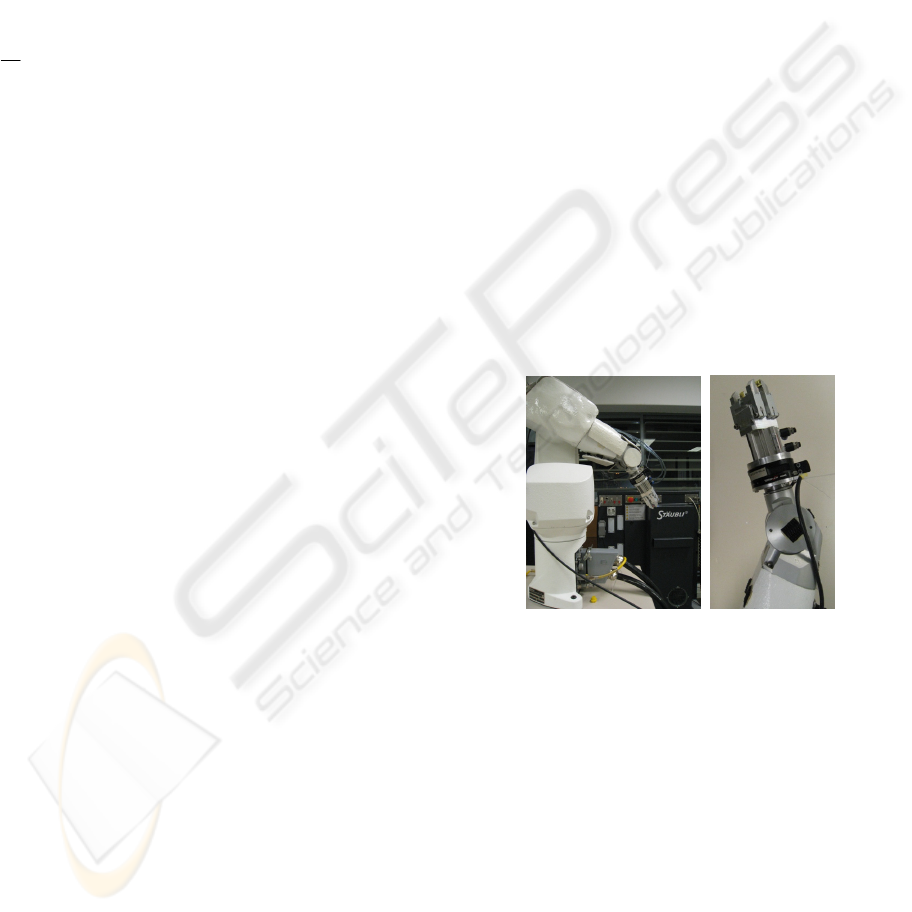
3 EXPERIMENTAL SYSTEM
An experimental setup has been designed in order to
evaluate the different behaviours, shown in Figure 2.
The system developed includes a 6 degrees of
freedom robotic arm manufactured by Stäubli, a
motion controller by Adept, an ATI force and torque
sensor and a Dell personal computer.
Figure 2: Experimental system used for the evaluation of
the proposed behaviour.
The robotic arm is initially programmed to
perform task. The trajectory is specified by either
position and orientation, transformation matrices or
two trajectory paths as mentioned before.
Geometric, cinematic and dynamic restrictions of the
robotic arm are also considered when the trajectory
is programmed.
The motion controller is programmed with a low
level firmware that computes motion commands. A
hybrid position/force control loop is running with a
16 millisecond period time. Motion orders can be
sent in either Cartesian or Joint type, as well as in
either incremental or absolute modes. The motion
FLEXIBLE TRAJECTORY GENERATION TO EXTEND HUMAN-ROBOT INTERACTION WITH DYNAMIC
ENVIRONMENT ADAPTATION
213

controller runs a communication server under
TCP/IP protocol.
The force sensor measures forces and torques
applied at the tool sustained by the robot. An analog
to digital converter hardware and a calibration
routine are called by the personal computer. As a
result, two vectors are ready to be introduced to the
behaviour model: external forces and torques.
The personal computer runs the hybrid
force/position control loop linked to the motion
controller and the force/torque sensor. As described
in next section, a set of algorithms have been
developed to accomplish all computing
requirements.
The control loop accomplishes the main
functionality of the software developed for the
system. The sequence of routines called at each
cycle is:
• Capture position and orientation of the robot
• Capture voltages at the force sensor
• Compute forces and torques from voltages
• Subtract weight of the tool using its orientation
• Calculate new state according to the behaviour
• Send new state to the motion controller
4B4B4 RESULTS AND CONCLUSIONS
The model proposed, based on a double virtual mass
body, and elastic and viscous links has been tested
with some results shown in Figure 3. Different
experiments have been designed and tested. Simple
tasks like object pick and place, path following or
surface polishing are accomplished. During the
execution of the overall task, a perturbation is
introduced by means of external forces and torques.
The system reacts to the perturbations measured by
the force sensor, computing new positions according
to the described model, and sending the perturbed
positions to the motion controller. After the real
perturbation, the virtual forces described earlier act
as guidance of the endpoint, smoothly driving the
end effector back to the pre-programmed path.
In order to increase human capabilities, some
cooperative tasks include virtual constraints. The
proposed model integrates three categories of
restrictions: geometric, kinematic and dynamic. In
order to accomplish the geometric constraints, a
proximity library (Giralt and Hernansanz 2006) and
a surface navigation method (Hernansanz et al 2007)
have been developed and incorporated.
As it’s a parametric model, different responses
can be achieved with the same model. By changing
the values of the virtual mass, elasticity and
viscosity, the behaviour can be tuned according to
specifications of a certain task.
Figure 3: Experimental results. The left picture shows the
perturbation of a trajectory by means of external forces.
The two below the picture describe numerical values of
the reaction. First graph is the evolution of the external
force applied to the endpoint of the manipulator. The
graph in the middle shows the evolution of velocity of the
end effector. Last graph describes position response to
these force steps.
REFERENCES
Dario, P., Carrozza, M.C., Pietrabissa, A., 1999.
Development and in vitro testing of a miniature
robotic system for computer-assisted colonoscopy. In
Computer Aided Surgery; 4(1):1-14.
Zhou, H.X., Guo, Y.H., Yu, X.F., Bao, S.Y., Liu, J.L.,
Zhang, Y., Ren, Y.G., Zheng, Q., 2006. Clinical
characteristics of remote Zeus robot-assisted
laparoscopic cholecystectomy: A report of 40 cases. In
World J Gastroenterol, 12(16):2606-2609.
Kanade, T., 2004. Workshop on Medical Robotics.
International Advanced Robotics Program. Hidden
Valley, Pennsylvania, USA., pp. 19-22.
Rosenberg, L. B., 1993. Virtual fixtures: Perceptual tools
for telerobotic manipulation. In Proceedings of the
IEEE Annual Int. Symposium on Virtual Reality, pp.
76–82.
Bettini, A., Lang, S., Okamura, A., Hager, G., 2002.
Vision Assisted Control for Manipulation Using
Virtual Fixtures: Experiments at Macro and Micro
Scales. In Proceedings International Conference on
Robotics and Automation, pp. 3354-3361.
Giralt X., Hernansanz A., 2006. Optimització de consultes
de proximitat en entorns robotics. In Proceedings 2ª
Jornadas de Recerca en Automàtica, Visió i Robòtica
ESAII IOC IRI, pp. 257-261.
Hernansanz A., Giralt X., Rodriguez A., Amat J., 2007.
RPQ: Robotic Proximity Queries. Developement and
Applications. In Proceedings of The 4th International
Conference on Informatics in Control, Automation and
Robotics. INSTICC Press.
ICINCO 2008 - International Conference on Informatics in Control, Automation and Robotics
214
