INSTRUMENTING BOMB DISPOSAL SUITS WITH WIRELESS
S
ENSOR NETWORKS
John Kemp, Elena I. Gaura and James Brusey
Cogent Computing Applied Research Centre, Coventry University, Priory St, Coventry, CV1 5FB, U.K.
Keywords:
Body sensor networks, first responders, actuation.
Abstract:
Bomb disposal suits contain a large amount of padding and armour to protect the wearer’s vital organs in the
case of explosion. The combination of the heavy (roughly 40kg) suit, physical exertion, and the environment
in which these suits are worn can cause the wearer’s temperature to rise to uncomfortable and potentially
dangerous levels during missions. This paper reports on the development of a wearable wireless sensing
system suitable for deployment in such manned bomb disposal missions. In its final form, the system will
be capable of making in-network autonomous decisions related to the actuation of cooling within the suit, in
order to increase the comfort of the wearer. In addition, it will allow an external observer to remotely monitor
the health and comfort of the operative. Laboratory experiments with the instrumented suit show how skin
temperature varies differently for different skin sites, motivating the need for multiple, distributed sensing.
The need for timely application of in-suit cooling is also shown, as well as the importance of monitoring the
overall health of the wearer of the suit.
1 INTRODUCTION
The monitoring of hazardous environments, along
with the people working within them, is an area which
lends itself to the use of wireless and body sensor
networks (WSNs and BSNs). The field is rich with
potential WSN applications in detecting hazards, pro-
viding feedback to remote observers and other critical
tasks that can increase the safety and benefit the over-
all working conditions of people operating in these
environments. This paper reports the work towards
the development of a wireless body sensor network
for the protective suits worn in bomb disposal mis-
sions.
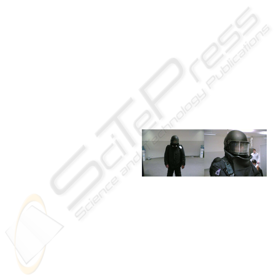
A typical bomb disposal mission will initially in-
volve investigating the site using a remote controlled
robot, and if possible, disarming the bomb remotely.
Sometimes, however, it is necessary for a human
bomb disposal expert to disarm the device. For this,
the expert will put on a protective suit and helmet (as
shown in figure 1), pick up a tool box of equipment,
and walk the 100 or so metres to the site. To reach the
bomb’s location, it may be necessary to climb stairs,
crawl through passageways, or even lie down.
The environment where the suit is used, such as
the hot climate of the Middle East, plays an impor-
Figure 1: Explosive Ordinance Disposal (EOD)Suit.
t
ant role in the design of the protective suit. One of
the UK manufacturers of such suits has identified the
problem of the suit wearer becoming uncomfortably
hot and, in the worst case, suffering heat exhaustion.
They have attempted to address this by installing an
in-suit cooling system based on a dry-ice pack and a
fan that cycles air through the pack and blows cooled
air onto the wearer’s back and into the helmet. The
cooling system has a variable control thus both allow-
ing the airflow to be adjusted for comfort and also
allowing the life of the batteries that power the fan
to be extended, as they would only provide sufficient
power for part of the mission otherwise. The problem
with this cooling approach, though, is that the bomb
disposal expert has other critical concerns during the
mission and either does not bother to put the fan on or
tends to set it to maximum airflow from the beginning
23
Kemp J., I. Gaura E. and Brusey J. (2008).
INSTRUMENTING BOMB DISPOSAL SUITS WITH WIRELESS SENSOR NETWORKS.
In Proceedings of the Fifth International Conference on Informatics in Control, Automation and Robotics - SPSMC, pages 23-31
DOI: 10.5220/0001486400230031
Copyright
c
SciTePress

of the mission.
To address the above problems, this work pro-
poses embedding into the suit a body sensor network
that aims to:
• sense the temperature of the skin of various parts
of the body, in order to assess overall comfort, and
• adjust the cooling dynamically to both remove the
need for human intervention, and also to prolong
battery life.
The prolonging of battery life is intended to provide
cooling over the whole mission duration (compared
to the partial coverage provided currently) rather than
increasing the mission duration itself.
A secondary goal of this work is to help the
manufacturer better understand how the suit material
and design choices are affecting the wearer’s thermal
comfort during use. Finally, the prototype presented
here has been designed such as to allow easy integra-
tion of additional sensors, such as accelerometers to
monitor posture, heart rate monitors, and CO
2
sens-
ing within the helmet.
The paper is organised as follows: Section 2 ex-
amines related work, focusing in particular on body
sensor networks and research relating to instrument-
ing first responders (such as police, fire services etc).
Section 3 describes the system design and architec-
ture developed for the prototype system produced to
date. Section 4 contains an evaluation of the proto-
type. Finally the paper concludes with some obser-
vations based on the work so far and outlines future
work.
2 RELATED WORK
The work reported in this paper is most closely
aligned with respect to the instrumentation design and
implementation with the field of Body Sensor Net-
works. This is a sub-area of Wireless Sensor Net-
works that makes use of a combination of wireless
and miniaturised sensor technologies to monitor the
human body. The scope of present BSN approaches
is patient care. Such systems are either designed to fo-
cus on capturing the evolution of a particular physio-
logical parameter and ensuring that alarms are gener-
ated when parameters stray outside a safe range (Keoh
et al., 2007), or aimed to provide general monitoring
solutions for patient status within a hospital or similar
environment (Shnayder et al., 2005). In comparison,
the work presented here is concerned with increased
safety and comfort of human subjects in constrained
environments through integrating sensing, actuation,
and autonomous decision making. In this context,
wireless sensor technology is used as an enabler for
the necessary detailed measurement of physiological
parameters. 5A This work shares some of the design
space of BSN in terms of the type of physiological
parameters sensed and the wearability requirements
of the implemented system. On the other hand, given
that the application is within the safety critical do-
main, the work here also shares some common char-
acteristics with the area of instrumenting and monitor-
ing first responders. In this section, samples of BSN
platforms are reviewed together with commercial in-
stances of first responder monitoring and prior, moti-
vating, physiological findings about the EOD suit.
2.1 Body Sensor Networks—Platforms
BSN based systems are often more constrained than
ordinary embedded systems. These constraints are
mainly in terms of power, size and weight. Power
is restricted because mains AC power is not avail-
able. Furthermore, size and weight restrictions limit
the battery supplies that can be used. Size and weight
must be limited because large and heavy devices
would be cumbersome, uncomfortable, and in appli-
cations such as the one described here, an unnecessary
distraction.
In response to the above, some of the BSN sys-
tems designed and implemented by research groups
integrate within the nodes an appropriate central pro-
cessing unit, memory and radio transceiver as a single
custom chip. An example here is the MITes platform
(for monitoring movement of human subjects) devel-
oped by (Tapia et al., 2004), which is based around the
Nordic VLSI Semiconductors nRF24E1 chip. This
chip integrates a radio transceiver and an Intel 8051
based processor core that runs at 16MHz and pro-
vides a nine channel 12-bit ADC and various other in-
terfaces, such as SPI (serial peripheral interface) and
GPIO (general purpose I/O). This approach is effi-
cient in terms of size and weight due to the integra-
tion of several functions into one chip, but has limited
generality as it can not be easily adapted for new ap-
plications.
Another, more popular design option is to use off-
the-shelf components. There is a trade off made be-
tween processing and storage capabilities and the size
and power consumption of the devices. This means
that the devices selected would likely be considered
severely under-powered in other systems (often in-
cluding 16- or even 8-bit processors) and have small
amounts of memory (in the order of tens or hundreds
of kilobytes). For instance, the Texas Instruments
MSP430F149 micro-controller has been used for sev-
eral systems including those developed by (Lo and
ICINCO 2008 - International Conference on Informatics in Control, Automation and Robotics
24

Yang, 2005) and (Jovanov et al., 2001). This is a 16-
bit processor running at 8MHz incorporating 60KB
of flash memory and 2KB of RAM and provides in-
terfacing opportunities via 48 GPIO lines and a 12-bit
ADC. The system developed by Lo and Yang used
ECG sensors, accelerometers, and a temperature sen-
sor to monitor patient health. The system developed
by Jovanov et al., was used for monitoring the elderly
and those undergoing physiotherapy.
Other systems expand upon commercial devices
such as the Mica2 and MicaZ motes developed at the
University of California, Berkeley, or Intel’s Imote
platform. This approach often has a disadvantage in
that the basic platform is generic, and may not di-
rectly provide the facilities required for the specific
BSN project. Such commercial platforms are also
often larger and heavier than custom developed plat-
forms as they are required to be general purpose in
order to achieve any commercial success. The MicaZ
mote uses the Atmega128L, an 8-bit processor run-
ning at 8MHz and featuring 128KB of flash memory
to which an additional 512KB is added externally on
the mote itself. A 10-bit ADC, UART and I2C bus are
also available. (Gao et al., 2005) developed a system
based around the this mote, adding various sensors
and supporting devices to allow patient tagging and
monitoring in an emergency response environment.
(Walker et al., 2006) present a blood pressure mon-
itoring system based on the MicaZ platform. In that
work, a commercial blood pressure monitoring device
is connected to the MicaZ via a serial interface.
2.2 Instrumenting First Responders
The best fit example of a commercial product de-
signed for the purpose of monitoring personnel carry-
ing out missions in dangerous environments is the Vi-
voResponder by (Vivometrics, 2007). VivoResponder
is based upon an earlier product called the LifeShirt
and is aimed at personnel engaged in firefighting
and hazardous materials training or emergency re-
sponse, industrial clean-ups using protective gear, and
biohazard-related occupational work. The VivoRe-
sponder is supplied in three parts: a lightweight, ma-
chine washable chest strap with embedded sensors; a
data receiver; and, VivoCommand software for moni-
toring and data analysis. The sensors embedded in the
chest strap monitor the subject’s breathing rate, heart
rate, activity level, posture, and single point skin tem-
perature.
Monitoring of the subject’s breathing is performed
using a method called inductive plethysmography,
where breathing patterns are monitored by passing a
low voltage electrical current through a series of con-
tact points around the subject’s ribcage and abdomen.
Monitoring of the subject’s heart rate is performed via
an ECG.
The VivoCommand software, provided with the
device, displays the gathered data from the chest strap
in real-time on a remote PC. The parameters are up-
dated every second along with 30-second average
trends. The parameters are displayed with colour cod-
ing intended to allow quick assessment of the status of
up to 25 monitored personnel simultaneously. Base-
line readings can be set individually per monitored
person.
The work developed here differs in intent: the aim
here is to provide a detailed thermal assessment based
on sensors integrated into the protective suit and de-
liver remotely abstracted comfort information.
2.3 Other Work on EOD Suits
Working from a physiological perspective, (Thake
and Price, 2007) have investigated the thermal strain
of a subject when wearing EOD suits in hot envi-
ronments. The work looks at quantifying the level
of strain by assessing how hot and tired the suit
wearer feels whilst wearing various combinations of
suit components. An “activity” regime was developed
for the assessment based on the types of activities that
a bomb disposal technician would undergo during a
mission and included walking on a treadmill, unload-
ing and loading weights from a rucksack, crawling
and searching activity, arm cranking and cognitive
tests. Aspects of hand-eye coordination and psycho-
logical performance were also assessed. The inves-
tigations have demonstrated a large increase in phys-
iological strain when wearing the EOD suit, though
benefits have been shown when the ambient air is
cooled for the suit ventilation purpose and lighter-
weight trousers are worn.
It is indeed these types of studies, together with
the user requests, that prompted the development
of the detailed physiological monitoring system pre-
sented in this paper. The activity regimes described
by Thake and Price were used in the experiments pre-
sented in this paper to allow validation of findings.
3 SYSTEM DESIGN AND
ARCHITECTURE
The main part of the prototype system is designed
following a sense-model-decide-act architecture as
shown in figure 2. The environment within the suit
is sensed in terms of temperature; sensed data is in-
tegrated into a model representing the thermal state
INSTRUMENTING BOMB DISPOSAL SUITS WITH WIRELESS SENSOR NETWORKS
25
environment
sense
model
decide
act
transmit
visualise
mission plan
changes
Figure 2: Conceptual design of prototype system.
of the wearer; a decision is made about how to ad-
just the cooling system based on the thermal state; fi-
nally, the determined action is transmitted to the fan
speed controller. In addition to this basic architec-
ture, the system also transmits inferred state values
for the purpose of remote, on-line, visualisation of
the thermal state of the wearer. From this visualisa-
tion, the operator can assess how different parts of
the mission, or different actions being taken by the
suit wearer are affecting their thermal state and hence
assess the wearer’s fitness for the mission. (It is ex-
pected that such information, collected during field
trials and real missions, might lead to changes to fu-
ture mission planning or to changes in the design of
the suit.) In summary, the prototype system can be
seen as being composed of two control loops: one
giving rapid feedback to autonomously adjust cool-
ing; the other, longer term one, providing support for
an iterative design process in terms of both the mis-
sion use and construction of the suit.
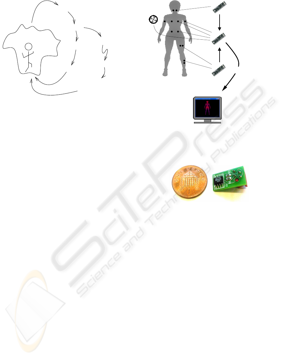
The prototype design consists of a number of
hardware components, including a remote monitor-
ing station, two processing nodes, one actuation node,
12 temperature sensors, and the cooling system. The
connection between these components is shown in
figure 3. The processing nodes, actuation nodes, and
remote monitoring point form a wireless network.
Each processing node is wired to several sensor pack-
ages via an I2C bus. Although it would be possible
to integrate all sensor packages used in this proto-
type into a single processing / actuation node, using
separate processing nodes allows the helmet, jacket,
and trousers to be kept separate with no wires run-
ning between them. This is essential for ensuring that
the product remains easy to use and transparent to the
wearer.
The system componentsand their functionality are
described in the remainder of this section.
System
Cooling
Remote Monitoring Point
Subject with Sensors
Processing Node
Actuation Node
E
F
D
A
C
B
Processing Node
Figure 3: Prototype system hardware components and sen-
sor positioning (A – neck, B – chest, C – bicep, D – ab-
domen, E – thigh, F – calf).
Figure 4: Sensor package, which is based on an ADT75A
chip.
3.1 Sensor Packages and Sensor
Positioning
The prototype system discussed here uses twelve sen-
sor packages based on Analog Devices ADT75A tem-
perature sensor ICs (shown in figure 4). This device
has the advantage that it contains the sensor, ADC,
and bus interface in a single package. Temperature
values are transmitted as 12 bits, which causes round-
ing to within 1/8°C. The sensor packages are con-
nected to only two nodes in the current version: one
actuation node and one processing node.
The sensor packages were positioned around var-
ious parts of the body roughly following the standard
positioning used for skin sensors as used by (Thake
and Price, 2007), which is a subset of the locations
discussed by (Shanks, 1975). These were: lateral
calf muscle, front of thigh (or quadruceps), abdomen,
chest, biceps, and neck, as indicated in figure 3. Given
that temperatures are known to be symmetrical be-
tween left and right sides in healthy people (Silber-
stein et al., 1975), sensors have been placed on a sin-
gle side. Two sensor packages were used per skin site.
ICINCO 2008 - International Conference on Informatics in Control, Automation and Robotics
26
This arrangement enables individual data validation.
3.2 Processing and Actuation Nodes
3.2.1 Construction
There are a variety of available embedded platforms
for sensing and control applications. The hardware
choice decisions for the prototype system here were
based on the available platforms’ processing power,
external interfaces, ease of software development,and
size.
Gumstix Connex 400xm-bt boards were selected
as the main processing platform. Although not as
popular as Mica2 motes, they are becoming more
prevalent (see (Keoh et al., 2007) for an example).
These devices offer more processing power and mem-
ory (in terms of both RAM and flash) than many sim-
ilarly sized platforms. The Connex includes an Intel
XScale PXA255 400MHz processor, 16MB of flash
memory, 64MB of RAM, a Bluetooth controller and
antenna, and 60-pin and 92-pin connectors for expan-
sion boards. There are no on-board sensors provided.
The sensor packages connect to the Connex board via
an expansion board, designed in-house.
The prototype system exploits the following ca-
pabilities offered by the Gumstix Connex device:
Bluetooth communications to transmit data between
nodes; I2C bus interface for the attachment of sen-
sor packages; real-time data modelling and decision-
making; and, a small form factor, which enables con-
venient mounting on or around a subject’s body.
3.2.2 Functionality
In the current revision of the prototype, the actua-
tion and processing nodes only transmit data back to
the remote monitoring station, upon filtering outlying
values. The longer term view is for the processing
and actuation nodes to perform in-network modelling
of the suit wearer’s comfort through collaborative be-
haviour. Comfort modellingwould firstly involve pro-
duction of a thermal sensation model within the net-
work. This will be followed by integration of sup-
plementary physiological and contextual sensing per-
formed by expanded sensor packages. Work to date in
thermal sensation modelling and its integration within
the processing and actuation nodes is reported in a
separate paper. The actuation node will eventually be
used to perform decision making on the basis of the
wearer’s comfort and act by controlling the fan speed.
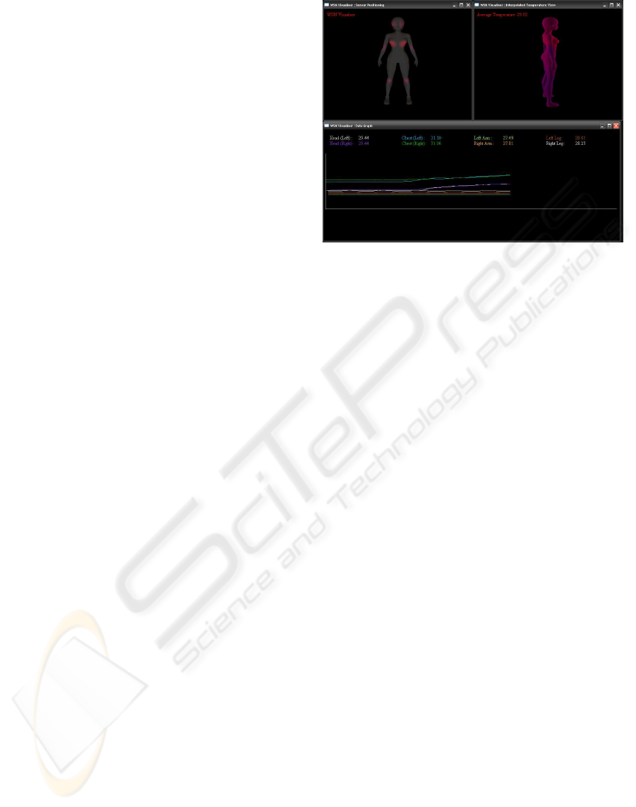
Figure 5: A snapshot of the remote monitoring component.
3.3 Remote Monitoring
The remote monitoring component of this system al-
lows an external observer to monitor both the instru-
mentation system (to ensure that trustworthy informa-
tion is being recorded) and the bomb disposal techni-
cian during a mission (which is the main function of
the instrumentation). The remote monitoring compo-
nent displays the health and comfort information and
provides alerts to the remote observer if physiologi-
cal parameters fall outside safe ranges or the wearer
is shown to be significantly uncomfortable. A snap-
shot of the remote monitoring component is shown in
figure 5. Currently the remote monitor displays skin
site temperature data and a rotating, suggestive, 3-D
interpolated model of skin temperatures. Cool to hot
zones are displayed dynamically through a range of
colours, from blue to red.
4 PROTOTYPE EVALUATION
4.1 Experimental Setup
The prototype instrumentation system was evaluated
through laboratory experiments that attempt to repro-
duce typical bomb disposal mission situations by hav-
ing the subject undertake a series of activities and
tasks, as discussed in section 2.3. The experiments
begin with sensors being attached to the subject, fol-
lowed by suiting-up. The upper body sensors are in-
tegrated into the clothing and thus easier to attach,
whilst lower body sensors are attached with PVC
tape. The subject wore the outer shell of the bomb dis-
posal suit including the jacket and trouser segments in
addition to armour plating and the helmet.
INSTRUMENTING BOMB DISPOSAL SUITS WITH WIRELESS SENSOR NETWORKS
27
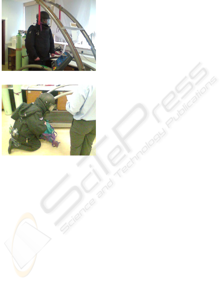
Figure 6: First activity: walking at 4km/h.
Figure 7: Second activity: kneeling while removing weights
from a sack. The wired-in data logger can be seen taped
onto the subject’s lower back.
The subject then undertakes an activity regime
composed of: (1) walking (3 minutes) (see figure 6);
(2) kneeling while putting weights into and out of a
rucksack (2 minutes) (see figure 7); (3) crawling (2
minutes); (4) arm exercise (4 minutes); (5) sitting (3
minutes); (6) standing (1 minute). Temperature data
is collected both via the prototype wireless system
and via a wired-in data logger. Data was gathered dur-
ing two consecutive runs, both consisting of the same
routine and taking place in a 5m x 6m draft free room,
with an ambient temperature of 21°C.
4.2 Evaluation Results
The prototypewas evaluated according to a number of
criteria that follow directly from user requirements.
The criteria were: ease of use, data yield, accuracy,
robustness, communication range, and information
gain.
Ease of Use. Instrumentation systems, particu-
larly those used for bomb disposal missions, are ex-
pected to have stringent ease of use requirements as
they should be transparent to the user and should not
interfere with the mission. Ease of use was assessed
here subjectively by comparing the ease of applica-
tion of the sensor packages with sensor mountings for
a wired data logger.
As mentioned previously some of the sensor pack-
ages have been integrated into clothing, whilst some
(neck, thigh, and calf) have been taped to the skin.
It is expected that clothing integrated sensors will be
less accurate than ones taped to the skin because con-
tact with the skin surface will change when the sub-
ject is moving. While avoiding the problem of incon-
sistent contact, taping on sensors, on the other hand,
means that they are less convenient to apply and re-
move. In comparison to using a standard wired data
logger, the wireless system mounting takes consider-
ably less time and has been found to be more comfort-
able by experimental subjects. Further revisions of
the prototype will have all sensor packages mounted
on individual elasticated straps, ensuring both firm
contact and comfort.
Data Yield is a measure of the proportion of data
captured. Wireless sensing systems are inherently
prone to low yields due to both transmission errors
and sensor faults. For the system here, during experi-
mentation, no packets were lost in transmission, how-
ever 5% of the sensor samples were found to be out
of range (95% yield). Most of the out of range val-
ues were from particular sensor packages (3.3% from
the worst two), with several sensor packages having
no out of range values at all. It is likely that the er-
roneous values were introduced by I2C bus transmis-
sion errors. In comparison, there were no errors ap-
parent in the wired data logger values apart from the
chest sensor, which produced incorrect values 61% of
the time (39% yield for this sensor, 88% over all data
logger sensors).
Accuracy is a measure of how closely the sensor
data obtained corresponds to the underlying physical
phenomena being sensed. As the data logger results
in figure 9 show, calibration is needed. Discretisation
due to the 12 bit resolution causes some information
loss that is offset by sampling frequently. The sys-
tem is currently being calibrated against a newer data
logger instrument.
Robustness is particularly important for this sys-
tem as the intended usage scenario involves it func-
tioning in an environment where it may be subjected
to large mechanical shocks and radio frequency in-
terference (RFI). The activity regime here reproduces
shocks roughly equivalent to normal application us-
age and the prototype functioned correctly throughout
all trials. As yet, no RFI testing has been carried out.
Communication Range is a measure of how far
the subject can roam from the monitoring station
ICINCO 2008 - International Conference on Informatics in Control, Automation and Robotics
28

without losing communications. In line-of-sight tests,
a range of 50 metres was achieved,whilst non-line-of-
sight range (through several walls) was about 10 me-
tres. Bluetooth communication will be replaced by
ZigBee in the next revision of the prototype.
Information Gain is a measure of the benefit
of the system in terms of providing more (or bet-
ter) information about the subject. The prototype
has demonstrated two advantages. First, by being
untethered, it allows data gathering to occur in the
field. Second, it provides a means for real-time re-
mote monitoring and actuation as opposed to offline
data acquisition, which is the only role fulfilled by the
wired data logger.
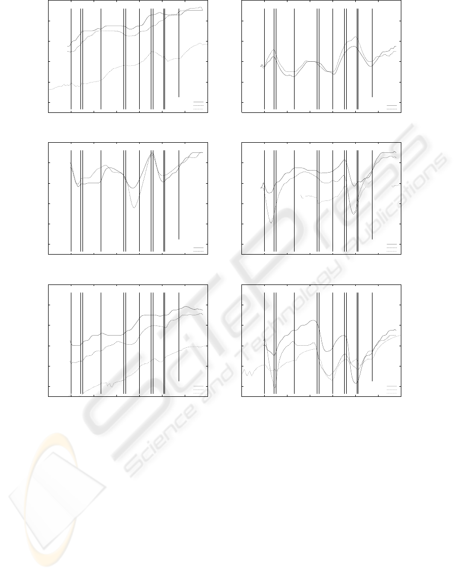
4.3 Data Analysis
A summary of temperature data obtained from all sen-
sors for a sample run is given in the series of graphs
in figure 9. Data was recorded during the experimen-
tation using both the prototype system and a wired-in
data logger. These graphs show that the two systems
agree in terms of the changes in temperature. It is
important to note that the shapes of the graphs, not
the exact temperatures measured, are compared here
as the sensors on the prototype system had not yet
been fully calibrated. The graphs show sensed tem-
peratures over a period of time starting from the third
activity (crawling) through to the fifth activity (sit-
ting) followed by a repeat from the first (walking on a
treadmill) through to the last again (see section 4.1).
In the graphs, the start and end times for each activity
are indicated by a vertical bar and the activity num-
ber (starting with 3) is given in between each set of
bars. Note that there were some rest periods between
activities, which are left unmarked.
The aim of the experimentation carried out was
two-fold. First, the system under development was
compared, in terms of the criteria discussed previ-
ously, with a commercially available, wired-in data
logger. Second, the data obtained from the two sys-
tems was compared to check for consistency. The po-
sitioning of the sensors, with several locations having
more than one sensor, also meant that the data from
the system could be compared internally.
While detailed interpretation of the physiological
meaning of the data obtained is beyond the scope of
this paper, the data gathered is meaningful in the con-
text of the developed application as follows: 1) Large
variations in the skin temperature on some of the sites
monitored (maximum three degrees C over 30 min-
utes) indicate the need for both monitoring and ac-
curate cooling actuation; 2) There are uncorrelated
skin temperature variations over the sites monitored
Figure 8: Enhanced sensor package, which is comprised
of a PIC processor, 3-DOF accelerometer, I2C buffer, and
temperature sensor.
stressing the need for distributed and detailed mea-
surement (as opposed to single point measurement
performed by most developed BSN systems); 3) From
the graphs, the relationship between activity and skin
temperature at different sites is not an obvious one.
(An example here is the sudden dip in temperature
which occurs for all chest sensors during crawling
(activity 3). Crawling is strenuous with the suit on,
so this result is surprising.) This indicates the need
for added sensing such as humidity and posture infor-
mation in order to predict the physiological effects of
wearing the suit during such exercise regimes. The
next prototype, currently under production contains
such enhanced sensor packages.
5 CONCLUSIONS AND FUTURE
WORK
WSN technology is clearly an enabler for detailed
measurement in domains such as the one discussed
in this paper, domains which are currently not suffi-
ciently understood and lack the necessary instrumen-
tation to further scientific investigation.
Experimental results obtained with a detailed,
WSN-based temperature monitoring instrument
showed that 1) under a set of activities typical to
a bomb disposal mission, skin temperatures for
different parts of the body (arms, thigh, chest, and so
forth) vary differently thus there is value in sampling
at many points; 2) skin temperatures exhibit large
variations leading potentially to heat exhaustion
hence the need for health monitoring of subjects; 3)
autonomous feedback control of the in-suit cooling
system, based on a detailed map of how temperature
is changing over time, is enabled by the prototype
developed so far but more work is needed to deter-
mine how best to respond to changes in temperature
to ensure that the wearer is kept comfortable.
In the next revision of the prototype, it is planned
INSTRUMENTING BOMB DISPOSAL SUITS WITH WIRELESS SENSOR NETWORKS
29
33
34
35
36
37
38
0 5 10 15 20 25 30 35
Temperature (degrees Celsius)
Time (minutes)
3 4 5 1 2 3 4 5
Right Arm
Left Arm
Logger
33
34
35
36
37
38
0 5 10 15 20 25 30 35
Temperature (degrees Celsius)
Time (minutes)
3 4 5 1 2 3 4 53 4 5 1 2 3 4 5
Right Neck
Left Neck
(a) (b)
33
34
35
36
37
38
0 5 10 15 20 25 30 35
Temperature (degrees Celsius)
Time (minutes)
3 4 5 1 2 3 4 53 4 5 1 2 3 4 53 4 5 1 2 3 4 53 4 5 1 2 3 4 5
Right Abdomen
Left Abdomen
33
34
35
36
37
38
0 5 10 15 20 25 30 35
Temperature (degrees Celsius)
Time (minutes)
3 4 5 1 2 3 4 53 4 5 1 2 3 4 53 4 5 1 2 3 4 5
Right Chest
Left Chest
Logger
(c) (d)
33
34
35
36
37
38
0 5 10 15 20 25 30 35
Temperature (degrees Celsius)
Time (minutes)
3 4 5 1 2 3 4 53 4 5 1 2 3 4 53 4 5 1 2 3 4 53 4 5 1 2 3 4 53 4 5 1 2 3 4 5
Right Thigh (1)
Right Thigh (2)
Logger
33
34
35
36
37
38
0 5 10 15 20 25 30 35
Temperature (degrees Celsius)
Time (minutes)
3 4 5 1 2 3 4 53 4 5 1 2 3 4 53 4 5 1 2 3 4 53 4 5 1 2 3 4 53 4 5 1 2 3 4 53 4 5 1 2 3 4 5
Right Calf (1)
Right Calf (2)
Logger
(e) (f)
Figure 9: Skin temperature over time for (a) arm, (b) neck, (c) abdomen, (d) chest, (e) thigh, and (f) calf sites. The two
leg sensors (thigh and calf positions) were placed on the right leg only. For several skin sites, temperature values were also
obtained using a wired-in data logger (denoted “Logger”). The vertical lines in each graph show the start and end of activities.
Each activity is represented by a number.
to integrate temperature sensors into a multi-modal
sensor board designed in-house, as shown in fig-
ure 8. Each board has a temperature sensor and an ac-
celerometer, along with a PIC micro-controller. The
two sensors allow the combined monitoring of tem-
perature and acceleration data at any point on a sub-
ject’s body. The acceleration data will be used for
posture identification in further work, which will al-
low enhanced, activity based remote visualisation of
the subject and lead to improved estimates about how
the thermal state and thus comfort of the subject is
changing. This will hence improve the timeliness and
appropriateness of autonomous cooling decisions.
ACKNOWLEDGEMENTS
The authors wish to thank Doug Thake and his stu-
dents for the use of and assistance with the Coventry
University Health and Life Sciences laboratory and
equipment. The authors also wish to thank Bob New-
man for his contribution to hardware development in
the early stages of this project.
ICINCO 2008 - International Conference on Informatics in Control, Automation and Robotics
30

REFERENCES
Gao, T., Greenspan, D., Welsh, M., Juang, R. R., and Alm,
A. (2005). Vital signs monitoring and patient track-
ing over a wireless network. In 27th Annual Interna-
tional Conference of the IEEE EMBS, pages 102–105,
Shanghai.
Jovanov, E., Raskovic, D., Price, J., Chapman, J., Moore,
A., and Krishnamurthy, A. (2001). Patient monitor-
ing using personal area networks of wireless intelli-
gent sensors. Biomedical Sciences Instrumentation,
37:373–378.
Keoh, S. L., Dulay, N., Lupu, E., Twidle, K., Schaeffer-
Filho, A. E., Sloman, M., Heeps, S., Strowes, S., and
Sventek, J. (2007). Self managed cell: A middle-
ware for managing body sensor networks. In Pro-
ceedings of the 4th International Conference on Mo-
bile and Ubiquitous Systems: Computing, Networking
and Services (Mobiquitous), Philadelphia, USA.
Lo, B. and Yang, G.-Z. (2005). Architecture for body sen-
sor networks. In Perspective in Pervasive Computing,
pages 23–28.
Shanks, C. A. (1975). Mean skin temperature during anaes-
thesia: An assessment of formulae in the supine surgi-
cal patient. British Journal of Anaesthesia, 47(8):871–
876.
Shnayder, V., rong Chen, B., Lorincz, K., Fulford-Jones,
T. R. F., and Welsh, M. (2005). Sensor networks for
medical care. Technical report, Division of Engineer-
ing and Applied Sciences, Harvard University.
Silberstein, E., Bahra, G., and Kattan, J. (1975). Thermo-
graphically measured normal skin temperature asym-
metry in the human male. Cancer, 36(4):1506–1510.
Tapia, E. M., Marmasse, N., Intille, S. S., and Larson, K.
(2004). Mites: Wireless portable sensors for study-
ing behavior. In Proceedings of Extended Abstracts
UbiComp 2004: Ubiquitous Computing.
Thake, C. D. and Price, M. J. (2007). Reducing uncom-
pensable heat stress an a bomb disposal (EOD) suit:
a laboratory based assessment. In Proceedings of the
12th International Conference on Environmental Er-
gonomics (ICEE 2007), Piran, Slovenia. ISBN 978-
961-90545-1-2.
Vivometrics (2007). Vivometrics: Better results
through non-invasive monitoring. Website.
http://www.vivometrics.com; (Online; accessed
16/11/2007).
Walker, W., Polk, T., Hande, A., and Bhatia, D. (2006). Re-
mote blood pressure monitoring using a wireless sen-
sor network. In 6th Annual IEEE Emerging Informa-
tion Technology Conference, Dallas, Texas.
INSTRUMENTING BOMB DISPOSAL SUITS WITH WIRELESS SENSOR NETWORKS
31
