HYDROGEN POWERED CAR CONTROL SYSTEM
Srovnal Vilem, Koziorek Jiri, Horak Bohumil
Department of Measurement and Control, FEECS,VSB
Technical University of Ostrava, 17. listopadu 15, 708 3, Ostrava-Poruba, Czech Republic
Adam George, Garani Georgia
Technological Educational Institute of Larissa, Greece
Keywords: Vehicle Control System, Distributed Control System, Multi-agents, Learning, Optimizing.
Abstract: The main goal of the research project was designing and realization a distributed control system of the
hydrogen powered prototype car. Next goals of project were real time control, speed and final time
optimizing with minimal fuel consumption and monitoring of driver biomedical parameters. The control
system was realized by several mobile embedded systems and one central system. The embedded systems
hardware was realized with Freescale processors and communication CAN bus. Central system hardware
was realized by notebook and communication with embedded systems in car was realized by GSM
communication. Control system software using of multi-agent technology with dynamic mutual negotiation
of mobile system parts. This task allows in a form of control system for prototype race car modelling of
distributed control system. The real hardware and software model is also important motivation for extended
research.
1 INTRODUCTION
A team of several specialists and students of
Department of Measurement and Control, VSB-
Technical University of Ostrava have designed and
realized a prototype of hydrogen powered car based
on fuel cell technology and electrical DC drive. The
project is called HydrogenIX and the works and
testing activities came through between October
2004 and today.
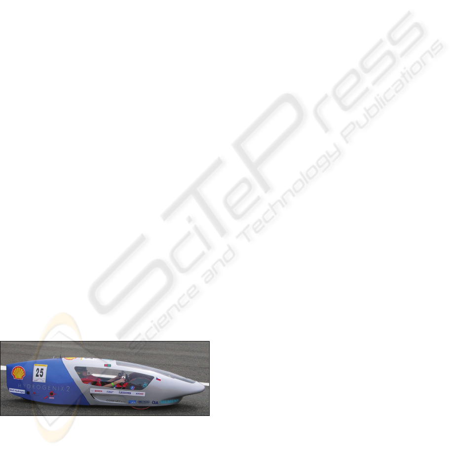
Figure 1: The HydrogenIX car.
The motivations for the project are following:
• There is The Laboratory of Fuel Cells at
Department of Measurement and Control. The
development of mentioned car is first
application of fuel cell in mobile system at the
laboratory.
• Activation of the interest of students, Ph.D.
students, researchers and public in renewable
and alternative energy sources.
• Involve students to design and development
activities in interesting area and demonstrate the
result of the project in a competition of
economization of energy in mobile vehicles.
The competition is called Shell Eco-Marathon.
The Shell Eco-Marathon is a competition
organized by Shell Company and take place at race
circuit in Nogaro, France. Teams of whole Europe
try to reach highest distance with 1 liter of petrol, in
the other words to have lowest consumption of the
fuel. Even if the majority of teams use petrol engines
in their vehicles, there are also vehicles powered by
diesel, LPG, hydrogen and other alternative
energies. The results are obtained by recalculating
using calorific value of each type of fuel. So that it is
possible to compare different types of fuel.
62
Vilem S., Jiri K., Bohumil H., George A. and Georgia G. (2008).
HYDROGEN POWERED CAR CONTROL SYSTEM.
In Proceedings of the Fifth International Conference on Informatics in Control, Automation and Robotics - RA, pages 62-66
DOI: 10.5220/0001485900620066
Copyright
c
SciTePress
2 CONTROL SYSTEM
The vehicle powered by hydrogen fuel cell needs
electronic a control system assuring operation of its
different parts. The complex electronic control is
necessary already for basic operation of the vehicle,
because there are lots of subsystems that have to be
coordinated and controlled. The control system
assures especially following tasks:
• Control of fuel cell operation – hydrogen input
valve control, combustion products output valve
control, fuel cell fan control, coupling of
produced electrical energy to electric DC-drive
system.
• Control of DC-drive system – motor current
control, speed control.
• Processing security tasks – assuring safe
operation of fuel cell system and drive system,
processing of hydrogen detector information,
temperature measuring.
• Managing the driver control panel – complete
interface to pilot that allows controlling the car
– start/stop, speed set point, time measuring,
emergency buttons and indicators.
• Creating data archives with saved process
variables – saving important process data to
archives that can be then exported and analyzed.
• Sending actual data to display panel in car –
display panel in the car is the “process”
visualization of the system. All important data
are online displayed on it.
• Communication with PC monitoring station –
control system send data and receive commands
from PC monitoring station using wireless
communication system.
The car onboard control system is built on
embedded system with Freescale HC12
microprocessors. The control system has distributed
architecture and it is divided into two parts:
• A fuel-cell control block that controls whole
installation of the fuel-cell, DC drive system
and security tasks.
• An interface control block that assures interface
to the pilot, a wireless communication with PC
monitoring station. This block contains the text
display, which is used to monitor important
parameter of the car and makes possible to do
important settings.
Both part of control system are connected via
CAN communication network. The wireless
communication between the car and with PC
monitoring station is realized by GSM
communication – GPRS data transfer. The data
transfer is realized by dial-up connection.
The PC monitoring station operates a process
visualization application that is realized by SCADA
system Promotic. The process visualization displays
all parameters measured during the car operation, all
the system states and alarms, make possible to
display trends of required values and log measured
data in data archives.
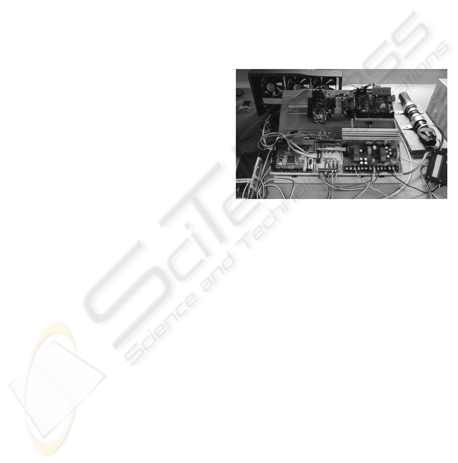
The complete block diagram of the car control
system is demonstrated in figure 3 and realization in
figure 2.
Figure 2: The HydrogenIX car control electronic testing
workplace.
2.1 Operating Values Monitoring
The car control system monitors a lot of variables.
Some of these variables are used for basic control
activities, the others are used for optimization of
operation. The measured variables are following:
• Electrical variables – fuel cell voltage and
current, motor voltage and current, voltages of
super-capacitor and on-board battery.
• Non-electrical variables – temperatures and
pressures in fuel cell circuit, car speed.
• The system is ready for measurement of others
supplementary variables that can be used for
optimization of the operation – wind speed,
outside temperature, track position.
HYDROGEN POWERED CAR CONTROL SYSTEM
63
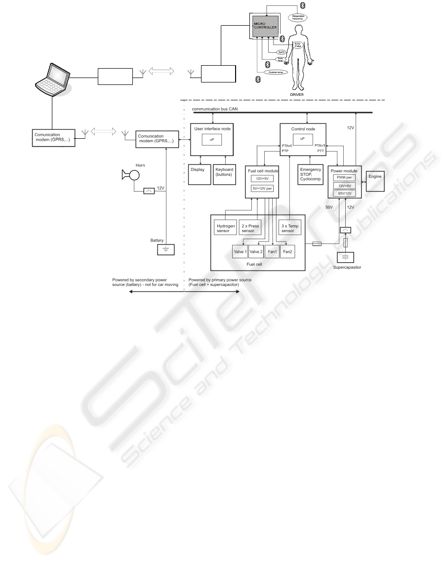
Figure 3: The HydrogenIX car control electronic block scheme.
2.2 Bio-telemetry System
The vehicle is also equipped by bio-telemetry
system that makes possible to monitor biological
functions of the pilot. The embedded portable
telemetry system of biological parameters serves for
reading and wireless data transfer of measured
values of selected biological parameters to far
computer.
The telemetric system can be used for real time
monitoring of the basic life functions of race driver.
The driver has to be very concentrated and the
reactions of driver have to be very quick. The
telemetry system provides better control of physical
and psychical condition of driver during race. It is
possible to analyze effect of a stress situations, high
speed and high psychical stress on the race driver
during the race and crisis situation, more precisely
during high physical and psychical stress.
For biophysical monitoring were chosen these
parameters: Electrocardiography – ECG, Pulse
frequency, Oxygen saturation – SpO2, Body
temperature, Outside temperature and Respiration
frequency.
3 MULTI-AGENT CONCEPT OF
CONTROL SYSTEM
The track passage optimization task of the laboratory
car with minimal energy consumption in real time is
quite complex.
Range of inputs and outputs of the control
system, communication flows and safety of
operation require the adaptability at occurred
situations and environment changes – strategy
control by multi-agent systems (MAS). Among basic
expected properties of proposed MAS belong a
strategic, targeted system behavior, robustness and
adaptability at environment changes.
This can be provided by decentralization of
control activities in the control system, by
distribution of functions and by modularity based on
fundamental elements – agents (Srovnal, V.,
Pavliska, A., 2002).
Comunication
modem
Comunication
modem
ICINCO 2008 - International Conference on Informatics in Control, Automation and Robotics
64

3.1 MAS Structure Description
The higher level of control system is represented by
a personal computer. In the PC the signal from
differentially GPS positioning system may be
entered, which represents the relative coordinate
system of environment – allow the precise of the
position of the race car on the circuit. At the output
is connected GPRS communication modem which
transmits commands for race car.
The algorithm of agent’s cooperation was
proposed with the control agent on a higher level.
The control agent determines the required behavior
of the whole control system as the response to the
dynamic behavior of car and to the one‘s own global
strategy in the task and knowledge about the last
situations, which are saved in the database. The
agent on a higher level controls the other agents
(Srovnal, V., Horák, B. and Bernatik, R., 2004).
The separate task is the transformation which
converts the digital data position into the object
coordinates (car position on the circuit) which are
saved in the database of the circuit. This database is
common for all agents in the control system. Each
agent sees actual the whole data and is capable of
controlling its behavior in a qualified way. The basic
characteristic of a control algorithm of a subordinate
agent is the independence on the number of decision
making agents for car on the circuit.
Agent system has a common goal, to control of
the car during race with optimizing - minimizing of
fuel consumption and control of critical speed. For
successful assertion of one’s own race strategy the
extraction and knowledge of changeable
environment and learning capabilities are very
important.
Main architecture of such hybrid agent system is
characterized via:
• Layered control. Agent is described by number
layers of abstraction and complexity.
• Layered knowledge base.
• Bottom-up activating
• Top-down execution.
Agent is connected with environment through
interface with sensors, actuators and communication
module. Control is allowed through layers at three
levels: reactive layer, layer of local planning, and
layer of cooperative planning. They are use
information from knowledge bases (“world” model,
“mental” model and “social” model), (Garani, G.
and Adam, G., 2006).
Reactive layer is responsible for adequate
reactions at the stimulations from environment that
require immediate reaction and execution of called
procedures from local planning layer. Fundamental
characterization of such layer is:
• Use of effective algorithm of compare with
patterns of behavior. Serve to pick-out of the
actual situations.
• Situation description for timely actual reactions
at received stimulus.
• Hard-wired links. Recognized situations are fix-
connected with targets for reactive behavior.
Immediate execution of program actions.
• Solution request of situations not–corresponding
with couples situation-action are transmitted in
local planning layer.
• Execution liability is coming from local
planning layer activate procedures of reactive
layer patterns of behavior.
Some situations can be not solved by execution
of template action like an answer to stimulation from
environment only, but they require certain level of
deliberation. A function of plans creation for solving
of the targets performs the layer of local planning.
Local planning layer have such fundamental data
structures:
• Targets – state sets. Sets are characterized by
attributes that are fulfilled at reaching targets.
• Planning – planning from second principles.
Sets of plans are defined before in data structure
– plans library. Mapping of target sets to plans
library is existed. For each target is possible to
assign the plan for its reaching.
• Plans library – contain the plans for reaching of
agent targets.
• Scheduling – secure the timely limited plans
stratification. Be created the plan schedules like
the step sequences, to execute.
3.2 Cooperative Planning Layer
A basic control cycle of cooperative planning layer
is creation, interpretation, decision making and
execution of local plans.
In first phase the reports from nearby layers are
processed. Reactive layer sends requests to solve
new task or status of executed behavior templates.
Schedules of active plans are actualized.
Subsequently the status from reactive layer executed
procedures is checked.
In case of successful procedures finalization the
plan is erased from accumulator. Reports from
highest layer are related to creation or cancellation
of commitment for the plan execution at local base
or plan evaluation. In case of plan execution request
or his cancellation the accumulator of active plans is
actualized.
The plan availability is a result of difference of
his relative value for the agent and his costs for
execution. The plan value is derived from target
HYDROGEN POWERED CAR CONTROL SYSTEM
65

value that is possible reach by plan. The plan costs
are determined by function that assigns for every
plan a real number calculated at basis of his
fundamental action costs according to specific rules.
4 CONCLUSIONS
The algorithm of the control system should be
proposed in a way so that it would ensure the
requirements for the immediate response of control,
so that the system of race car would be controlled in
real-time. That is why, it is very important so that
the algorithm for critical speed and fuel consumption
would be optimized. The system response should be
shorter than the time between two data frames from
a GPS station. In the event that this limit is
exceeded, the frame is cut out and the control quality
may be decreased.
The main possibilities of algorithm adjustment
are as follows:
• Dynamic control in the control and decision
module of a control agent.
• The control and decision modules and
communication protocol of the decision agents.
• The strategy of planning in the control model of
the action agent.
• Learning of a race strategy and using the
extraction results for decision rules generation as
a part of the rules decision database of a decision
agent.
ACKNOWLEDGEMENTS
The Grant Agency of Czech Academy of Science
supplied the results of the project No. p.
1ET101940418 with subvention.
The paper was also supported by KONTAKT
CZ-GR Project No. 7-2006-32 – “Communication
Nets in Distributed Systems”.
REFERENCES
Srovnal, V., Pavliska, A., 2002. Robot Control Using
UML and Multi-agent System. In: Proceeding 6th
World Multiconference SCI 2002. Orlando 2002,
pp.306-311
Srovnal, V., Horák, B., Bernatik, R., 2004. Strategy
extraction for mobile embedded control systems apply
the multi-agent technology. Lecture notes in computer
science, Vol. 3038. Springer-Verlag, Berlin
Heidelberg 2004, pp. 631-637.
Garani, G., Adam, G., 2006. Qualitative Modelling of
Manufacturing Machinery. In: Proceedings of the
32nd IEEE Conference on Industrial Electronics, Paris
2006, pp. 3591-3596
ICINCO 2008 - International Conference on Informatics in Control, Automation and Robotics
66
