
MODELING AND SIMULATING MOBILE ROBOT
ENVIRONMENTS
Oliver Kutter, Christian Hilker, Alexander Simon and B
¨
arbel Mertsching
∗
GET Lab, University of Paderborn, Pohlweg 47-49, 33098 Paderborn, Germany
Keywords:
Simulation, Modeling, Mobile Robots, Collision Detection, Visualization, Computer Graphics, Animation,
Interaction.
Abstract:
According to the requirements of our ongoing research on algorithms of robot vision and manipulation, we
present a newly developed simulation framework for mobile robot environments called SIMORE. A dynamic
3D environment has been created in which simulated robots, sensors and actors can be manipulated. Multiple
methods to operate a robot are provided including control by manual input devices, graphical user interface
and program commands. The interface to the simulator is transparent so that the control commands can be
directly transferred to the real hardware platform after successful simulation tests. In addition to the 3D
graphics engine the simulator has a physics engine to guarantee a correct physical behavior. The modeling of
all objects (visual and dynamic) can be done in modeling software. Simulations can run either in an offline
mode, in which actions are predefined, or in an online mode, where an operator can directly manipulate the
simulated system by manual input devices. The simulation framework is designed to be modular and flexible
in order to allow future extensions and enhancements such as inclusion of additional sensors.
1 INTRODUCTION
In many technical areas the need for simulation en-
vironments is increasing. Different applications are
realized in several fields such as virtual manufactur-
ing (VM) (Chen et al., 2007), military aspects (Wang
et al., 2005), training (Aragon and Hearst, 2005) and
entertainment (Zyda, 2005). The mentioned refer-
ences present only some of the numerous examples
for simulation applications.
The usage of virtual environments for simulat-
ing mobile robot platforms provides several advan-
tages: Virtual environments have – compared to the
real world – almost no limitation to the number of
used robots and the complexity of the environment.
Furthermore, they offer more debugging capabilities
and the ability to switch off disturbing effects such
as sensor inaccuracies during development which al-
lows the developer to concentrate on the main prob-
lem. Additionally, the virtual environment provides
ground truth data for all sensor measurements.
Another aspect is the possibility to test validity
and performance of complex robot vision algorithms
∗
Special thanks to our former colleague Ralf Stemmer
for his useful technical information and inspirations.
without any risk of damage or even destruction of
the system in case of an incorrect operation. Thus,
we get the opportunity to evaluate action-perception-
cycles in the virtual environment (VE) for efficiency
and safety before running them on a real hardware
platform.
One of the main characteristics of SIMORE is the
creation of robot models via the 3D modeling soft-
ware 3D Studio Max (3ds max, (Autodesk, 2006)).
We can set up collision detection by creating collision
objects in addition to virtual objects. The creation of
sensors which can be set to the robots in modeling
software is one of the major tasks in our research. At
runtime, a physics engine provides the base for colli-
sion detection, dynamics and sensor computation.
The advantage of the virtual environment is the
reproducibility of scenes with manually adjustable
complexity regarding the number and appearance of
objects so that different vision algorithms can be
benchmarked with completely identical input scenes.
So, the possibility of comparing algorithms yields a
new aspect in the field of machine vision.
Finally, mobile platforms are usually limited re-
sources in a research group, but with a simulation en-
vironment we can create a multitude of robots which
335
Kutter O., Hilker C., Simon A. and Mertsching B. (2008).
MODELING AND SIMULATING MOBILE ROBOT ENVIRONMENTS.
In Proceedings of the Third International Conference on Computer Graphics Theory and Applications, pages 335-341
DOI: 10.5220/0001097603350341
Copyright
c
SciTePress

can be used for evaluation purposes of students’ or
researchers’ work in progress. Additionally, the pro-
posed simulation environment offers a good possibil-
ity in education to deepen theoretical knowledge with
practical problems.
In the next section we give a short overview
of other robot simulators, whereas in section 3 we
present the actual hardware platform which is mod-
eled in the virtual environment. The simulation
framework is the main topic in section 4 and we fin-
ish our contribution with some experimental results
and their discussion.
2 RELATED WORK
In the research field of virtual environments a multi-
tude of robotic simulators exists. In this section we
will concentrate on the ones for mobile robot plat-
forms with respect to the proposed framework.
The simulation environment Simulator Bob of-
fers the most similarities to the proposed frame-
work (Stellmann, 2003). Similar to SIMORE, a
graphical user interface for manual control is real-
ized. The different simulation scenarios are described
in a XML format so that it is possible to create new
models or combine other objects. The dynamics of
the modeled platforms is considered, thus collisions
cause an impact on the involved objects. Depend-
ing on the modeled system, different sensor readings
can be displayed. But the main drawback in our con-
text is the missing software interface. Thus, Simu-
lator Bob can only be used for simulation purposes
whereas no interaction except manual maneuvering is
possible. Furthermore, the system is only available
for a Windows operating system and it does not offer
a graphical editor to modify the virtual scenes.
Another project is the Gazebo project of Robotics
Research Lab at the University of Southern Califor-
nia. It is a multi-robot simulator for outdoor environ-
ments (Koenig and Howard, 2004) and is capable of
simulating a population of robots, sensors and objects,
but does so in a three-dimensional world. It generates
both realistic sensor feedback and physically plau-
sible interactions between objects as it includes an
accurate simulation for rigid-body physics. Gazebo
maintains a simple API (application programming in-
terface) for the integration of newly modeled objects
and is realized as a client server system. Thus, client
programs can interact with the simulation environ-
ment over TCP/IP.
The open source project USARSim (Carpin et al.,
2007; Balakirsky et al., 2006) is a simulator based
upon the Unreal Engine 2.0. Its modeling and pro-
gramming can be done by tools which are part of
the engine. This project supports several sensors and
robots implemented in the Unreal Script. It also pro-
vides the possibility to capture images from a vision
sensor and to send these to an external application.
Finally, it provides an interface for the Player client
of the Gazebo project. Compared to our simulator the
programming can be done by a script language. Fur-
thermore, our API provides functions for evaluating
camera images directly within the application.
Another simulation environment for mobile sys-
tems is called Webots. This is a commercially avail-
able product of Cyberbotics (Michel, 2004). It offers
similar functionalities as Simulator Bob such as li-
braries for different sensors (distance, light, touch, en-
coders, cameras etc.) and actors (servos, differential
wheel motors, LEDs, gripper, emitter etc.), an inter-
active manual interface to manipulate the scenes dur-
ing simulation and a physics simulation based on the
Open Dynamics Engine (ODE). Additionally, there is
a possibility to integrate own algorithms in the sim-
ulator to evaluate them. After a successful simula-
tion the control algorithms can be transferred to a real
robot. Unfortunately, there is no software interface,
so a user has to become acquainted with the simulator
in detail to integrate newly implemented algorithms.
Darwin2K and OpenSim represent two open
source robot simulators developed besides the focus
of mobile robot platforms. Darwin2K was created at
Carnegie Mellon University as a tool for evolutionary
robotics (Leger, 2000), whereas OpenSim is mostly
used for research into inverse kinematics of redundant
manipulators with constraints for tool use (for envi-
ronmental restoration and dismantlement tasks) and
has some attractive features for constructing and de-
bugging articulated joint chains. However, it does not
have the capability to render realistic scenes and has
only a limited set of simulated sensors.
Finally, we want to mention COSIMIR which is
also a commercial package primarily designed for in-
dustrial simulation of work flows with robotic sys-
tems (Freund and Pensky, 2002). It offers advanced
modeling and physical simulation capabilities, the
ability to program movement in non-robotic models
such as assembly lines and tools for analyzing the
simulated systems.
3 THE TELE SENSORY ROBOT
TSR
As a real model for a simulated mobile robot platform
we have chosen the Tele Sensory Robot (TSR). This
mobile platform is completely developed and set up
GRAPP 2008 - International Conference on Computer Graphics Theory and Applications
336
at our lab for research purposes in the field of tele
robotics and autonomous robotics (Stemmer et al.,
2003). Due to the fact that our framework is realized
in a hierarchical manner the simulation is not limited
to this robot. So an exchange of the robot platforms is
easily possible.
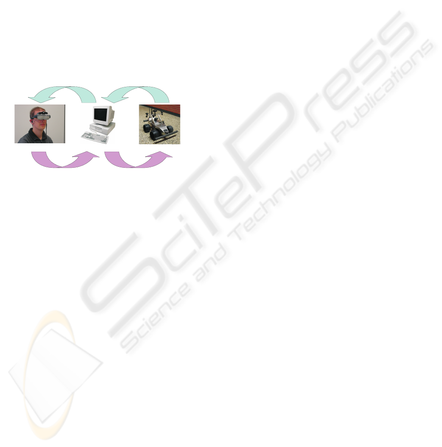
The system consists of two principal components:
the robot itself and an operator PC which acts as a
man machine interface to realize an intuitive interac-
tion with the radio controlled robot (see figure 1). To
achieve a full immersion, the information transfer be-
tween the operator and the remote environment via
the mobile platform and operator PC is of particular
importance. Not only the data acquisition must be
adapted to the human perception but a suitable pre-
sentation of the information is also necessary.
HMD,headset,forcefeedback WLAN,R8232andvideoradiolink
headtracker,joystick,steeringwheel RS232radiolink,WLAN
Operator OperatorPC Mobileplatform
Figure 1: Structure of TSR system.
For a realistic simulation, the integrated sensors
and the kinematics have to be modeled in our frame-
work. Furthermore, we motivate the use of different
interfaces for controlling the simulated robot.
The robot comprises several sensors (e.g. a stereo
camera and proximity sensors) and actuators (e.g.
pan-tilt unit of the camera head). The acquired data
is transmitted to the operator PC via different radio
links.
3.1 Control Interfaces
As motivation for the design of the desired control
interfaces in the simulation environment, we shortly
present the interfaces for the TSR.
First, there is an intuitive man machine interface:
the stereo images enhanced with further information
are presented to the operator on a head mounted dis-
play (HMD). So, for the simulation framework we re-
quire a manual control interface and a head tracker.
Furthermore, we have to display a virtual stereo im-
age pair on the HMD.
Secondly, we have input devices for the control of
the robot: a steering wheel and a joystick both with
force feedback characteristic. These input devices
transfer tactile information. In this way, vibrations of
the robot or centrifugal forces as well as approaches
to obstacles are directly transferred into force actions
for the input devices, providing a deeper immersion
of the operator and a more realistic driving situation.
Thus, we need an interface for such manual input de-
vices as well.
The aforementioned interfaces are required for
the tele operated mode. In its autonomous mode,
the robot’s sensor and actuators can be controlled
by an action planning module. The robot is e.g.
able to show visual attention while actively explor-
ing the environment. For this purpose, we have to
provide a software interface for controlling the virtual
robot by another system such as an artificial atten-
tion model. First results are described in (Aziz et al.,
2006) and (Shafik and Mertsching, 2007).
4 SIMULATION FRAMEWORK
SIMORE
The goal of our simulation framework is to simulate
robots and their environments with respect to the eval-
uation of image processing algorithms and navigation
strategies. It is completely implemented in C++ and
mostly independent from any operating systems ex-
cept the 3ds max plug-ins. The performance depends
on the used graphics card. Its object model is based on
the principle of design patterns (Gamma et al., 1997).
Its structure has a modular nature and the framework
offers a simple API to an unskilled programmer for
developing an external application based on a com-
plex robotic scenario or a simple test image demand.
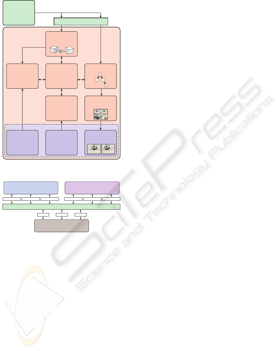
The SIMORE framework consists of several com-
ponents which will be described in detail in this sec-
tion. Figure 2 shows a functional diagram of these
components. The simulation component represents
the dynamic engine for collision detection and force
based physics. The scene graph component encapsu-
lates a scene graph and camera models. It is the 3D
graphics engine which forms the base of the visualiza-
tion component that provides the scene rendering and
much more capabilities (e.g. image read back func-
tionality of the camera sensor). Window system, API
and scheduled events will be processed in the event
handling. The API in context with possible applica-
tions is shown in figure 3.
On the basis of the simulation component the sen-
sor handling calculates the values of all available sen-
sors. The synchronization component keeps all other
components synchronized and defines the time-base
for the simulation.
MODELING AND SIMULATING MOBILE ROBOT ENVIRONMENTS
337
ODE
Physics
Simulation
OSG
SceneGraph
3DStudioMax
Modeling
Robots,Sensor,
ActorsandScenes
EventHandling
Joystick
Head Tracker
CameraControl
ServoControl
EventScheduler
SensorHandling
InfraRedSensor
U
GPSSensor
VelocitySensor
Compass
ltraSonicSensor
Synchronization
Synchronize
EventandSensor
Handling, Physics
andVisualization
SIMORE API
Image
Synthesization
left
right
SensorRequest
SensorValues
Control
Commands
RobotControl
ObjectControl
CameraSensor
Readback
Visualization
SIMOREFramework
OSGPlug-in
Figure 2: Functional diagram of SIMORE.
Images
Actors
Sensors
Applicationon
visualandroboticbehavior
HardwarePlatform
NaturalEnvironment(NE)
Transparent APIforMobileRobots,Sensorsand Actors
VirtualSensors Virtual Actors VirtualImagesRealSensors Real Actors RealImages VirtualSensors Virtual Actors VirtualImages
SIMORE API
VirtualEnvironment(VE)
Figure 3: Transparent API provides support for real and vir-
tual robots, sensors and actors.
4.1 Scene Modeling
The simulator is based on the open source library
OpenSceneGraph (Burns and Osfield, 2004) which is
a hierarchical graph that contains all drawable meshes
in a forward kinematic order. The project is based
on OpenGL and supports shader languages such as
the OpenGL Shader Language or NVidia’s CG. It is
a multi threaded library that has its own window han-
dling via OpenProducer. Other window systems such
as Trolltech’s QT and Microsoft’s MFC are supported
as well.
OpenSceneGraph’s so-called NodeKit enables the
possibility to extend it with several graph nodes to im-
plement any kind of datasets and functionalities. Our
goal was to include the required physical descriptions
as collision bodies and dynamic parameters such as
mass and mass inertia. We created nodes for joint
coupling of various types described in the physics
part. Some extra nodes for sensor and meta informa-
tion have been included as well.
The enhancement of the existing scene graph al-
lows us to rely on an existing library and an additional
open source project that handles export from 3ds max
called OSGExp. This project was extended with our
nodes so that developers are able to edit whole scene
data in 3ds max with physical and sensorial parame-
ters. The NodeKit consist of three libraries, the main
node kit library, an export-import library for Open-
SceneGraph and finally an object library for 3ds max.
4.2 Dynamic Simulation
Simulating a dynamic scene means simulating the oc-
curring physical processes next to the generation of
virtual images. The necessary computations for this
are accomplished by a physics engine. By means of
such a simulation e.g. statements about the possible
behavior of a robot in the real world can be met. For
the physics simulation in SIMORE the Open Dynam-
ics Engine is used which is an open source library for
simulating rigid body dynamics (Smith, 2007). For
providing and simulating a dynamic scene, ODE of-
fers a large number of features such as the integration
of different connecting joints, assigning masses and
mass distributions, creating geometric hulls for colli-
sion detection and much more. In the following, we
illustrate the various features using the virtual model
of the TSR.
A typical scene generally consists of an accumula-
tion of static (walls, cabinets, ...) and dynamic objects
(robot, balls, ...). The starting point of the structure of
such a scene is the model of a dynamic world and
setting its global physical dimensions such as gravita-
tion. The physical characteristics of an object are de-
scribed in ODE by Bodies. A body contains informa-
tion about the mass, the emphasis as well as informa-
tion about its position and rotation in the virtual area.
By effect of forces on a body, for example gravity, the
dynamic behavior of the bodies can be calculated. Af-
ter each simulation step the position of a body can be
obtained to draw a 3D model at this place.
Further bodies can be connected among them-
selves by means of joints. Several different connect-
ing joints are offered by ODE such as slider joints,
which permit only a movement along a given axes,
hinge joints for connections with one or two rota-
tion axes, ball joints for rotations around all three
axes or fixed joints for fixed connections between two
rigid bodies. However, bodies contain no information
about their geometrical structure. Thus no statement
on a collision between two bodies can be made. This
GRAPP 2008 - International Conference on Computer Graphics Theory and Applications
338
computation is fulfilled by the collision detection.
4.3 Collision Detection
Collision detection is a matter of recognizing the con-
tact or the penetration of two bodies. In ODE, these
bodies are called Geoms which describe the spatial
form of an object. Geoms can be placed in a virtual
space or can be assigned to bodies. The computa-
tion of collisions for complex geometric objects is a
very time-consuming task. In order to keep the cost
of computation as low as possible the geometries for
the collision computation are simple primitives (e.g.
box, sphere, cylinder, . . . ) in contrast to the complex
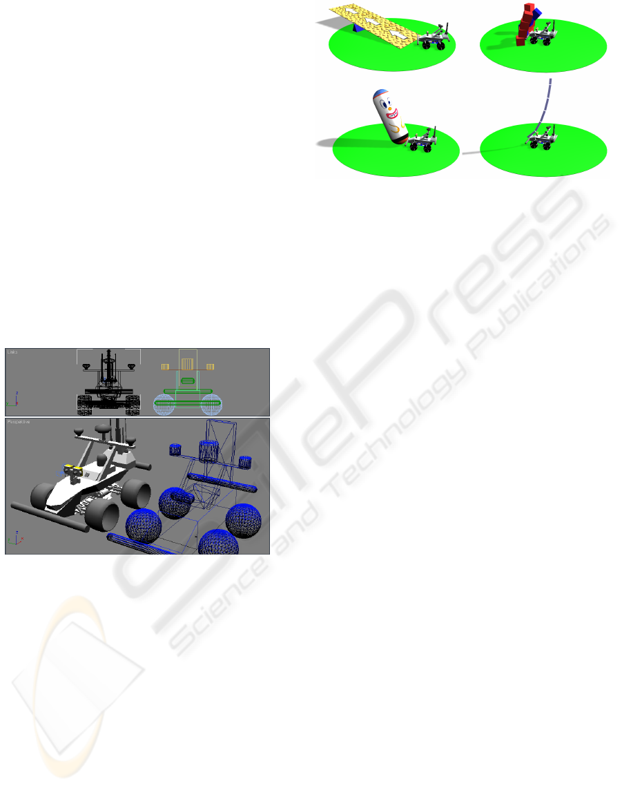
graphical objects. As an example, we chose the com-
putation of the tires as spheres because it is one of
the fastest collision computations in ODE. In figure 4
the TSR model is presented in 3ds max as a visual
representation with more than 5.000 polygons (solid
model) and as collision model which consists of 15
primitives (wireframe model).
Figure 4: Modeling of collision objects in 3ds max.
In order to give the users a possibility to simply
create their own physics model we implemented a
3ds max plug-in with which a given 3D model can
be extended with physical components. Like the 3D
model the physics model can be constructed by the
GUI (graphic user interface) of 3ds max. The mod-
eling of the physical objects is as simple as the mod-
eling of 3ds max objects. Further information such
as mass or friction can be specified with these ob-
jects. Finally, all objects will be connected to each
other in a hierarchical model which can be exported
to the OpenSceneGraph file format.
In figure 5 a few examples are shown that have
been created in 3ds max and which can be exported
to be used in the simulator (dynamic objects during
collision, chained objects and objects with displaced
center of gravity (skipjack)).
Figure 5: Possible dynamic behaviors implemented in
SIMORE.
4.4 Camera Sensor Read Back
As mentioned before we use OpenSceneGraph for
representing the hierarchical world model. In the
scene graph and visualization components the scene
graph is handled and used for generating sensor infor-
mation and viewing images. One camera sensor for
single view or two camera sensors for stereo view can
be simulated by the camera perspectives from device
views based on camera models. The different cam-
era perspectives of the acting robots can be rendered
into graphics memory and transferred afterwards into
main memory or for later processing on hard disk
(read back). Thus, it is possible to have different cam-
era sensor views in the scene and a view from an in-
dependent perspective in the application window. In
figure 6 an example for different views is presented.
Furthermore, the stereo view which shows the visual
information acquired by the robot platform has been
changed by simple image processing algorithms.
For the realization of the read back functional-
ity different methods can be implemented. Hard-
ware accelerated offscreen rendering techniques such
as frame buffer objects (FBO) and pixel buffers
(PBuffer) can be easily used within OpenSceneGraph.
These OpenGL extensions provide buffers which can
act as render targets, e.g. textures (render-to-texture).
The content of the textures can be read back and im-
ages can be created. PBuffers have a disadvantage be-
cause they depend on the used operation system and
require a render context switch which reduces the per-
formance significantly. Another way to read back im-
ages from the graphics memory, which we use in our
framework, is to use the frame buffer of the appli-
cation with multiple viewports. The different view-
ports are placed behind each other in the direction
of their rendering order (from back to front) so that
the camera sensor outputs can be read back immedi-
ately. Finally, the global view of the scene will be ren-
dered into the main viewport which covers all other
MODELING AND SIMULATING MOBILE ROBOT ENVIRONMENTS
339
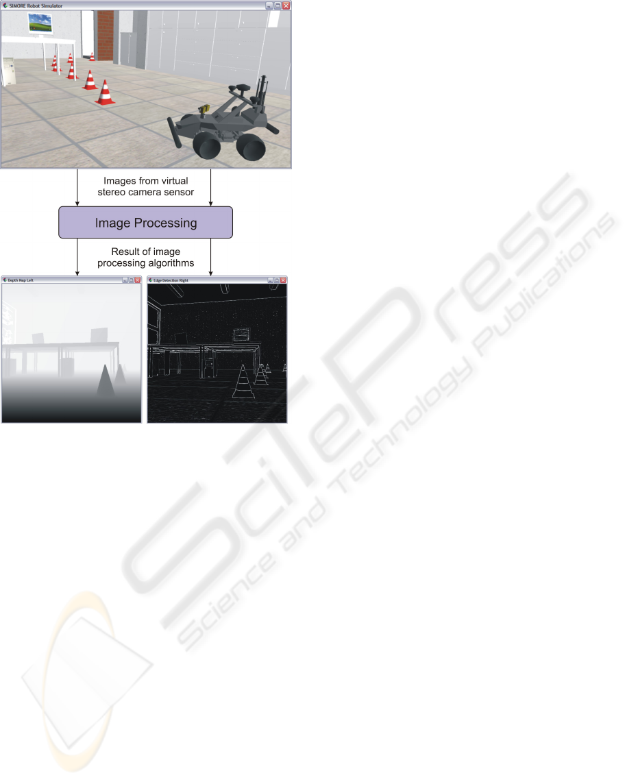
Figure 6: Stereo view of the robot’s virtual camera sensor.
viewports of the sensors’ output. OpenSceneGraph
provides a functionality to render the scene directly
into image objects which are accessible even after the
main viewport has been rendered.
4.5 Additional Components
For testing navigation strategies or visual attention al-
gorithms we will offer a plug-in interface that is at
least time-based benchmarkable and can be attached
to the sensor equipment. This interface will dynam-
ically load the plug-in library and apply its process-
ing methods on data events such as the next simula-
tion step. By offering users a simple implementation
method it should be possible to use the simulator for
educational and scientific purposes.
The used physics library does not support trans-
mission of motors and servos so we need a time de-
pendant controlling model for the simulator. This will
be solved by having a controller model that allows the
attachment of transform functions such as an output
curve of a motor. External or internal inputs such as
a motion API call or joystick will be transformed by
this function and allow a realistic behavior.
Therefore, we will implement a scheduler for ex-
ecuting events at specified times. This enables us
to have a programmable simulation that can be ex-
ecuted under changing conditions without changing
the source code.
4.6 Synchronization Concepts
A major problem in the simulator framework is keep-
ing all components synchronized. SIMORE itself
has a multi-threading architecture in which sensor
and control handling, simulation and visualization are
concurrent tasks that need to be synchronized. It is
in the responsibility of the synchronization module to
provide consistent data for the other tasks. For this
reason, changes to the actual situation due to internal
or external events must be propagated.
At the moment, only the simulation and visual-
ization components are synchronized because the vi-
sual representation depends on the simulation output.
Synchronizing the control and sensor handling is in
progress. Once it is developed the user can control
the robot manually by multiple input devices such as
mouse, joystick or force feedback steering wheel. So
far, the keyboard offers the only possibility for manu-
ally controlling the robot. An automatic control using
the API control function calls is also implemented.
In addition to the robots all other moveable objects
can be affected by the user in future. An object edi-
tor is under development to specify the objects’ visual
representation and to define their position and move-
ment. A major advantage compared to the real world
is the possibility of saving and reconstructing scenes
in a way that visual attention algorithms can operate
on equal terms and conditions.
5 CONCLUSIONS AND
DISCUSSION
In this contribution, we have presented a simulation
environment for mobile robot platforms. The main
advantages compared to existing robot simulators are
the variable control possibilities, the transparent in-
terface to the real robot TSR and the scene model-
ing technique using the modeling software 3ds max.
This method includes modeling of the collision ob-
jects, physical sensors and setting up hinges and joints
for dynamic simulation. So far, we have modeled the
TSR as a mobile platform in different virtual environ-
ments. But due to the hierarchical structure based on
OpenSceneGraph the framework is not limited to our
robot or the virtual environment. To date, we are able
to control our simulated robot manually via keyboard
GRAPP 2008 - International Conference on Computer Graphics Theory and Applications
340

or mouse actions. The development of the control
interface for the head tracker and the force feedback
steering wheel is still in progress.
Currently, we can provide visual information to
an operator, and due to the read back functional-
ity different perspective views are possible. Exper-
iments on NVidia graphics cards (NVidia 7600GT,
PCIe Bus) while rendering an image with an image
size of 512 × 512 pixels yield a frame rate of 42 fps
if transferring the images into the main memory and
22-28 fps for saving them on hard disc (depends on
the speed of the hard disk drive). Our goal is to ac-
celerate the performance by avoiding redundant copy
instructions on the GPU.
Future research concentrates on implementing a
scene editor to provide an intuitive graphical user
interface to users for generating their own scenes
with the required complexity without having deeper
knowledge of computer graphics. Another extension
for our environment is to model the visual or dynamic
features of additional robots (air robot, P3-AT) and to
integrate them into the simulation framework. Finally
we aim at a realization of a network access to the sim-
ulation framework so that a virtual robot platform can
be controlled via intranet or even internet.
REFERENCES
Aragon, C. R. and Hearst, M. A. (2005). Improving aviation
safety with information visualization: a flight simula-
tion study. In Proceedings of the SIGCHI conference
on Human factors in computing systems (CHI ’05).
Autodesk (2006). 3D Studio Max, Version 9.
http://www.autodesk.com/3dsmax.
Aziz, Z., Mertsching, B., Shafik, M., and Stemmer, R.
(2006). Evaluation of visual attention models for
robots. In Proceedings of IEEE International Con-
ference on Computer Vision Systems (ICVS2006).
Balakirsky, S., Scrapper, C., Carpin, S., and Lewis, M.
(2006). Usarsim: Providing a framework for multi-
robot performance evaluation. In Proceedings of the
Performance Metrics for Intelligent Systems Work-
shop, pages 0–1.
Burns, D. and Osfield, R. (2004). Tutorial: Open scene
graph. In Proceedings Virtual Reality, pages 265–265.
Carpin, S., Lewis, M., Wang, J., Balakirsky, S., and Scrap-
per, C. (2007). Usarsim: a robot simulator for research
and education. In ICRA, pages 1400–1405. IEEE.
Chen, K.-Z., Feng, X.-Y., Wang, F., and Feng, X.-A. (2007).
A virtual manufacturing system for components made
of a multiphase perfect material. Computer Aided De-
sign, 39(2):112–124.
Freund, E. and Pensky, D. (2002). Cosimir factory: ex-
tending the use of manufacturing simulations. In
Proceedings of the IEEE International Conference on
Robotics and Automation (ICRA ’02), volume 2, pages
2805–2810.
Gamma, E., Helm, R., Johnson, R., and Vlissides, J.
(1997). Design Patterns - Elements of Reusable
Object-Oriented Software. Addison-Wesley Profes-
sional.
Koenig, N. and Howard, A. (2004). Design and use
paradigms for gazebo, an open-source multi-robot
simulator. In Proceedings of IEEE/RSJ International
Conference on Intelligent Robots and Systems.
Leger, C. (2000). Darwin2K: An Evolutionary Approach
to Automated Design for Robotics. Kluwer Academic
Publishers.
Michel, O. (2004). Cyberbotics ltd - webots
T M
: Profes-
sional mobile robot simulation. International Journal
of Advanced Robotic Systems, 1(1):39–42.
Shafik, M. and Mertsching, B. (2007). Enhanced motion pa-
rameters estimation for an active vision system. In 7th
Open German/Russian Workshop on Pattern Recogni-
tion and Image Understanding.
Smith, R. (2007). Open Dynamics Engine, Version 0.8.
http://www.ode.org/.
Stellmann, P. (2003). Schnittstellenspezifikation und Ver-
haltenssimulation f
¨
ur ein System autonomer mo-
biler Roboter. Diplomarbeit, Technical University
Hamburg-Harburg.
Stemmer, R., Brockers, R., Dr
¨
ue, S., and Thiem, J. (2003).
Comprehensive data acquisition for a telepresence ap-
plication. In International Conference on Systems,
Man and Cybernetics (SMC04), pages 5344–5349.
Wang, R., Zhang, G., and Yang, P. (2005). Simulation of
vision based landing an uav on a ship. In Proceedings
of the 6th International Conference on System Simu-
lation and Scientific Computing (ICSC2005).
Zyda, M. (2005). From visual simulation to virtual reality
to games. Computer, 38(9):25–32.
MODELING AND SIMULATING MOBILE ROBOT ENVIRONMENTS
341
