CORE POINT DETECTION USING FINE ORIENTATION FIELD
ESTIMATION
M. Usman Akram, Rabia Arshad, Rabia Anwar, Shoab A. Khan
Department of Computer Engineering, EME College, NUST, Rawalpindi, Pakistan
Sarwat Nasir
Department of Telecommunication, MCS, NUST, Rawalpindi, Pakistan
Keywords:
Segmentation, Orientation Field, Poincare Index,Gradient, Optimal Core Point.
Abstract:
Performance of Automatic Fingerprint Identification System( AFIS) is greatly influenced by the detection of
core point. Extraction of best Region Of Interest(ROI) from image can play a vital role for core point detection.
In this paper, we present an improved technique for fine orientation field estimation and core point detection.
The distinct feature of our technique is that it gives high detection percentage of core point even in case of low
quality fingerprint images. The proposed algorithm is applied on FVC2004 database. Results of experiments
demonstrate improved performance for detecting core point.
1 INTRODUCTION
Fingerprints have been in use for biometric recogni-
tion since long because of their high acceptability, im-
mutability and individuality.
The probability that two fingerprints are alike is
1 in 1.9 x 10
15
(W. F. Leung and Luk, 1991). These
features make the use of fingerprints extremely effec-
tive in areas where the provision of a high degree of
security is an issue.
Most Automatic Fingerprint Identification sys-
tems (AFIS) are based on local ridge features;
ridge ending and ridge bifurcation, known as
minutiae(A.K Jain and Boole, 1997). Core points
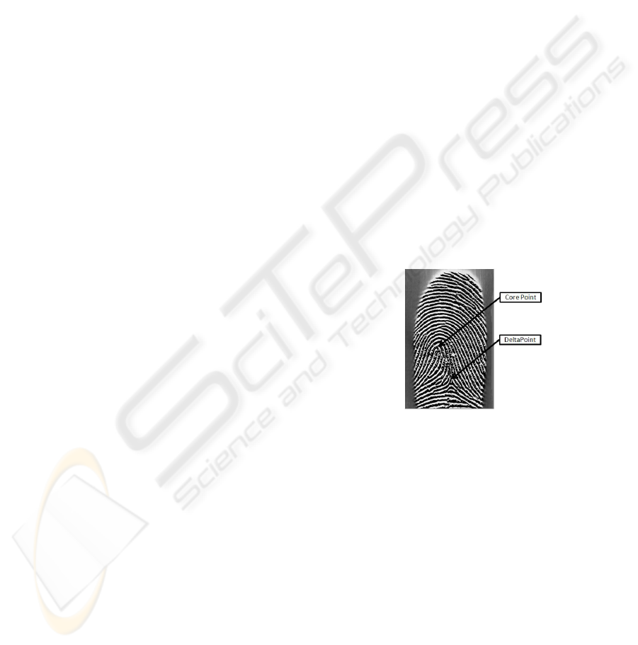
and delta points are critical points in fingerprint. Core
points are the points where the innermost ridge loops
are at their steepest and delta points are points from
which three patterns deviate (Anil Jain, 1998),(Zhang,
2000). Figure 1 shows the location of core point and
delta point in a fingerprint image.
In AFIS, core point plays an important role
(D. Maltoni and Prabhakar, 2003) and it is
widely used for fingerprint matching (Anil Jain,
1998),(D. Maltoni and Prabhakar, 2003),(Maio and
Maltoni, 1997) and classification (Wang and Wang.,
2004),(A. K. Jain and Hong, 1999),(Sen Wang, 2002).
The problem with applications related with finger-
print is how to fix the fingerprint with the help of
Figure 1: Core point and Delta point for a Fingerprint Im-
age.
a reference point so that it would be invariant to er-
ror generated by scanning process(Maio and Maltoni,
1997). This problem can be overcome by detect-
ing core point accurately. Minutiae based fingerprint
matching is widely used in AFIS (Maio and Maltoni,
1997),(Kalle Karu, 1996) where minutiae in neigh-
bor of core point also plays an important role in fre-
quency characteristic fingerprint matching (Maio and
Maltoni, 1997).
A number of algorithms have been proposed for
optimal core point detection and most of them are
based on ridge orientation estimation techniques. A
common method used for core point detection is
Poincare index in which point in the ridge orienta-
tion field is classified as singular point if orientation
along a small closed curve around that point changes
351
Usman Akram M., Arshaf R., Anwar R., Khan S. and Nasir S. (2008).
CORE POINT DETECTION USING FINE ORIENTATION FIELD ESTIMATION.
In Proceedings of the Third International Conference on Computer Vision Theory and Applications, pages 351-356
DOI: 10.5220/0001089503510356
Copyright
c
SciTePress

0,±180 or ±360 degrees(Kalle Karu, 1996). A.K.
Jain, S. Prabhakar, L. Hong and S. Pankanti had used
geometry of region technique in (Ani1 K. Jain and
Pankanti, 2000) for reference point detection. Chul-
Hyun Park, Joon-Jae Lee, Mark J.T. Smith and Kil-
Houm Park had proposed a method for reference point
detection especially for arch-type fingerprint.
This paper is organized in six sections. Section
2 deals with the preprocessing of fingerprint image
before locating the core point. Section 3 presents
Poincare index, Geometry of Region Technique and
Direction of Curvature technique while section 4 con-
tains the proposed technique and its algorithm. Com-
parative analysis of experimental results of our tech-
nique with other techniques are presented and dis-
cussed in section 5 followed by conclusion in section
6.
2 FRONT-END PROCESSING
Core point detection process is greatly effected by
quality of fingerprint image. Good image segmenta-
tion and orientation field estimation is required for op-
timal core point detection (Maio and Maltoni, 1997).
Figure 2 shows the sequence of steps required for op-
timal core point detection.
Figure 2: Sequential front-end processing for core point de-
tection.
2.1 Image Segmentation
Segmentation is done to extract fingerprint image
from background. In AFIS, the surrounding back-
ground in fingerprint image does not carry any infor-
mation and therefore add to the processing time of all
stages if included. The cutting and cropping out re-
gion containing fingerprint feature, commonly called
Region of Interest(ROI), from the fingerprint image
minimizes the computational time.
Steps for Mean and Variance Based fingerprint
image segmentation technique (Maio and Maltoni,
1997) are summarized as follows:
1. Divide the input image I(i, j) into non-
overlapping blocks with size w×w.
2. Compute the mean value M(I) for each block us-
ing equation 1.
M(I) =
1
w
2
w/2
∑
i=−w/2
w/2
∑
j=−w/2
I(i, j) (1)
3. Use the mean value computed in step 2 to com-
pute the standard deviation value std(I) with
equation 2
std(I) =
v
u
u
t
1
w
2
w/2
∑
i=−w/2
w/2
∑
j=−w/2
(I(i, j) − M(I))
2
(2)
4. Select a threshold value empirically. If the std(I)
is greater than threshold value, the block is con-
sidered as foreground otherwise it belongs to
background.
2.2 Image Normalization
Normalization is performed to remove the effect of
sensor noise and gray level background which are
the consequence of difference in finger pressure ap-
plied at the scanner (Kawagoe and A.Tojo, 1984). Let
I(i, j) denotes the gray-level value at pixel (i,j). The
normalized value N(i, j) for pixel (i, j)is defined in
equation 3 (Maio and Maltoni, 1997)
N(i, j) =
M
o
+
q
(V
o
(I(i, j))−M
i
)
2
V
i
if I(i, j) > M
M
o
−
q
(V
o
(I(i, j))−M
i
)
2
V
i
otherwise
(3)
Here M
0
and V
0
are the desired mean and variance
respectively. The mean M(I) and variance V (I) of
a gray-level fingerprint image with the dimension
of M × N pixels, are defined using equation 4 and 5
respectively (Maio and Maltoni, 1997).
M(I) =
1
MN
M−1
∑
i=0
N−1
∑
j=0
I(i, j) (4)
V (I) =
1
MN
M−1
∑
i=0
N−1
∑
j=0
(I(i, j) − M(I))
2
(5)
Where I(i, j ) represents the intensity of the pixel
at ith row and jth column. The basic objective
of normalization operation is to reduce the varia-
tions of gray-level values along the ridges and valleys
(A.K Jain and Boole, 1997).
2.3 Orientation Field Estimation
Orientation or direction field estimation is not only
used in core point detection but also in fingerprint
matching (A.K Jain and Boole, 1997). The smoothed
orientation field based on least mean square algorithm
(A.K Jain and Boole, 1997)(Maio and Maltoni, 1997)
is summarized as follows:
VISAPP 2008 - International Conference on Computer Vision Theory and Applications
352
1. Divide the input image I(i, j) into non-
overlapping blocks with size w x w.
2. Compute the gradients ∂
x
(i, j) and ∂
y
(i, j) at the
center of the block.
3. Estimate the local orientation using the equations
6, 7 and 8 (Maio and Maltoni, 1997).
V
x
(i, j) =
i+w/2
∑
u=i−w/2
j+w/2
∑
v= j −w/2
2∂
x
(u,v)∂
y
(u,v) (6)
V
y
(i, j) =
i+w/2
∑
u=i−w/2
j+w/2
∑
v= j −w/2
∂
2
x
(u,v)∂
2
y
(u,v) (7)
θ(i, j) =
1
2
tan
−1
V
y
(i, j)
V
x
(i, j)
(8)
Here θ(i, j) is the least square estimate of the lo-
cal ridge orientation at the block centered at pixel
(i, j).
4. The local ridge orientation varies slowly in a lo-
cal neighborhood where no core point appears.
The discontinuity in ridge and valley due to noise
can be reduced by applying a low pass filter.
However, to apply a low pass filter the orienta-
tion image must first be converted to a Contin-
uous Vector Field (CFV). The continuous vector
field is defined by the x-component Φ
x
and the y-
component Φ
y
computed using equation 9 and 10
respectively (Maio and Maltoni, 1997).
Φ
x
(i, j) = cos(2θ(i, j)) (9)
Φ
y
(i, j) = sin(2θ(i, j)) (10)
5. The two dimensional w
Φ
w
Φ
low-pass filter G
with unit integral is applied to the resultant CFV.
The filtered x-component and y-component of the
CFV are obtained by equations 11 and 12 respec-
tively (Maio and Maltoni, 1997).
Φ
0
x
(i, j) =
w
Φ
/2
∑
u=−w
Φ
/2
w
Φ
/2
∑
v=−w
Φ
/2
G(u,v)Φ
x
(i − uw, j − vw)
(11)
Φ
0
y
(i, j) =
w
Φ
/2
∑
u=−w
Φ
/2
w
Φ
/2
∑
v=−w
Φ
/2
G(u,v)Φ
y
(i − uw, j − vw)
(12)
6. The smoothed orientation field at (i, j) is com-
puted by equation 13 (Maio and Maltoni, 1997).
θ
0
(i, j) =
1
2
tan
−1
Φ
0
y
(i, j)
Φ
0
x
(i, j)
(13)
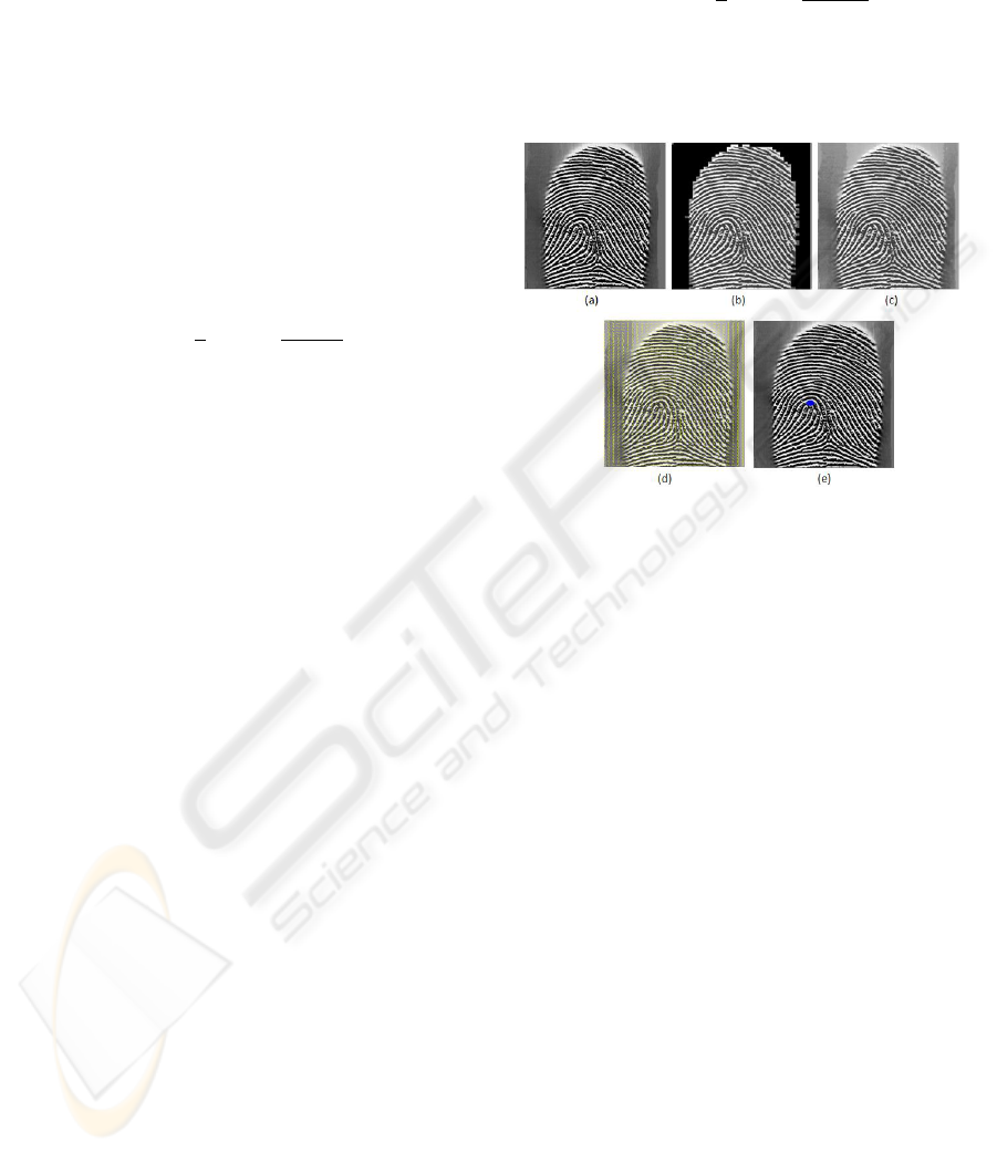
Figure 3 shows segmentation, normalization, ori-
entation estimation and core point detection for a fin-
gerprint image.
Figure 3: (a) Original image (b) Segmented image (c) Nor-
malized image (d) Orientation estimation (e) Detected Core
point.
3 CORE POINT DETECTION
TECHNIQUES
The core point is used in both fingerprint classifica-
tion and fingerprint matching using either spatial do-
main (A.K Jain and Boole, 1997)(Ani1 K. Jain and
Pankanti, 2000) or transformed domain (Ani1 K. Jain
and Pankanti, 2000). This section details different
techniques for core point detection.
3.1 Geometry of Region Technique
(GR)
It is very important to find the geometry of region to
detect core point as the ridge line curvature varies
sharply near core point region (Maio and Maltoni,
1997).
The GR technique can be summarized as follows.
1. Compute the smoothed orientation field θ
0
(i, j)by
using equation 13 above.
2. Compute ε(i, j) from equation 14 (Maio and Mal-
toni, 1997), which is the sine component of θ
0
(i, j)
ε(i, j) = sin(θ
0
(i, j)) (14)
CORE POINT DETECTION USING FINE ORIENTATION FIELD ESTIMATION
353

3. Initialize a label image A which is used to indicate
the core point.
4. Assign the corresponding pixel in the value of
the difference in integrated pixel intensity of each
region A from equation 15 (Maio and Maltoni,
1997).
A(i, j) =
∑
R
1
ε(i, j) −
∑
R
2
ε(i, j) (15)
The regions R1 and R2 are determined empiri-
cally and also their geometry are designed to cap-
ture the maximum curvature in concave ridges and
should cover at least one ridge.
5. Find pixel (i, j) that have maximum value in A
and assign it as the core point.
6. If the core point still cannot be located, the steps
(1-5) could be iterated for a number of times while
decreasing the window size used in step 1) above.
3.2 Poincare Index
An elegant and practical method based on the
Poincare index was proposed in (Kawagoe and
A.Tojo, 1984). The PC technique can be summarized
as follows (Maio and Maltoni, 1997),(Sen Wang,
2002).
1. Estimate the orientation field θ
0
(i, j) by using
the least square orientation estimation algorithm
given by equation 13 (Maio and Maltoni, 1997)
above.
2. Initialize a label image A which is used to indicate
the core point.
3. For each pixel, compute Poincare index, PC(i, j)
from 16, 17 and 18 (Kawagoe and A.Tojo, 1984)
where
PC(i, j) =
1
2π
N
p
−1
∑
k=0
∆(k) (16)
∆(k) =
δ(k) if δ(k) < π/2
π + δ(k) if δ(k) ≤ −π/2
π − δ(k) otherwise
(17)
and
δ(k) = ε(x
(k+1)
modN
p
,y
(k+1)
modN
p
)− ε(x
k
,y
k
) (18)
4. The core point should yield the Poincare index be-
tween 0.45-0.51 (Kawagoe and A.Tojo, 1984).
5. The center of the block with the value of one is
considered to be a core point. However if there are
more than one block with that values, the average
calculation is applicable.
3.3 Detection of Curvature Technique
1. Compute the local orientation θ(i, j) by using
equation 8 (Maio and Maltoni, 1997). The input
block size is kxk = 3x3.
2. Smooth the orientation field θ
0
(i, j) by using equa-
tion 13 (Maio and Maltoni, 1997).
3. The difference of direction components is com-
puted for every progressive block from equations
19 and 20.
Di f fY =
3
∑
k=1
sin2θ(k, 3) −
3
∑
k=1
sin2θ(k, 1) (19)
Di f f X =
3
∑
k=1
cos2θ(3,k) −
3
∑
k=1
cos2θ(1,k) (20)
4. The core point could be located at the correspond-
ing (i, j) where Di f f X and Di f fY are negative.
4 PROPOSED TECHNIQUE
In our proposed method, segmentation and Normal-
ization are done in the same way as described in
section 2 while orientation field is estimated by new
method as it greatly effects the core point detection.
4.1 Fine Orientation Field Estimation
The steps for proposed technique are summarized as
follows
1. Divide the input image I(i, j) into non-
overlapping blocks with size w x w. In our
case w = 16.
2. Use 3x3 sobel vertical and horizontal masks from
equations 21 and 22 to compute the gradients
∂
x
(i, j) and ∂
y
(i, j) at each pixel (i,j) respectively
which is the center of the block.
sobelHorizontal =
−1 0 1
2 0 2
−1 0 1
(21)
sobelVertical =
−1 −2 −1
0 0 0
1 2 1
(22)
3. Estimate the local orientation using equations 23,
24 and 25 (Lim and S.Jae, 1990).
VISAPP 2008 - International Conference on Computer Vision Theory and Applications
354
V
x
(i, j) =
i+w/2
∑
u=i−w/2
j+w/2
∑
v= j −w/2
(∂
x
(u,v))(∂
y
(u,v))
(23)
V
y
(i, j) =
i+w/2
∑
u=i−w/2
j+w/2
∑
v= j −w/2
∂
2
x
(u,v)−∂
2
y
(u,v) (24)
V
z
(i, j) =
i+w/2
∑
u=i−w/2
j+w/2
∑
v= j−w/2
(∂
x
(u,v) + ∂
y
(u,v))
2
(25)
4. Calculate background certainty and orientation
field using equation 26 and 27 respectively
(Zhongchao Shi and Xu, 2004).
coh =
s
(V
2
x
(i, j) +V
2
y
(i, j))
w
2
∗V
z
(26)
ifcoh > 10then
θ(i, j) =
π
2
+
1
2
tan
−1
2V
x
(i, j)
V
y
(i, j)
(27)
4.2 Optimal Core Point Detection
Steps for our core point detection technique are sum-
marized as follows:
1. Compute the local orientation θ(i, j) by using
equation (27) . The input block size is kxk = 3x3.
2. Locate the region of interest (ROI) based on back-
ground certainty
3. Initialize a label image A which is used to indicate
the core point.
4. Apply steps 3 and 4 on ROI from Poincare Index
technique
5. Find each connected component in A with pixel
values 1. There is normally more than one objects.
Core Point object will always have the largest
area. So we first figure out the object having the
largest area.
6. Then we calculate the centroid of the selected ob-
ject. This centroid gives us the location of core
point.
5 EXPERIMENTAL RESULTS
The performance of our modification is tested on
FVC2004 database(FVC, 2004).The database con-
tains 40 different fingers and 8 impressions of each
finger (40x8=320 fingerprints). The images in
DB1, DB2, DB3 and DB4 are 640×480, 328×364,
300×480 and 288×384 respectively and each hav-
ing a resolution of 500 dpi. For all fingerprint im-
ages core points are detected ideally. Euclidian dis-
tances between ideally detected core points and core
points detected from discussed techniques are calcu-
lated. The core point detection results are compared
and they are summarized in table 1 and table 2.The
decision for accepted location (Accepted Core Point,
ACP) and false location (False Core Point, FCP) is
based on euclidian distances. For all methods maxi-
mum, minimum,mean and standard deviation of error
is calculated. Table 3 shows error performance and
are defined in terms of number of pixels. For above
mentioned techniques ,a comparative analysis of the
computation time, with AMD, 801 MHz, and 1 GB
RAM, is summarized in table 4.
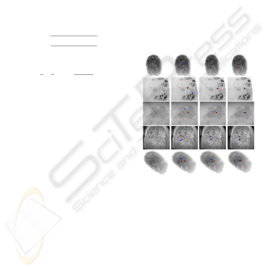
Figure 4: Pictorial comparison of proposed algorithm with
traditional techniques. Ist column shows the original fin-
gerprint images. 2nd and 3rd columns show the results of
Poincare index and Detection of curvature techniques re-
spectively. 4th column show the results of proposed algo-
rithm.
Figure 4 shows the comparison of the proposed
technique with the ones discussed in (Maio and Mal-
toni, 1997),(Maio and Maltoni, 1997),(Kawagoe and
A.Tojo, 1984). Red dot shows the ideal core point
location while the blue dot shows the detected core
point. Figure 5 shows that proposed technique detects
core point correctly even in case of very oily and dry
fingerprint images.
CORE POINT DETECTION USING FINE ORIENTATION FIELD ESTIMATION
355
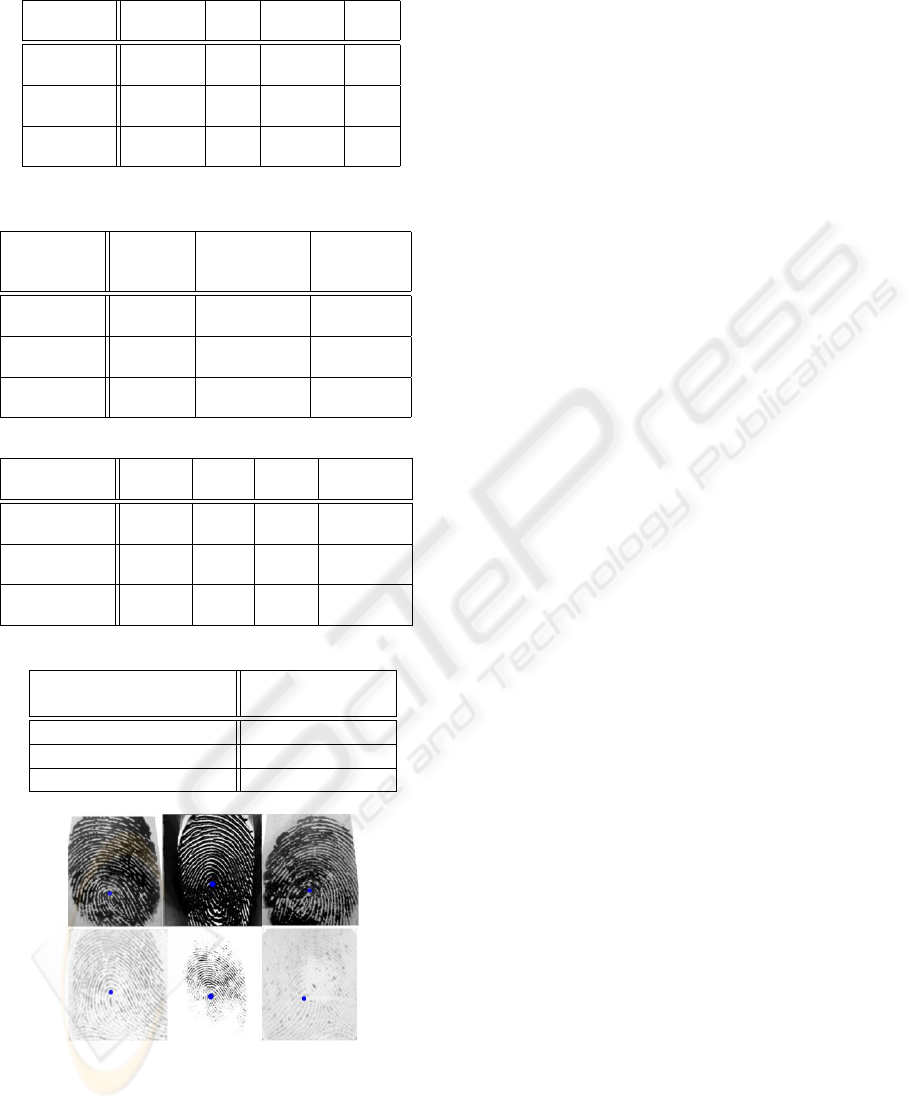
Table 1: Evaluation Core Point Detection for FVC2004.
ACP ACP FCP FCP
Approaches (Numbers) (%) (Numbers) (%)
Poincare
Index 191 59.68 129 40.32
Detection
of Curvature 263 82.18 57 17.82
Optimal
Core Point 293 91.56 27 8.44
Table 2: Performance Evaluation of Core Point Detection
for Different Quality Images.
Fingerprint Poincare Detection Optimal
Image Index of Curvature Core Point
Quality (%) (%) (%)
Good
Quality 90.3 94.8 98.7
Low
Quality 50.1 63.4 82.3
Rotated
Images 57.8 71.2 87.1
Table 3: Error Performance Evaluation.
Max Min Mean Std
Techniques Error Error Error Deviation
Poincare
Index 240.98 0 25.51 37.75
Detection
of Curvature 240.98 0 22.73 36.01
Optimal
Core Point 240.98 0 14.75 34.39
Table 4: Evaluation of Computational Time.
Processing Time
Techniques Seconds
Poincare Index 0.45
Detection of Curvature 0.25
Optimal Core Point 0.18
Figure 5: 1st row: Oily fingerprint images, 2nd row: Dry
fingerprint images.
6 CONCLUSIONS
Our core point detection technique is useful as it de-
tects the optimal core point with low computation and
it requires simple field orientation. Optimal core point
is detected using the fine orientation field estimation.
The performance of the proposed technique is better
than the Poincare index and Detection of Curvature
technique. Moreover the proposed technique gives
better results even in case of oily and dry images.
REFERENCES
A. K. Jain, S. P. and Hong, L. (1999). A multichannel ap-
proach to fingerprint classification. In IEEE Transac-
tions on PAMI, Vol.21, No.4, pp. 348-359.
A.K Jain, H. L. and Boole, R. (1997). One-line finger-
print verification. In IEEE Trans. PAMI, Vol.19,No.4,
pp.302-314.
Ani1 K. Jain, Salil Prabhakar, L. H. and Pankanti, S.
(2000). Filterbank-based fingerprint matching. In
IEEE Transactions on Image Processing, Vol. 9, No
5, pp. 846-859.
Anil Jain, Ruud Bolle, S. P. (1998). Biometrics-personal
identification in networked society. In KluwerAca-
demic Publishers, pp 411.
D. Maltoni, D. Maio, A. K. J. and Prabhakar, S. (2003).
Handbook of fingerprint recognition. In Springer-
Verlag.
FVC (2004). Finger print verification contest 2004. In
Available at (http://bias.csr.unibo.it/fvc2004.html).
Kalle Karu, A. J. (1996). Fingerprint classification. In Pat-
tern Recognition, vol. 18, No.3, pp.389-404.
Kawagoe, M. and A.Tojo (1984). Fingerprint pattern classi-
fication. In Pattern Recognition, Vol.17, pp.295-303.
Lim and S.Jae (1990). Two-Dimensional Signal Image Pro-
cessing.
Maio, D. and Maltoni, D. (Jan 1997). Direct gray-scale
minutiae detection in fingerprints. In IEEE Trans. on
Pattern Analysis and Machine Inteligence, vol. 19, pp.
27-40.
Sen Wang, Wei Wei Zhang, Y. S. W. (2002). Fingerprint
classification by directional fields. In Proceedings of
the Fourth IEEE International Conference on Multi-
modal Interfaces (ICMI’02).
W. F. Leung, S. H. Leung, W. H. L. and Luk, A. (1991).
Fingerprint recognition using neural network. In Neu-
ral Networks For Signal Processing - Proceedings Of
The 1991 IEEE Workshop.
Wang, S. and Wang., Y. (2004). Fingerprint enhancement
in the singular point area. In IEEE signal processing
letters, vol. 11, no. 1, pp. 16-19.
Zhang, D. D. (2000). Automated biometrics technologies
and systems. In Kluwer Academic Publishers, pp.331.
Zhongchao Shi, Yangsheng Wang, J. Q. and Xu, K. (2004).
A new segmentation algorithm for low quality finger-
print image. In IEEE Proceedings of the Third Inter-
national Conference on Image and Graphics.
VISAPP 2008 - International Conference on Computer Vision Theory and Applications
356
