
MULTIPARAMETER SINGLE LOCUS INTEGRATED
MULTILAYER POLYMER MICROSENSOR SYSTEM
Yindar Chuo and Bozena Kaminska
School of Engineering, Faculty of Applied Science, Simon Fraser University, 8888 University Drive, Burnaby, Canada
Keywords: Biosensor, multiparameter, microintegration, flexible polymer system-in-package, MEMS, health
monitoring, wireless senor, cardio health monitoring.
Abstract: Miniaturization and microintegration is well known for their potentials in providing microsystems and
sensors with unmatched performance, reliability, and lower costs. Current technologies in implementation
of microsensors, however, span a large variety of platforms. It is thus common for microsensors measuring
differing parameters to exist on different combinations of substrates, not to even mention the associated
signal conditioning, processing, and data communication electronics. It remains a challenge to integrate
multiple sensors with complex electronics into a single high-density microsystem, particularly for certain
applications in medical diagnostics and healthcare, where mechanical flexibility of the substrate and
biocompatibility also becomes crucial considerations. Traditional microintegration technologies such as
system-in-package, system-on-chip, and advanced assembly and packaging, may often be inadequate. A
mutliparameter single locus integrated multilayer polymer microsensor system is proposed to address the
fundamental issues of high-density integration, flexibility, biocompatibility, easy application, high
sensitivity, and reliability for medical grade diagnostics and other physiological applications. The
architecture of the multilayer system is discussed, as well, implementation and fabrication of the
multisensor layer is demonstrated, and the results on performance discussed.
1 INTRODUCTION
Miniaturization and microintegration of sensors
through novel microelectronics and
microelectromechanical systems (MEMS)
technologies have demonstrated large potentials in
providing unmatched performance, reliability, and
cost effectiveness (Wang, 2002) over the recent
years in many applications. Particularly, in
applications involving physiological monitoring and
healthcare, microintegrated sensors have been able
to provide the combination of high analyte
sensitivity, electrical responsiveness, precise
temporal control, small feature sizes, and low power
consumption, that otherwise is often very difficult to
achieve through traditional technologies (Richards
Grayson, 2004).
Current technologies in miniaturization of
sensors span a large domain. Much research has
focused on microfabrication of sensors through
microelectronics and MEMS (Richards Grayson,
2004). Methods in fabrication include various
lithographic techniques, stereolithography,
lithographie galvanoformung abformung (LIGA),
and micro injection molding, to just name a few.
Processes are often different and specific to each
type of microsensor. As a result, integration of
various microsensors and microelectronics is
difficult.
Thus far, technologies for microintegration
include system-on-chip (SoC) (Kundert, 2000),
system-in-package (SiP) (Matthews, 2003), and
advanced assembly and packaging (Fraunhofer
Institut Zuverlassigkeit und Mikrointegration). SoC
concepts allow designers to combine sensors and
system electronics on the same substrate, on a single
chip. An example is the popular lab-on-chip
technologies (Pai, 2001); however, often in
biological and environmental applications, it is
inherently difficult to design sensors on the same
substrate as the remaining electronic system (Zhang,
2007). SiP technology provides integration of
multiple sensors and system electronics from
differing substrates at the board level. Commonly,
unpackaged chips are placed and connected on one
single substrate or printed circuit board (PCB). This
36
Chuo Y. and Kaminska B. (2008).
MULTIPARAMETER SINGLE LOCUS INTEGRATED MULTILAYER POLYMER MICROSENSOR SYSTEM.
In Proceedings of the First International Conference on Biomedical Electronics and Devices, pages 36-43
DOI: 10.5220/0001047200360043
Copyright
c
SciTePress
allows for a high-density integrated system, but is
often limited by its rigid integration substrate, and
board ‘real-estate’.
In this paper, a multiparameter single locus
microintegrated sensor system is proposed for, but
not limited to, cardiac physiological signal
acquisition in diagnostics and health monitoring.
This novel integration technology platform proposes
higher density integration through multilayering of
mechanically flexible polymer substrates, while
providing a thin flexible profile for skin tissue
conformity. A complete system including multiple
microsensors, filtering, digitization, processing, and
communication electronics is proposed. In this
manner, the microintegration platform provides
advantages of high sensitivity, high actuation-to-
sensor coupling, and noise reduction through local
filtering and immediate digitization, for a system
that can provide medical diagnostic grade precision,
yet is flexible, compact and robust.
One particular implementation includes a surface
biopotential electrode integrated along with a
MEMS 3-axis accelerometer and signal filtering
electronics all together forming the multiparameter
sensor layer of the multilayer system. In this
implementation, parameters of interest include
electric potential and motion of the heart, recorded
simultaneously, in what is known as
ballistoelectrocardiography (BECG).
2 MULTIPARAMETER SENSOR
SYSTEM ARCHITECTURE
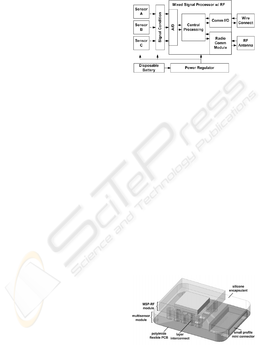
The multiparameter single locus integrated
multilayer sensor system consists of five functional
groups (Figure 1); the multisensors, signal
conditioning, microprocessor, communication
terminals, and powering. Multiple sensors acquire
signals of different parameters, and convert the
signals to electrical outputs. The signals are
conditioned through appropriate filters and
amplifiers, as close to the sensing elements as
possible, to minimize noise. Signals are then routed
to the mixed signal microprocessor (MSP) where it
is digitized, processes, and transmitted through radio
or wired communication portals. The system is
powered through either permanent or disposable
micro-batteries.
Figure 1: Modules of the integrated sensors system.
The conceptual assembly of the system is shown in
Figure 2. The system consists of two layers, with
option to be detachable from each other, and is
connected through columnar interconnects. Each
layer is composed of a flexible substrate (e.g.
polyimide), on top of which the electronic system is
placed and routed. Intermediate and encapsulating
each layer is a flexible material (e.g. silicone) acting
as insulation, structural support, and mechanical
protection. The intermediate layer can be shaped and
is electrically patternable such that electrical
interconnects, inter-layer attachment anchors, and
sensing element windows can be designed.
Here, with reference to both Figure 1 and Figure
2, the multiple sensors and signal conditioning
electronics are shown on the lower layer, which
allows the sensing elements to be closer to their
corresponding physiological actuations. Also
situated on the lower layer is a mini-connector for
applications requiring wired connections. The MSP
with build-in radio-frequency (RF) communication
module and the RF antenna are both placed on the
upper layer. Signals from the conditioning module
on the bottom layer are routed to the processor on
the top layer through the interconnects. Signals
between the processor to and from the wired
connection are also routed through the interconnects.
Figure 2: The multiparameter single locus integrated
multilayer polymer microsensor system.
MULTIPARAMETER SINGLE LOCUS INTEGRATED MULTILAYER POLYMER MICROSENSOR SYSTEM
37
Another important part of the integrated
multilayer sensor system is the attachment
mechanism to a subject surface. Since the integrated
multilayer sensor system is designed to be flexible,
with a low profile, to conform well to the contours
of human skin surface, the attachment mechanisms
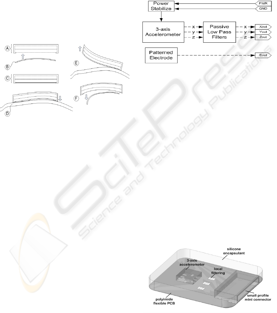
must not alter this feature. Figure 3 shows how the
integrated multilayer sensor device is conceptually
applied to a subject tissue surface by attachment of a
novel disposable adhesive. This disposable adhesive
must be very thin, attachable on both sides and
conductive at portions where it is required.
Figure 3: Application of integrated sensor device with
novel disposable adhesive: The integrated sensor device
(A) is attached on the bottom side with the disposable
adhesive (B) forming a ready-to-apply device (C), where
then it can be attached to subject skin surface (D) with
high conformity. Device is removed from subject by
simply pealing (E) off from attached surface, while
disposable adhesive can then be removed from device (F)
for hygienics.
3 IMPLEMENTATION OF
MULTISENSOR LAYER
A model of the multisensor layer of the
multiparameter single locus integrated multilayer
sensor system has been implemented and fabricated,
while the reminder of the system is underway. This
paper will only discuss the implementation and
fabrication of the multisensor layer.
Figure 4 shows the system blocks for the
multisensor layer. Two sensor modules were
included; one, a three-axis accelerometer, and the
other, a single-channel surface biopotential
electrode. Signal output from the accelerometer was
passed through passive low-pass filtering prior to the
terminal connections. There was no local filtering
implemented for the electrode signal to maintain
relative simplicity of the system such that focus at
this stage of development can be placed on overall
system integration. Power input stabilization was
included to maintain optimal performance of the
powered components. Input and output terminals of
the multisensor layer were connected via thin wires
to macro-scale connectors for testing purposes.
Figure 4: System blocks of the multisensor layer.
Figure 5 shows the model assembly of the
multisensor layer. Base substrate of this layer was
chosen to be 50-micron polyimide flexible PCB.
Polyimide is a strong thermalset with excellent tear-
resistance, thermal and chemical resistance
(Callister, 2003). The three-axis accelerometer,
filtering, and power stabilizing electronics were
placed and routed on the top-side of the polyimide
cell. The biopotential electrode was designed and
patterned on the reverse-side of the polyimide cell,
and connected to the top-side through micro-jumper
wire. Alternatively, metal-plated vias through the
polyimide substrate would be ideal, but to reduce
model fabrication complexity and costs, jumpers
were chosen. A small profile mini-connector was
placed at one end of the polyimide cell for signal
acquisition and testing. As will be further discussed
in the next section, during model fabrication and
assembly, the mini-connector was replaced with thin
wires and then joined to a larger connector, again, to
simplify fabrication and assembly complexity and
reduce costs.
Figure 5: Multisensor layer of multilayer integrated
system.
BIODEVICES 2008 - International Conference on Biomedical Electronics and Devices
38
Lastly, encapsulation of the polyimide cell was
chosen to be with electronic grade silicone
encapsulant. Typical electronic grade silicone
encapsulant provides good insulation and
mechanical protection for the underlying devices
while allowing for shapability. Transition to
fabrication with medical grade silicone encapsulants
would be straightforward because of the silicone’s
relatively similar compositions. Rapid prototyping
moulding techniques were applied to provide the
desired resulting shape. The total thickness of the
entire cell was targeted at 3mm to maintain the
feature of skin contour compliance.
4 FABRICATION METHOD
Fabrication and assembly of the multisensor layer
could be categorized into four sections; one,
fabrication of the polyimide circuit; two, device
component population; three, encapsulation; and
four, preparation of double-sided conducting
adhesive. This paper will focus on discussions for
the first two aspects of device fabrication. Since
fabrication was for a set of model devices,
techniques employed were mostly rapid prototyping
methods with simplified steps rather than larger
scale manufacturing processes.
4.1 Polyimide Circuit
Fabrication of the polyimide circuit is a standard
process in the industry (Egloff, n.d.). It is also
commonly known as flexible PCB circuit printing.
Printing of flexible PCB circuits is provided by
many fabrication houses around the world; however,
due to its specialty, most orders are still costly and
require large quantities not suitable for prototyping
or model trials.
Fabrication was thus contracted through the
Institute for Micromachining and Microfabrication
Research at Simon Fraser University. Layout of the
single-layer double-sided polyimide circuit was
submitted electronically, for the fabrication process
to be done with proprietary metal-on-polyimide
rapid prototyping process.
4.2 Components and Population
Components for the model multisensor layer were
carefully selected to ensure ease of assembly without
elaborate processes or tools, while maintaining
relatively small device profile. As a result, all
electronic components used were surface mount
devices with package size no greater than
5mmх5mm
2
and bonding pad pitch larger than
0.65mm. Bonding of the device was through cold
soldering (silver epoxy, conductive ink) by hand.
Heat soldering with temperatures greater than 200°C
was too hot for the thin metal film deposited on the
polyimide under the particular polyimide
metallization process carried out. Alternatively, a
thicker film metallization on polyimide circuit
would allow heat soldering, but such was not the
objective of this research.
5 RESULTS AND EVALUATION
5.1 Flexibility
A total of four devices were populated, assembled
and encapsulated using the fabrication method
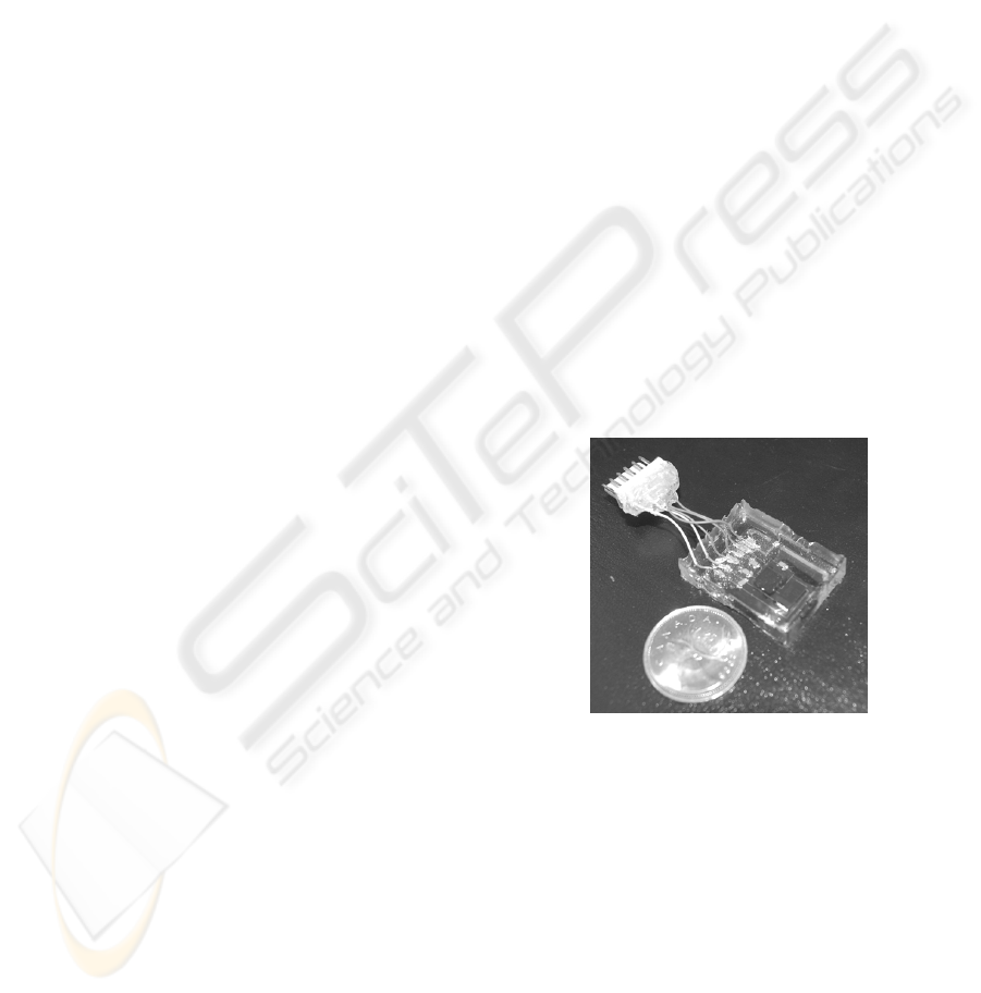
described in the previous section. Figure 6 shows
one of two devices encapsulated in 5mm thick
silicone encapsulant. Although it was 2mm thicker
than the 3mm that was planned, the device was
flexible enough to bend up to 30° without any
visible cracking or detachment between the substrate
and encapsulant.
Figure 6: Encapsulated multisensor layer with macro-scale
connector for testing attached, comparison with a
Canadian quarter.
The remaining two of the four devices were
encapsulated in 0.5mm thick silicone. Figure 7
shows one of the two devices wrapped around a
finger demonstrating its flexibility. With the 0.5mm
encapsulation thickness, although no quite enough to
form a levelled-surface over the larger components,
it was sufficient to provide electric insulation on
most parts and some degree of mechanical
protection. The device was able to bend up to 90°
without any visible cracking or detachment between
the substrate and encapsulant.
MULTIPARAMETER SINGLE LOCUS INTEGRATED MULTILAYER POLYMER MICROSENSOR SYSTEM
39
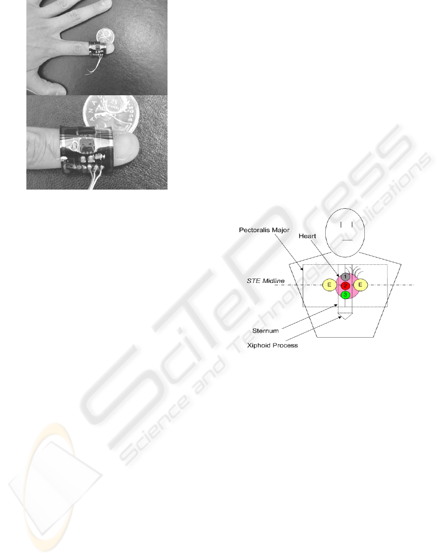
Figure 7: Thin encapsulation of multisensor layer allowing
for extra flexibility; Top, sensor device wrapped around
the first digit of a finger; Bottom, close-up of sensor
wrapped around finger.
5.2 Size and Dimensions
The model multisensor layer devices were
approximately 2.0cmх2.5cm. As can be seen in
Figure 6 and Figure 7, the metal traces were
relatively thick, components were relatively large,
and spacing between components was maintained
such that assembly by hand without any precision
tools can be managed. Should the devices be
populated on the substrate without the manufacturer
packaging, and/or smaller footprints and traces
applied, the device dimensions should be easily
reduced to half the model size, say 1.0cmх1.5cm.
5.3 Comparative Functional
Assessment
Initial comparative function assessment was
conducted to provide quick insight into how the
novel device’s sensing capabilities compared to
traditional devices in the particular application. The
comparative assessment gave an overview of the
device functional performance prior to engaging into
more detailed studies of its performance
characteristics, which will be topic of another
discussion.
In the comparative assessment, the multisensor
was applied in the same manner as traditional
accelerometers on the chest of the subject in
obtaining BCGs (McKay, 1999). Figure 8 shows the
sensor locations and reference electrode locations
for comparative study. Locations 1, 2, 3, show the
various positions the sensors can be placed along the
subject’s sternum in recording heart motion. Ideally,
sensors should be situated simultaneously at the
same location for most accurate comparison, but
such placement is not possible. Differences in signal
outputs due to location were thus considered during
the analysis. Two electrodes, E, approximately 2”
apart were placed beside the sternum along the
sternal midline to form a reference modified-ECG-
lead in studying a subject’s BECG.
At this stage, only the motion sensing element of
the multisensor was compared with other traditional
sensors. It is important to assess first whether or not
the signal pickup by the integrated sensors suffers
any unwanted effects due to the flexible substrate.
For testing purposes, attachment of the sensors to the
subject skin surface was with common off-shelf non-
conducting double-sided medical adhesives.
Figure 8: Sensor placement locations in comparative
assessment; E denotes electrode locations, while 1, 2, 3,
denotes sensor locations.
The data acquisition system and sensor powering is
shown below in Figure 9. The flexible multisensor
was connected with power input, and signal output
routed to filtering and amplification circuits. The
conditioned signals were then passed into a data
acquisition system (National Instruments DAQ)
stored and analysed. Additional sensors included in
the comparison were also digitized and stored
through the same data acquisition system such that
precise synchronization between channels recording
incoming signals can be obtained. The reference
electrodes were connected to a standard ECG
machine (Burdick) with analog output connected to
the acquisition system as the sensors were.
BIODEVICES 2008 - International Conference on Biomedical Electronics and Devices
40
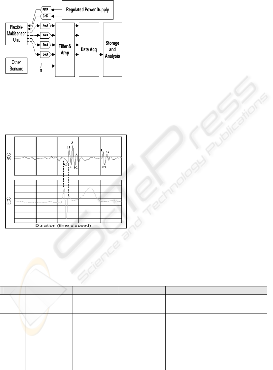
Figure 9: Data acquisition system and sensor connection
setup.
Figure 10 shows the physiological signals of a single
heart-cycle recorded through the acquisition system
of the flexible multisensor with reference to
synchronized ECG.
Figure 10: BCG signal of a single heart-cycle as recorded
by the multisensor referenced to synchronized ECG.
As can be seen, all characteristic waveforms of a
classical BCG signal, denoted by letters (H, I, J,
etc.), similar to that measured through a high-
precision accelerometer in McKay (1999), can be
identified. Several feature extraction algorithms and
physiological interpretation analysis were also
developed; however, such topics were reserved for
subject of a separate discussion.
A total of four comparative recordings were taken
from a single subject. With a high-precision
reference accelerometer (Bruel&Kjaer) fixed at
location-3 (Figure 8), the flexible multisensor and a
rigid sensor, housing the same MEMS 3-axis
accelerometer on PCB, were rotated between
location-1 and location-2. Samples were taken for
duration of 30-seconds at 500Hz (each channel) over
a total of four channels (3 sensors, 1 reference ECG-
lead). Table
1 summarizes the recordings and the
different sensor placements during each trial. From
the combination of trials recorded and reference
sensor comparison, the quality of signal related to
sensor placement, and filtering differences can be
qualitatively assessed.
Figure 11 shows a portion of the recorded signals
from trial-I over a period of 2.6-seconds, or
approximately three heart-beats. Channel-1 shows
signal recorded from the rigid sensor, while channel-
2 shows signal recorded from the flexible
multisensor. Channel-3 and Channel-4 form the
reference BCG and ECG signals respectively, in
which the flexible sensor and rigid sensor were
compared to. Although the sensitivities of the
MEMS accelerometer is much lower than the high-
precision reference accelerometer, it was
qualitatively determined, that in general, the
morphology of the BCG signals obtained from the
flexible multisensor is very similar to that in the
reference sensor.
Table 1: Summary of sensor recordings with location, filter, and overall sensitivity-gain indicated.
Trail Sensor Location Filter Overall Sensitivity/Gain (approx.)
I Rigid 1 50Hz 3.0V/g
Flex 2 100Hz 3.0V/g
Reference 3 100Hz 9.8V/g
II Rigid 2 50Hz 3.0V/g
Flex 1 100Hz 3.0V/g
Reference 3 100Hz 9.8V/g
III Rigid 1 100Hz 3.0V/g
Flex 2 50Hz 3.0V/g
Reference 3 100Hz 9.8V/g
IV Rigid 2 100Hz 3.0V/g
Flex 1 50Hz 3.0V/g
Reference 3 100Hz 9.8V/g
MULTIPARAMETER SINGLE LOCUS INTEGRATED MULTILAYER POLYMER MICROSENSOR SYSTEM
41
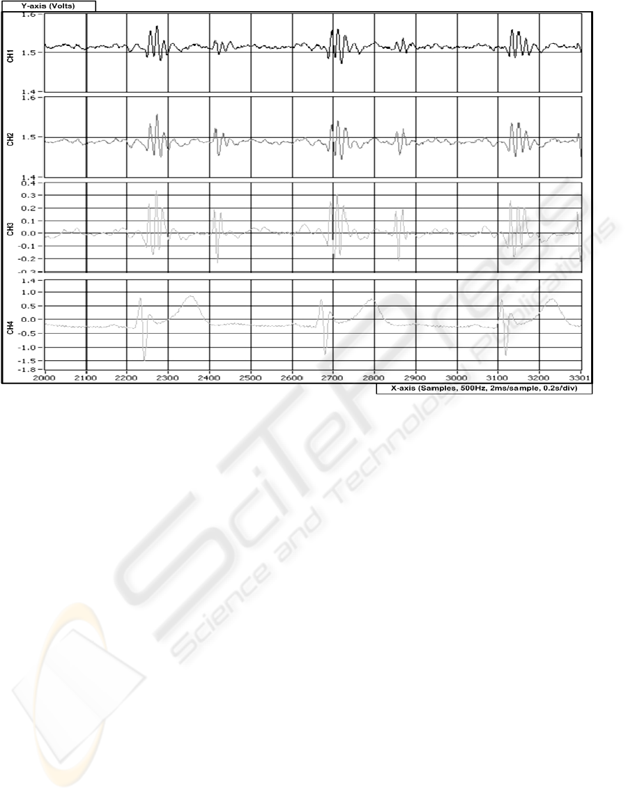
Figure 11: Portion of recording comparing novel flexible multisensor with rigid sensor and reference sensor and ECG; CH1
– rigid sensor; CH2 – flexible multisensor; CH3 – high-precision accelerometer reference; CH4 – ECG. All channels
sampled at 500Hz.
Further, from trials-I and III, it was observed that
altering the filtering cut-off frequencies in the signal
conditioning stage did not have astonishing effects
on the morphology of the signals as expected. On
the other hand, situating sensors further away from
the reference sensor did result in signals less similar
in morphology and smaller amplitude compared to
sensors closer to the reference sensor. That is to say,
regardless of sensor type (rigid or flexible) and
filtering cut-off frequency, a sensor placed at
location-2 provided signals closer than a sensor
placed at location-1 when compared to the reference
at location-3. Nevertheless, the filtering and location
effects observed should be subject for a more
controlled study in the future.
From the qualitative comparative observations
gathered, it can be concluded that first, the novel
flexible multisensor provided similar functional
sensitivity as the rigid PCB version housing the
same 3-axis MEMS accelerometer. This was a
preliminary indicator that suggested that the flexible
substrate proposed in the multiparameter single
locus multilayer integrated microsenor system does
not inhibit the actuation-sensor coupling due to its
flexibility. Next, the signals recorded from the
flexible multisensor were essentially similar in
morphology as the high-precision reference
accelerometer. This is an indicator that the novel
flexible multisensor has potential for applications in
BECG with medical diagnostic grade precision,
while providing a highly-integrated system in the
near future.
6 CONCLUSIONS
State-of-the-art technologies in microintegrated
multisensor systems were discussed. It was noted
that the current systems lacked several important
modules and features useful in certain specialized
healthcare monitoring and medical diagnostic
applications. A mutliparameter single locus
integrated multilayer polymer microsensor system
was proposed to incorporate high-density
multisensor and microelectronics system integration
on a flexible substrate platform that provides good
skin conformity in physiological applications.
Architecture of the proposed system was discussed,
as well as the implementation and fabrication of the
multisensor layer of the multilayer system. Model
BIODEVICES 2008 - International Conference on Biomedical Electronics and Devices
42

devices of the multisensor layer were shown and
their mechanical characteristics discussed,
particularly, it demonstrated excellent flexibility for
good skin conformity. It was also demonstrated that
information on bodily motion due to cardiac
contraction, or BCG signals, can be acquired
through sensors integrated on the proposed platform.
The system further shows potential for medical
grade diagnostic performance. Further testing and
characterization of more compact and highly-
integrated models of the proposed system is under
development, and will ultimately provide more
insightful understanding of the effectiveness of the
proposed microintegration platform.
ACKNOWLEDGEMENTS
The authors would like to thank Jasbir Patel from the
Computational Integrative BioEngineering Research
Lab and Microfluidics Lab at Simon Fraser
University for his help on silicone microfabrication.
The authors would also like to thank See-Ho Tsang
from the Institute for Micromachining and
Microfabrication Research at Simon Fraser
University for his help on polyimide circuit
fabrication. Further, the authors would like to
acknowledge CMC Microsystems for their ongoing
support in hybrid micro integration and device
fabrication assistance.
REFERENCES
Wang, L., Tang, T.B., Johannessen, E., Astaras, A.,2002.
An Integrated Sensor Microsystem for Industrial and
Biomedical Applications. IEEE Instrument and
Measurement, [online]. Available from:
http://www.see.ed.ac.uk/~aa/WanTanJohAst02b.pdf
[cited 18 June 2007].
Richards Grayson, A., Shawgo, R., Johnson, A., Flynn, N.,
Li, Y., Cima, M., Langer, R., 2004. A BioMEMS
Review: MEMS Technology for Physiologically
Integrated Devices. Proceedings of the IEEE, [online].
92 (1), pp 6-20.
Kundert, K., Chang, H., Jefferies, D., Lamant, G.,
Malavasi, E., Sendig,F., 2000. Design of Mixed-Signal
Systems-on-a-chip. IEEE Transaction on Computer
Aided Design of Integrated Circuits and Systems. 19
(12), pp 1561-1571.
Matthews, D. J., Gaynor, M. P., 2003. RF System in
Package: Considerations, Technologies and Solutions.
Amkor Technologies. [online]. Available from:
www.amkor.com/products/notes_papers/RF_SiP_Pape
r041403.pdf, [cited 18 June 2007]
Advanced Assembly and Packaging for Biomedical
Devices. Fraunhofer Institut Zuverlassigkeit und
Mikrointegration. [online].Available from:
http://www.pb.izm.fhg.de/izm/040_Publi_News/index.
html, [cited 18 June 2007]
Pai, R., Roussel, T., Crain, M., Jackson, D., Conklin, J.,
Baldwin, R., Keynton, R., Naber, J., Walsh, K., 2001.
Integrated Electrochemical Detection for Lab on a
Chip Analytical Microsystems. Proceedings of the
Fourteenth Biennial University/Government/Industry
Micro electronics Symposium. pp 167-170.
Zhang, J., Manson, A., 2007. Highly Adaptive Transducer
Interface Circuit for Multiparameter Microsystems.
IEEE Transactions on Circuits and Systems. 54 (1), pp
167-177.
Callister, 2003. Materials Science and Engineering and
Introduction 6
th
ed., Wiley & Sons, USA.
Egloff, E. R., The Art of Design and Manufacture of
Polymer Thick Film Circuits. Screen Printing and
Graphic Imaging Association International Technical
Guidebook. [online]. Available from:
www.sgia.org/pdf_server.cfm?pdf=/members/tgbArch
ive/2028.pdf, [cited 19 June 2007].
McKay, W., Gregson, P., McKay, B., Militzer, J., 1999.
Sternal Acceleration Ballistocardiography and Arterial
Pressure Wave Analysis to Determine Stroke Volume.
Clin Invest Med. 2 (1), pp 4-14.
MULTIPARAMETER SINGLE LOCUS INTEGRATED MULTILAYER POLYMER MICROSENSOR SYSTEM
43
