
OUT OF CORE CONSTRUCTION OF PATCH TREES
Hermann Birkholz
Institute for Informatics, University of Rostock, Albert-Einstein Street 21, 18059 Rostock, Germany
Keywords: Out of Core, Patch Tree, Level of Detail.
Abstract: Current Level of Detail (LoD) approaches for triangle meshes use variably triangulated mesh patches in
order to approximate the original mesh surface. The approximation is synthesized from some of these
patches, which have to cover the whole surface and must not intersect each other. The patches are chosen
corresponding to the necessary view dependent triangulation. This paper addresses the creation of the re-
quired hierarchical data structures, in order to enable Level of Detail synthesis for very large triangle
meshes. Because of the limited amount of internal memory, most of the mesh data reside in external mem-
ory during the process. Due to the high access latency of external memory, commonly used algorithms for
small meshes are hardly applicable for so called “Out of Core” meshes. Other methods have to be found that
overcome the problems with the external memory.
1 INTRODUCTION
Widely available massive triangle meshes that are
for instance results of highly detailed laser scans,
demand special algorithms in order to explore them
interactively.
Due to its size the complete data set does not fit
into the internal memory of current PC hardware.
Thus, only parts of the mesh can be used for a real-
time exploration, while most of the data have to re-
main in external memory. This demands fast swaps
between external and internal memory.
Thus, interactive Level of Detail (LoD) algo-
rithms use mesh patches, in order to synthesize ap-
proximations of the original mesh. These mesh
patches have different levels of detail and can be
merged into a mesh which covers the complete sur-
face of the original mesh.
This paper describes the creation of the neces-
sary data structures for a patch-based LoD algorithm
in external memory. Due to the speed limitations of
external memory devices, the process is serialized as
much as possible and uses efficient caching.
First, a short selection of related articles is given
in the next section. The third section describes the
usage and the creation of so called “patch trees”,
which enable a patch based LoD synthesis. Finally
some results an a short conclusion are given in the
following sections.
2 RELATED WORK
Popular LoD schemas, such as “edge collapse”-
hierarchies for arbitrary meshes (Hoppe, 1997) or
ROAM for height-field meshes (Duchaineau, 2001)
are normally used with small data sets and have a
very fine granularity. For these examples, the granu-
larity for LoD operations is two triangles and creates
a high CPU load during mesh updates. Furthermore,
memory swap operations are very inefficient for
such a fine granularity, because external memory
operations are only efficient for larger blocks of
memory and sequential access.
In (Hoppe, 1998) an “Out-of-Core” terrain ren-
dering system is presented, that creates a Progressive
Mesh in external memory. Therefore the terrain map
is divided into blocks, which are independently sim-
plified (borders must not be changed). After that,
these blocks are merged and simplified again, until
only one block remains. The externally stored “edge
collapse”-hierarchy is used to approximate the origi-
nal terrain data set.
Newer approaches (Cignoni, 2003, 2004, 2005)
use mesh patches to assemble the mesh approxima-
tion. The first approach uses the ROAM hierarchy
together with a batched height-field mesh, while the
second approach can also be used for arbitrary
meshes. The third approach generalizes the MT-
hierarchy (Puppo, 1996) data structure for the use
with patches. The patches in these approaches con-
tain many triangles and thereby increase the granu-
153
Birkholz H. (2007).
OUT OF CORE CONSTRUCTION OF PATCH TREES.
In Proceedings of the Second International Conference on Computer Graphics Theory and Applications - GM/R, pages 153-158
DOI: 10.5220/0002081801530158
Copyright
c
SciTePress
larity of the LoD algorithm. This also reduces the
necessary hierarchy structure that stores how patches
can be substituted. Such smaller hierarchy structures
furthermore reduce the CPU-load during mesh up-
dates.
3 PATCH TREES
A patch tree is a data structure that describes the
surface of a triangle mesh with different levels of
detail. All nodes of the tree contain compact mesh
patches, which are used to synthesize view depend-
ent approximations of the original mesh. The leaf
nodes contain the original geometry of the mesh,
while parent nodes always contain a simplified ver-
sion of the geometry of their child nodes.
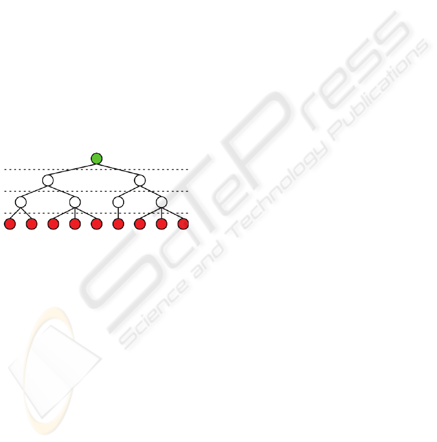
In the context of this paper, the tree is con-
structed with a number of levels that all cover the
complete mesh surface. This means that all leaves of
the tree share the same level and the path length of
all leaf nodes to the root is equal. Figure 1 shows an
example of a typical patch tree.
Figure 1: Simple patch tree structure.
Such patch trees can be used to create approxima-
tions of the original mesh with a restricted cut across
the tree. The cut is constrained to prevent adjacent
patches in the approximation that are more than one
level apart. This constraint enables the pre-
computation of the transitions between adjacent
patches in different levels of the tree.
3.1 Out of Core Creation
The creation of patch trees for very large triangle
meshes, which do not fit into the internal memory, is
very challenging. Due to the evenly distributed ac-
cesses to the surface during the construction of a
patch tree, a direct adoption of standard algorithms
is hardly applicable. Both, the greedy construction of
patches and the surface simplification demand ran-
dom access to the surface data. Due to the high ac-
cess latency of the external memory, most of the
process time would be spent waiting for the external
memory feedback.
In order to reduce the negative effect of external
memory access, intelligent methods have to be used
to reduce random accesses to the surface.
One very important tool to achieve this is the
external heap. This heap enables to serialize many
accesses to external memory by a fast and latency-
optimized sorting of items in the external memory.
Further optimizations can be reached by minimizing
the random accesses to the external memory with
intelligent caching.
The process queue, which is used to create the
patch tree consists of three steps:
Create leaf patches
Straighten borders of leaf patches
Create patch hierarchy
These steps will be further described now.
3.1.1 Create Leaf Patches
In this step, the triangle mesh (indexed mesh) is
segmented into patches. Therefore an average num-
ber of triangles per patch is chosen (e.g. 1000 trian-
gle/patch) and used to determine the number of leaf
patches.
During the creation of the desired number of
patches from the original triangles, all triangles are
treated as patches. First the neighbor-patches of all
triangular patches are determined. Because the mesh
does not fit into internal memory, the process is seri-
alized with external heaps. Therefore all patches are
brought to an external heap, weighted with each of
their vertex indices in ascending order. Now the
patches are read back from the heap, grouped by
equal vertex indices. The neighborhood in each
group is found according to the common vertex in-
dex. After the neighbor has been set, the resulting
triangle is brought to another heap, weighted with
the original triangle index. Now the triangles are
read back from the second heap. Three items are
read from the heap at a time that belong to the same
triangular patch and contain the neighbors. During
the same process, the vertex positions can be associ-
ated with each patch, in order to determine its area
and border segment lengths.
The merge process, which iteratively merges the
two best possible patches into a new patch, cannot
be serialized in the way seen before. Thus the ran-
dom accesses have to be reduced by intelligent cach-
ing. The priority of the merge operations is deter-
mined by the compactness of their results. Each
patch is tested with all adjacent patches and the best
result is chosen as merge-target. The compactness is
measured as circle similarity. The area and the out-
line of the resulting patch is known and thus the
similarity to a circle can be computed. In this ap-
proach, the following measure is used:
GRAPP 2007 - International Conference on Computer Graphics Theory and Applications
154
2
*4
2
areaoutline
priority
π
+
=
(1)
This measure prefers short outlines such as in
(Sanders, 2001) but also prevents large areas with
small outlines, which could occur on separated fea-
tures such as legs or arms.
The caching is realized with an octree, in order
to make use of spatial coherence. The merge algo-
rithm reads an octree node and merges all patch-
pairs whose priority is locally minimal. When no
further merges are possible in the internal memory
part, this region is extended around the octree-node
in internal memory that contains the lowest merge
priority. There will always be patches (border
patches), whose adjacent patches still reside in ex-
ternal memory and thus prevent the computation of a
merge priority. Patches adjacent to border patches
cannot be used for merging, because it is impossible
to determine whether their priorities are locally
minimal. Thus there will always remain patches with
low priorities in internal memory, which can be used
to extend the internal memory footprint until all re-
maining patches reside in internal memory.
This process continues until no further, locally
minimal merge operations are possible. When the
internal memory usage exceeds a given threshold,
parts of the internal memory are written back to the
octree. During the merge process, the indices of the
two merged patches and of their parent patch are
stored into an external heap, weighted with their
compactness measure (descending). When the com-
pactness value of one of the child patches is higher
than the one of the resulting patch, the highest com-
pactness measure is associated with the heap item.
This enables refining the resulting binary hierarchy
of patches by simply removing items from the heap.
After a number of items was removed from the heap,
the leaf patches and their binary subtree can be col-
lected from the heap. The leaf nodes of the subtrees
contain the associated triangles of the patch.
3.1.2 Straighten Patch Borders
The leaf patches, which were generated in the last
paragraph, have relatively rough borders. To im-
prove the synthesis of approximations, the borders
should be smoothed. Figure 2 shows a the difference
between the initial rough borders and the straight-
ened borders. It is visible that the general shape was
preserved in the smoothing process, while many
small corners were smoothed.
Figure 2: Straightened patch borders.
To straighten the borders of the patches, the path
length has to be shortened between two sequenced
patch corners. The shape of the patches is preserved
with the use of local shorten-operations only. Only
vertices in the direct neighborhood of the path (1-
neighborhood) can be used in the optimization. Due
to the large amount of data that has to be processed,
this process is serialized again.
The optimization heap is constructed from the
triangles of the surface. The triangles are first sorted
by their patch index with another heap. This enables
to collect the triangles per patch. Then each triangle
is brought to the optimization heap. The triangles are
weighted corresponding to the data associated with
the patch. If all adjacent patches have higher indices,
the patch index of the triangle is chosen. Otherwise
the lowest index of the adjacent patches is chosen.
This ensures that each triangle occurs only once in
the optimization heap. After the optimization heap is
initialized, all triangles with the same priority are
read from the heap into the internal memory. In in-
ternal memory the optimization for the available
borders between the patches can be computed, by
iteratively shortening the border path in the local
neighborhood. Only the 1-neighborhood (1 vertex
distance to the previous path) is considered during
the optimization. After that, the resulting triangles
are written back to external memory. If the triangle
is associated with a patch whose adjacent patches
have all higher indices than the current priority, this
triangle is written to the result heap and weighted
with its associated patch index. Otherwise the trian-
gle is brought back to the optimization heap,
weighted with the lowest index among the associ-
ated patch and its direct neighbors that is greater
than the current priority. This process is repeated
until all triangles are situated in the result heap.
OUT OF CORE CONSTRUCTION OF PATCH TREES
155
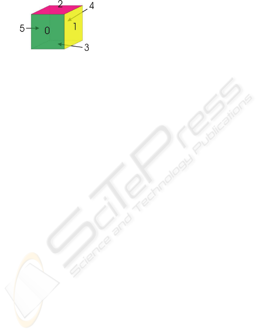
Figure 3: Example patches.
Figure 3 shows an example for this process. The
surface is divided into six patches and all patch bor-
ders have to be tested for optimizations. First the
optimization heap is initialized with all triangles of
the six patches. In this example
w
p
T
describes the set
of triangles that belongs to patch p and has the prior-
ity w. The initial heap now looks like this:
0
0
T ,
0
1
T ,
0
2
T ,
0
3
T ,
0
5
T ,
1
4
T
First the triangles with the priority 0 are read
from the heap. The borders between the patches 0
and its neighbors 1, 2, 3, 5 are tightened. After that,
all triangles of patch 0 are written to the result heap,
because all border segments have been processed.
All other triangles are written back to the optimiza-
tion heap, weighted with the next larger patch index
among the neighbor patches. This results in the fol-
lowing sequence:
1
1
T ,
1
2
T ,
1
3
T
,
1
4
T ,
2
5
T
Now all triangles with a priority of 1 are read
from the optimization heap. The border segments
between patch 1 and patches 2, 3 and 4 are
smoothed. The border between patch 1 and patch 0
has already been smoothed, when patch 0 was proc-
essed. After that, the triangles of patch 1 are brought
to the result heap while the other triangles are writ-
ten back to the optimization heap, weighted with the
next patch index in their neighborhood. This results
in the optimization heap:
2
2
T ,
2
4
T ,
2
5
T ,
3
3
T
The optimization continues, until all triangles are
brought to the result heap. Then all triangles can be
collected from the result heap, according to their
final patch index.
3.1.3 Create Patch Hierarchy
In this last step, the final patch tree is created from
the given leaf patches. This includes the creation of
new patch levels together with geometric simplifica-
tions of the surface. The geometry is simplified with
iterative half-edge collapse (Kobbelt, 1996) opera-
tions. The sequence of collapses is controlled by the
QEM (Garland, 1996).
The patch tree structure should completely fit
into the internal memory now. Thus, all further
merge operations are executed without access to
external memory. The triangle data of the patches
however, does not fit into the internal memory and
has to remain in external memory. Thus, the process
of surface simplification has to be optimized for
external memory as well.
Before the process starts, initial QEM matrices
are computed for each vertex. This can easily be
serialized with external heaps again. After that, the
new patch level is created by halving the number of
current patches. Now the number of triangles has to
be halved from the current patch level to the new
patch level. Therefore all triangles and vertices of
the current level are written to a temporary file, as-
sociated with their new patch index. Now the ge-
ometry data of each patch can be read as one block
from external memory.
The geometric simplification is similar to the
creation of the initial patches in the beginning. First,
an arbitrary patch is read from the external memory
to the internal memory. Then the vertices in internal
memory are classified into border, near-border and
inner vertices. The border vertices have the property
that at least one direct neighbor is not yet in the in-
ternal memory. The near-border vertices must have
at least one border vertex in their neighborhood,
while inner vertices have only other inner or near-
border vertices in their neighborhood. Thus, col-
lapse targets can be found for near-border and inner
vertices only, while locally minimal collapse opera-
tions can be found among inner vertices only.
After the patch geometry is read and classified,
all possible locally minimal collapse operations are
performed. For each collapse operation, the indices
of both collapsed vertices are brought to an external
heap (descending), weighted with their collapse er-
ror. If one of the collapsed vertices had a higher
QEM error, this error is used as heap priority. Then
the near-border vertex with the least QEM error is
chosen, in order to expand the region in the internal
memory around the associated patches (vertices can
be shared by multiple patches). The geometry of the
new patches is read from external memory and clas-
sified. This includes an update of some vertices,
which already reside in internal memory, because
their border/near-border status could have changed.
Again, all locally minimal collapse operations are
performed and the region in the internal memory is
expanded. This process is repeated, until no further
expansion is possible. Whenever the amount of used
internal memory exceeds a given threshold, the ge-
GRAPP 2007 - International Conference on Computer Graphics Theory and Applications
156
ometry of patches with the highest near-border
QEM errors, is moved back to external memory.
After the process has finished, all patches have
to be checked whether they contain inner vertices or
not. If inner vertices remained, the process has to be
started again with one of these patches. Such non-
processed inner vertices can occur under some cir-
cumstances, when a region is surrounded by com-
pletely processed patches and is then written to ex-
ternal memory.
After the simplification, we get a heap that con-
tains a sequence of collapse operations and thus the
simplification hierarchy. To extract the geometry for
the new patch tree level, the result vertices have to
be refined. This is done by removing the first items
from the heap, until the correct number of triangles
is reached. Now the geometry is adopted to the re-
fined vertices and stored according to the patches in
the new patch level.
The creation of new patch levels and the simpli-
fication of the geometry are repeated, until the num-
ber of patches reaches a given threshold. The result
is a patch tree, with a structure like the one in the
first figure. All leaf nodes are situated in the same
level and have a parent node in the next level, except
for the root node.
3.2 LoD Synthesis
Once the patch tree has been created, it can be used
to assemble approximations of the original mesh. To
measure the effect of an patch refinement in the ap-
proximation, object space errors have to be com-
puted. Therefore all child patches are recursively
projected to their parent patches. Now the average
squared distance of all vertices to their projection is
computed. The projection is computed by locking
the common vertices in both levels and by placing
the other vertices according to their locked
neighbors. The placement is determined with the
mean value coordinates (Floater, 2001). After the
vertices of the child patches have been projected to
their parent patch, the average squared distance to
their original position is computed. Furthermore, the
center and radius of a bounding sphere for each
patch is computed to enable view frustum culling.
For a view-dependent approximation a priority
queue (descending) is initialized with the root
patches. The object space error of each queued patch
is computed by dividing the average squared dis-
tance of the patch with the squared distance to the
viewer. Furthermore, a view frustum test is per-
formed for each patch, to determine whether it is
visible. Invisible patches are marked and assigned to
a view dependent error value of zero.
During the refinement, the first item is iteratively
read from the priority queue and used for refine-
ment. The refinement step is constrained to allow
only patch splits, if the parent patches of its neighbor
patches (in the same patch level) have already been
split. If not, these parent patches are split before the
current patch (forced split). This ensures a maximum
level difference of 1 between adjacent patches in the
final approximation.
Before the approximation is sent to the GPU, all
transitions between patches of different levels have
to be created. Due to the constrained possible transi-
tions, all states of triangles in the transition area can
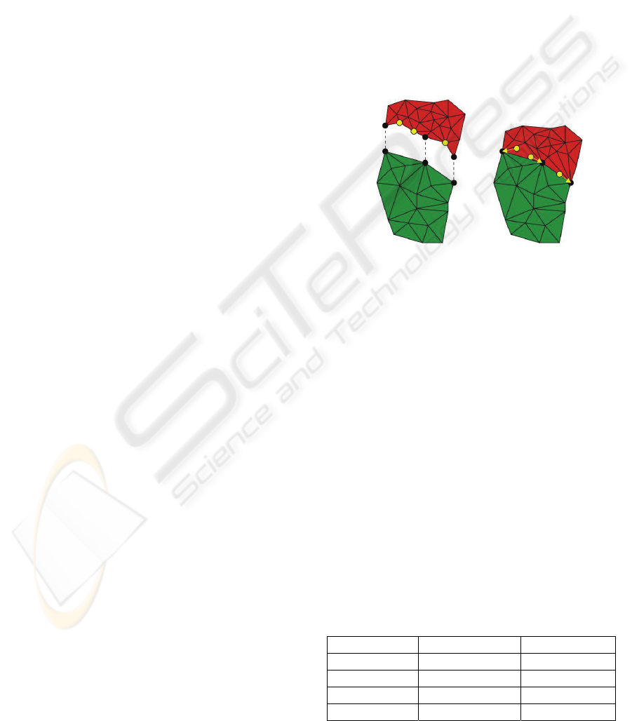
be computed in an offline process. Figure 4 shows
how a border segment of a higher level patch is
adopted to a lower level patch.
Figure 4: Patch transition.
The changes in the geometry due to the level
transition introduce new surface errors in the ap-
proximated surface, but these errors occur only at
borders to coarser detail-levels which have an higher
approximation error anyway.
The reference to all vertices in the high level
patch, which do not occur in the low level patch, are
moved to the nearest common vertex on the border
segment. Finally the geometry of all patches can be
sent to the GPU.
4 RESULTS
The patch tree construction process has been imple-
mented and tested with different meshes. Due to the
early prototype status of the software, only water-
tight meshes (no holes in the surface) can be proc-
essed for now. Table 1 lists four test meshes.
Table 1: Test meshes.
Name Triangles Vertices
Armadillo 345,944 172,974
Artificial 1 8,388,608 4,194,306
Artificial 2 33,554,432 16,777,218
Artificial 3 134,217,728 67,108,866
OUT OF CORE CONSTRUCTION OF PATCH TREES
157
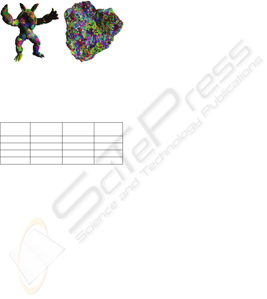
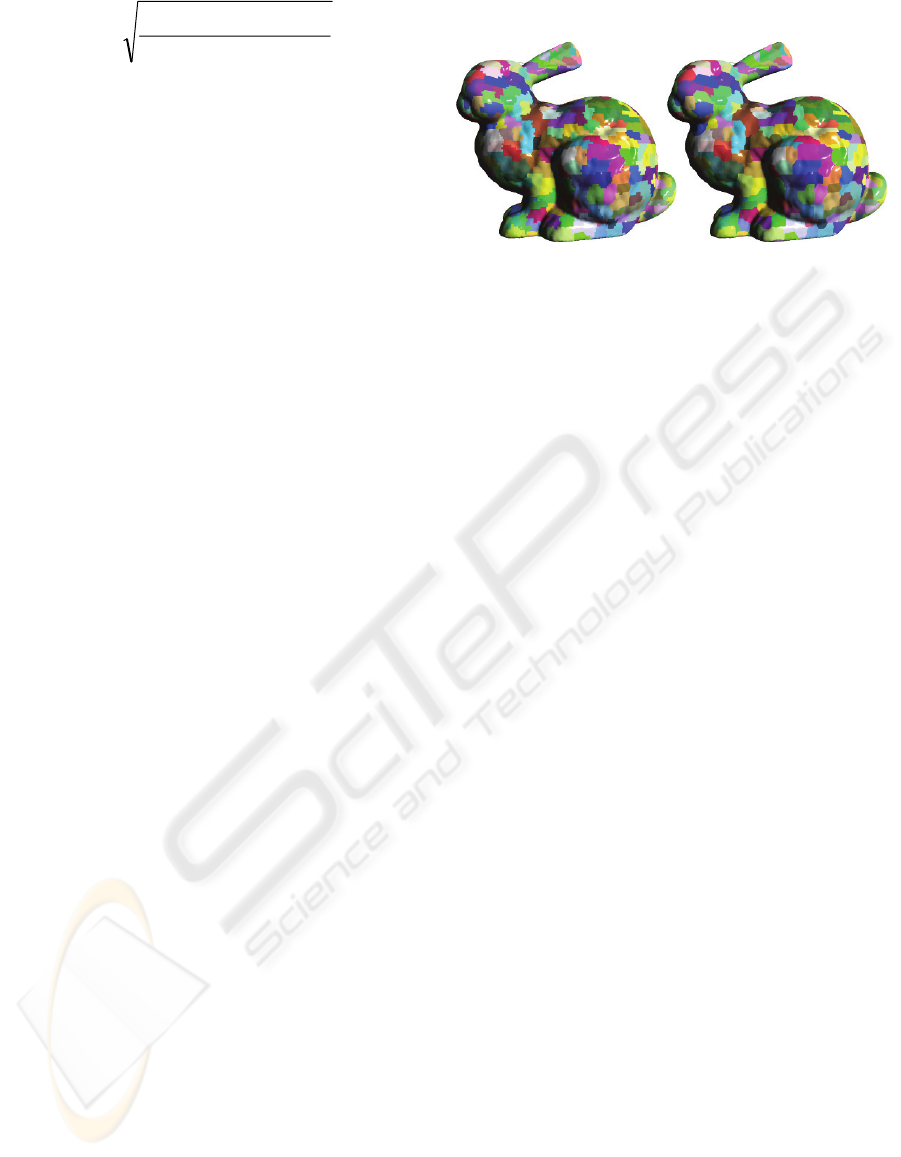
Due to the lack of large watertight meshes the
last three meshes were computed with a fractal sub-
division method on a sphere surface. There are only
differences in the details structure. Figure 5 shows
the leaf patches of the first two meshes.
Figure 5: Leaf patches of first two test meshes.
The results of the patch tree construction process
can be read on table 2. Patch trees with average
patch sizes of 1,000 triangles have been built for all
test meshes.
Table 2: Patch tree results.
Name Leaf
Patches
Tighten
Borders
Final Hi-
erarchy
Armadillo 71 s 46 s 102 s
Artificial 1 3,495 s 2,145 s 4,833 s
Artificial 2 10,089 s 6,391 s 16,408 s
Artificial 3 45,228 s 29,810 s 71,547 s
The first two meshes have been tested on a 2
GHz Pentium 4 machine with 1 GB of RAM and a
SCSI hard disc. Due to its minor size, the “Arma-
dillo” mesh was processed very fast. Almost all ex-
ternal memory operations have been cached by the
operating system. The last two meshes have been
processed with an Athlon64 3800+ with 4 GB of
RAM and a SATA hard disc. The size of the usable
memory (except for the final patch hierarchy struc-
ture) was set to 150 MB. The results still show a
relatively long processing time for the large meshes.
However, basic simplification algorithms that do not
care about spatial coherence or serialization, would
spend even weeks to process such large data-sets.
Moreover there is enough room for further speedups.
Especially a less primitive version of the external
heap would be very helpful.
The resulting patch hierarchies can be used for
interactive exploration of the corresponding triangle
meshes. The low complexity of the patch trees re-
duces the CPU load and thus enable better usage of
the GPU bandwidth. Surely the data should be fur-
ther processed. First the sequence of patch-data in
external memory can be improved by grouping se-
mantically near parts of the tree together. Further-
more the amount of data for the patches can be re-
duced by striping. And if a number of vertices below
65,536 can be guaranteed for each patch, the indices
can be stored with 16 bits instead of 32.
5 CONCLUSIONS
In this paper an process queue has been presented
which automatically generates patch trees from large
triangle meshes. A two day processing time for a
128M triangle mesh is not bad but improvable.
REFERENCES
Cignoni, P., Ganovelli, F., Gobbetti, E., Marton, F.,
Ponchio, F., Scopino, R., 2003. Batched dynamic
adaptive meshes for high performance terrain visuali-
zation., Computer Graphics Forum
Cignoni, P., Ganovelli, F., Gobbetti, E., Marton, F., Pon-
chio, F., Scopino, R., 2004, Adaptive tetrapuzzles: ef-
ficient out-of-core construction and visualization of
gigantic multiresolution polygonal models. ACM
Trans. Graph.
Cignoni, P., Ganovelli, F., Gobbetti, E., Marton, F.,
Ponchio, F., Scopino, R., 2005, Batched Multi
Triangulation, Proceedings IEEE Visualization.
Duchaineau, M.A., Wolinsky, M., Sigeti, D.E., Miller,
M.C., Aldrich, C., Mineev-Weinstein, M.B., 1997,
ROAMing terrain: Real-time optimally adapting
meshes, Proceedings IEEE Visualization
Floater, M.S., 2003, Mean value coordinates, Computer
Aided Geometric Design
Garland, M., Heckbert, P.S., 1997, Surface Simplification
Using Quadric Error Metrics, SIGGRAPH ’97 Con-
ference Proceedings
Hoppe, H., 1997, View Dependent Refinement of Progres-
sive Meshes, Computer Graphics
Kobbelt, L., Campagna, S., Vorsatz, J., Seidel, H.-P.,
1998, Interactive multi-resolution modeling on arbi-
trary meshes, Proceedings of the 25th annual confer-
ence on Computer graphics and interactive techniques
Puppo, E., 1996, Variable Resolution terrain surfaces,
Proc. Of 8
th
Canadian Conference of Computational
Geometry
Sander, P.V., Snyder, J., Gortler, S.J., Hoppe, H., 2001,
Texture Mapping Progressive Meshes, Computer
Graphics Proceedings, ACM Press
GRAPP 2007 - International Conference on Computer Graphics Theory and Applications
158
