BUILDING 3D INDOOR SCENES TOPOLOGY FROM
2D ARCHITECTURAL PLANS
Sebastien Horna, Guillaume Damiand, Daniel Meneveaux and Yves Bertrand
SIC laboratory, University of Poitiers, France
Keywords:
3D modelling, architectural scenes, reconstruction, topological model.
Abstract:
This paper presents a new method for reconstructing geometry and topology of 3D buildings from 2D ar-
chitectural plans. A complete topological model expresses incidence and adjacency relations between all the
elements. It is necessary for both recovering accurately 2D information and constructing a coherent 3D build-
ing. Based on an existing topological kernel, several high-level operations have been developped in 2D for
creating walls, portals, stairs, etc. Semantic information is associated with all volumes for specifying open-
ings, walls, rooms, stairs, facade, etc. The resulting 2D model is extruded for generating a 3D environment,
taking the semantic information into account since doors are not processed as walls for instance. Floors are
superimposed using volumes corresponding to upper and lower ceilings linked according to stairways. The
resulting models are suitable for various application such as walkthrough, lighting/wave propoagation/thermal
simulation.
1 INTRODUCTION
Accurate three dimensional descriptions of architec-
tural environments is an important need for many
building trades such as lighting engineering, thermal
simulations, etc. Generally, the models produced by
the architects are handled in two dimensions with-
out any topological information. However, in addi-
tion to a three dimensional description of the model,
many simulation algorithms require adjacency and in-
cidence relationships between volumes.
Unfortunately, manually reconstructing complex
architectural scenes using a 3D modeller is a long
and tedious process. This is why we propose a new
method for automatically reconstructing 3D buildings
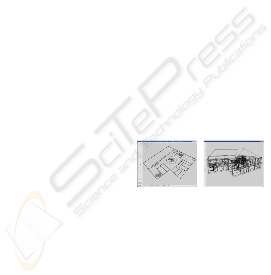
from 2D architectural plans (figure 1). Our method in-
herently integrates a complete topological description
of the environment. The resulting scenes can thus be
edited in a topological modeller for adding furniture,
moving walls, etc. In addition, semantic information
is used for defining object attributes such as rooms,
floor, corridors and so on.
Our aim is to define a building model correspond-
ing to a 3D partition of space. Each room should cor-
Figure 1: 2D plan and 3D reconstruction.
respond to a closed and orientable volume, incident
to closed and orientable faces. Amongst the existing
topological models, we have chosen generalized maps
which allow to represent space subdivisions and inci-
dence and adjacency relations.
The reconstruction method we propose is based
on four main phases: (i) 2D edges processing for
removing geometrical inconsistencies, (ii) topologi-
cal reconstruction with semantic information, (iii) 3D
building extrusion (iv) superimposing of floors. Dur-
ing the first phase, most 2D imprecisions (90%) are
automatically corrected. However, remaining awk-
ward elements can be semi-automatically processed.
Semantic information can be deduced from the plans
37
Horna S., Damiand G., Meneveaux D. and Bertrand Y. (2007).
BUILDING 3D INDOOR SCENES TOPOLOGY FROM 2D ARCHITECTURAL PLANS.
In Proceedings of the Second International Conference on Computer Graphics Theory and Applications - GM/R, pages 37-44
DOI: 10.5220/0002076700370044
Copyright
c
SciTePress
when they exist, or defined manually by the user. The
extrusion operation is guided by the semantics. For
instance, walls, doors or stairs are extruded using spe-
cific rules. Superimposing of floors is applied using
semantics and topology.
The resulting topological indoor models have
been designed so that volumes adjacency can be ef-
ficiently used for various types of simulation. For in-
stance such models prove efficient in the context of
radiosity or photon mapping approaches (Meneveaux
et al., 1998a; Fradin et al., 2005).
This paper is organized as follows. Section 2
describes the existing methods for 3D architectural
scenes construction. Section 3 justifies our choice of
generalized maps. Section 4 presents our method of
geometrical and topological rebuilding in two dimen-
sions. Section 5 details the extrusion and superimpos-
ing of several floors. Section 6 discusses the results
obtained with several examples of real buildings.
2 RELATED WORK
Many methods in the literature propose to rebuild ur-
ban environments. For instance, the MATIS team
in the research section of the French Institut Ge-
ographique National (IGN) proposes an elevation
method starting from satellite photographs (Fuchs
et al., 2003). Ah-Soon et al. processes digitized 2D
drawings (i.e. images of plans) for 3D reconstruc-
tion (Ah-Soon, 1998). Recognition is based on the
detection of vertical and horizontal symbols. The
aim is to analyze the interior geometry of a build-
ing as well as the openings location (doors, windows,
etc). This work primarily concerns methods of image
analysis. The geometry reconstruction produces 3D
scenes without topological information.
Several methods aim at extracting topological in-
formation from a list of polygons, making it possi-
ble to reduce calculations of visibility for lighting
simulation and visualization. Airey et al. propose
a method of binary space subdivision (Binary Space
Partitioning or BSP) for axis-aligned environments
(Airey et al., 1990). Teller et al. present an extension
of this method for all types of walls (Teller, 1992).
Meneveaux et al. propose a method containing rules
to find the parts of the buildings (Meneveaux et al.,
1998b). All these subdivision schemes produce a set
of regions called cells, separated by openings. The
topological description corresponds to adjacency rela-
tions between 3D cells, there no incidence/adjacency
relations between lower-dimensions elements.
Complex urban scenes can also be produced us-
ing procedural modeling, such as cityEngine (Parish
and Muller, 2001; Muller et al., 2006). Several pa-
rameters can be taken into account: population den-
sity or height maps. The road network is generated
using a L-System mechanism. A construction gram-
mar is used to create the building facade. Although
these methods generate realistic (but not real) geo-
metrical environments, topological information is not
managed.
3 GENERALIZED MAPS
We wish to represent buildings made up of volumes
(floors, walls, rooms, etc), each of them being a ori-
entable 3D object. We need a subdivision of space
into faces, edges, vertices, defined by their boundaries
(boundary representation) in any dimension. Maps
and generalized maps offer an implicit representation
of cells with efficient operations since a local modifi-
cation in the map is automatically propagated to the
incident edges.
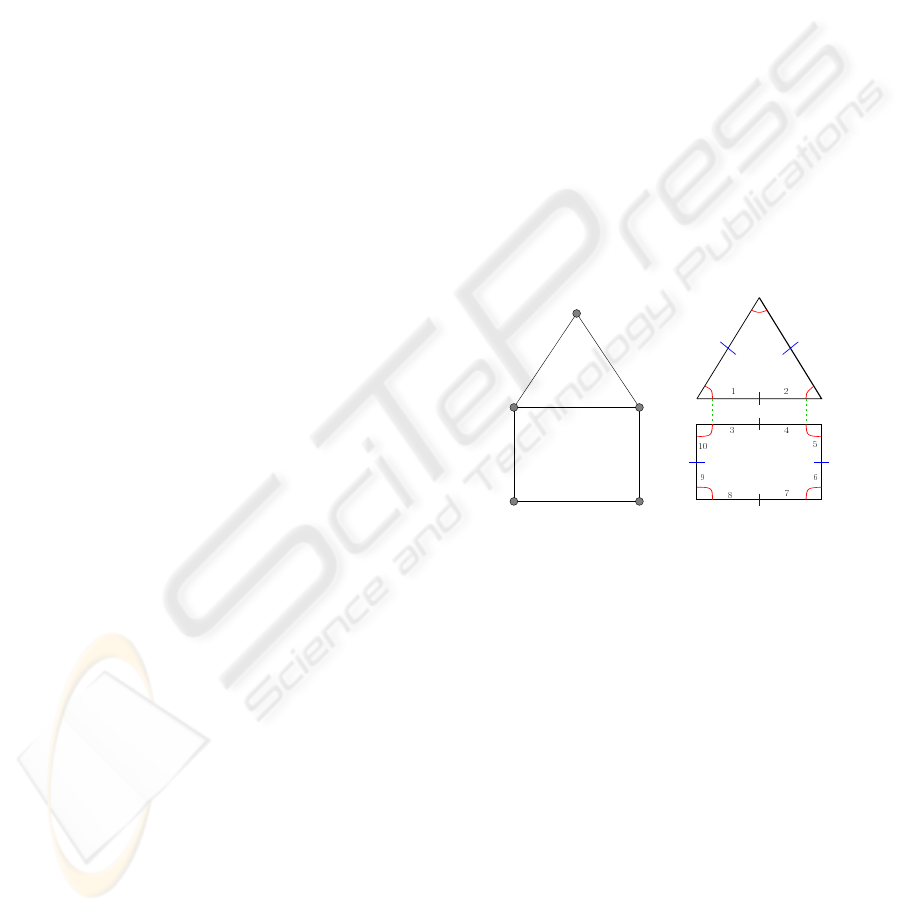
(a) (b)
Figure 2: (a) A 2D object containing 2 faces, 6 edges
and 5 vertices; (b) corresponding generalized map: the
set of darts {1,2,3,4} represents an edge, the set of darts
{3,4,5,6,7,8,9,10} represents a face.
Several topological models allowing space subdi-
visions have been proposed in the literature: struc-
tures containing adjacency graphs (Brisson, 1993),
2D/3D models based on edges (Baumgart, 1975;
Guibas and Stolfi, 1985; Weiler, 1986) or models ca-
pable of handling higher dimensions (Brisson, 1993;
Lienhardt, 1994). As explained in the following sec-
tion, many reasons have motivated our choice for gen-
eralized maps (Lienhardt, 1994).
It has been shown in (Lienhardt, 1991) that exist-
ing topological models representing 3D subdivisions
are comparable with 3D maps (for orientable models
without boundary) or with 3D generalized maps (for
orientable or not models, with or without boundary).
Even though 3D generalized maps are more expen-
sive than 3D maps in the memory, we have chosen
GRAPP 2007 - International Conference on Computer Graphics Theory and Applications
38

this model since it provides a homogeneous represen-
tation in all dimensions. This simplifies many opera-
tion definitions.
From a single type of basic elements (called darts)
and one to one mappings α defined on these darts,
generalized maps represent object cells and adja-
cency/incidence relationships. Each mapping α
i
, with
0 ≤ i ≤ n (n being the highest dimension used), rep-
resents the adjacency relations between i-dimensional
cells;
Definition 1 (Generalized map (Lienhardt, 1994))
A generalized map in dimension n ≥ 0 (or n-G-map)
is an algebra G = (D, α
0
, ..., α
n
), where:
- D is a finite set of darts;
- α
0
, ..., α
n
are involutions
1
;
- α
i
α
j
is
2
an involution for all i, j such that
0 ≤ i < i+ 2 ≤ j ≤ n.
Two darts d and d
′
are α
i
-sewed if dα
i
= d
′
with
d 6= d
′
, and d is α
i
-free if dα
i
= d. The i-cell asso-
ciated with a given dart d is composed of all the darts
obtained by a coverage starting from d and using all
the involutions except α
i
(see figure 2). The number
of distinct edges incident to a vertex defines its de-
gree. When the vertex is incident to only one edge,
the edge is called a dangling edge.
On the basis of this representation, we have
used the 3D topological modeller MOKA (Vidil and
Damiand, 2003), comprising many operations such as
sewing two cells along a face or more complex oper-
ations like sweeping or corefining.
4 2D RECONSTRUCTION
For extruding a 3D building, a valid topology has to
be reconstructed from the 2D plan. Therefore, the
dataset has to comply with three fundamental proper-
ties: (i) edges should not be merged, (ii) edges should
not intersect (iii) edge vertices should all be incident
to another edge. (i) and (ii) ensure that the plan is a
partition of a 2D space in faces, edges and vertices. In
a 2D architectural plan every object is usually defined
with a given thickness. Consequently edges should
not be isolated, which corresponds to (iii). When
these 3 properties are verified, the set of edges is said
valid.
1
A bijection f is an involution iff f
2
= Id
2
If β and γ are applications of E → E, βγ corresponds
to the composition γ ◦ β, and bβγ is the application of this
composition to element b of E.
Unfortunately, modeller software used by archi-
tects is not devised for 3D topological extrusion. Con-
sequently, in most cases, none of the above proper-
ties is maintained. The reconstruction robustness of
our method highly depends on the detection and cor-
rection of all geometrical inconsistencies contained
in the 2D plans. Our application corrects geometry
and builds up the topological model. It is composed
of two parts: the first one consists of geometry error
detection and correction while the second one con-
structs topological information. The final goal is to
link edges so as to produce 2D faces.
In practice, for the plans we have used, 90% of
imprecisions are automatically corrected. However,
some remaining awkward elements have to be pro-
cessed. Therefore, we propose semi-automatic opera-
tions for correcting the plans (see section 4.4).
Semantic information can be deduced from the
plans when it exists, or defined manually by the user.
Finally, each type of object contained in plans is asso-
ciated with semantics: walls, rooms, openings, stairs,
etc.
The general algorithm of 2D reconstruction is bro-
ken up into the following steps: (1) edge extraction
from source file (2) geometry correction (3) topolog-
ical construction (4) semi-automatic finalization (5)
semantics association.
4.1 Geometrical Correction
Once the edges have been identified in the source file,
the plan analysis is performed. Therefore, a threshold
ε is defined for testing whether two edges are super-
imposed and finding all the edges incident to a given
vertex. In practice, we have fixed ε = 1mm.
Two edges are superimposed if they have the same
slope, the same origin ordinate and at least one ex-
tremity included in the other edge. In this case, both
edges are merged into a single one.
All the edge intersections are processed two by
two. If an intersection is found, a vertex is added at
the intersection point on the concerned edges.
4.2 Topological Reconstruction
The above processing produces a set of valid seg-
ments used to construct topology. All the adjacency
and incidence relationships between vertices, edges
and faces have to be defined.
4.2.1 Edges Creation
Each edge is associated with four darts corresponding
in 2D to an edge shared by two faces. Links α
0
and α
2
BUILDING 3D INDOOR SCENES TOPOLOGY FROM 2D ARCHITECTURAL PLANS
39

are immediately set on the corresponding darts. Only
α
1
remain to be processed for creating faces.
Since buildings are orientable objects, composed
of orientable elements, we also need to set an ori-
entation to the whole generalized map. This is why
darts are associated with a boolean mark indicating
the edge orientation. For a dart d marked, dα
0
, dα
1
and dα
2
are not marked.
4.2.2 Angle Arrangement
For 1 and 2-degrees vertices, the corresponding darts
are directly connected by α
1
. For each vertex of
higher degree, the incident edges are stored and sorted
according to their angle around the vertex. The algo-
rithm is the following:
1. search for dart d α
1
-free;
2. search for all darts {d
i
} α
1
-free, incident to d;
3. sort {d
i
} according to the angle with d (corre-
sponding to the angle formed by the associated
edges);
4. α
1
-sew the darts two by two according to this or-
der, with respect to the orientation constraints.
4.2.3 Face Inclusion
In most plans, some objects are included in others.
For instance, stairs are included in rooms. Unfortu-
nately, with boundary representations, these objects
are not connected. Consequently, there is no rela-
tive position between elements. This is why we have
used fictive edges for linking the existing connected
components. On the floor, a fictive edge is thus used
to link an external face to the included ones. These
edges are called fictive edges since they do not repre-
sent the boundary of a face.
4.3 Accelerating Structure
With the process described above, many operations
require testing couples of darts according to their lo-
cation in the plans. The use of an accelerating struc-
ture makes it possible to reduce the processing time.
Since the plans scale is defined in meters, we choose a
uniform grid made up of 1meter× 1meter tiles. Each
tile is associated with the list of segments which cross
it. Thus, for each segment, tests are performed only
in a local neighborhood. Note that segments corre-
sponding to walls only belong to a few tiles.
4.4 Additional Operations
To eliminate inconsistencies that are not auto-
matically corrected, we propose several semi-
automatically operations. Based on the low-level op-
erations sew and removal defined in (Damiand and
Lienhardt, 2003), we propose higher-level operations
for processing several edges at the same time: (i) for
sewing two selected edges; (ii) for sewing several se-
lected dangling edges to the closest edge; (iii) for
sewing all the dangling edges to the closest edge; (iv)
for topologically removing n selected edges.
It can be necessary to add doors on the plans. We
also propose an operation for creating a door, starting
from the selection of two walls. A door is inserted in
the plan, and associated with its semantic.
4.5 Semantic Definition
Semantic information allows the user to know the
type of each element in the plan. The objects are clas-
sified into various categories: walls, doors, floor, ceil-
ing, stairs, etc. Any type of new information can be
conveniently added to the model. In practice, each
dart holds a label corresponding to its semantic.
During the reconstruction process, it is possible to
use the layers contained in the source file for indicat-
ing the semantic of objects. The user can also select
part(s) of the building and manually modify seman-
tics. This information is used for guiding the extru-
sion process described below.
5 3D EXTENSION
The starting point of the 3D extrusion is a 2D plan
composed of faces, edges and vertices associated with
a consistent topology (i.e. an orientable 2D partition,
closed and without dangling edges). Each floor is
handled using several types of operations. Therefore,
we have adapted the extrusion already existing in the
MOKA library. Each type of element is specifically
processed.
The topological 3D representation has to comply
with several important features.
1. The 3D model must be a closed space since each
room, wall and portal are defined as a closed vol-
umes. For instance, rooms are defined by volumes
with transparent faces corresponding to portals.
Consequently, each face should be incident to ex-
actly two volumes. Obviously, faces also have to
be closed as well as edges.
2. Each building must be composed of a single 3D
connected component. For instance, faces or vol-
umes defining holes have to be connected with
their respective faces or volumes.
GRAPP 2007 - International Conference on Computer Graphics Theory and Applications
40
3. The model must be oriented since each part of the
building should be clearly identified as the inside
or the outside.
These constraints are guaranteed by the properties
of the 2D plan and the extrusion operation.
Finally, the building extrusion is organized as fol-
lows: (i) extrusion of the floor (wall, doors), (ii) cre-
ation of the ground and ceiling, (iii) superposition of
floors, (iv) stairs construction.
5.1 Extrusion of Walls
For extruding walls, a vertical path is defined with a
height equal to 2, 5 meters. From each face of the
2D plan, a volume is automatically created and con-
nected using α
3
to the corresponding face (see figure
3). Contrary to existing modeler, our topological ex-
trusion of two faces connected by α
2
produces two
volumes connected by α
3
. Note that fictive edges are
not extruded so that no useless fictive face be created.
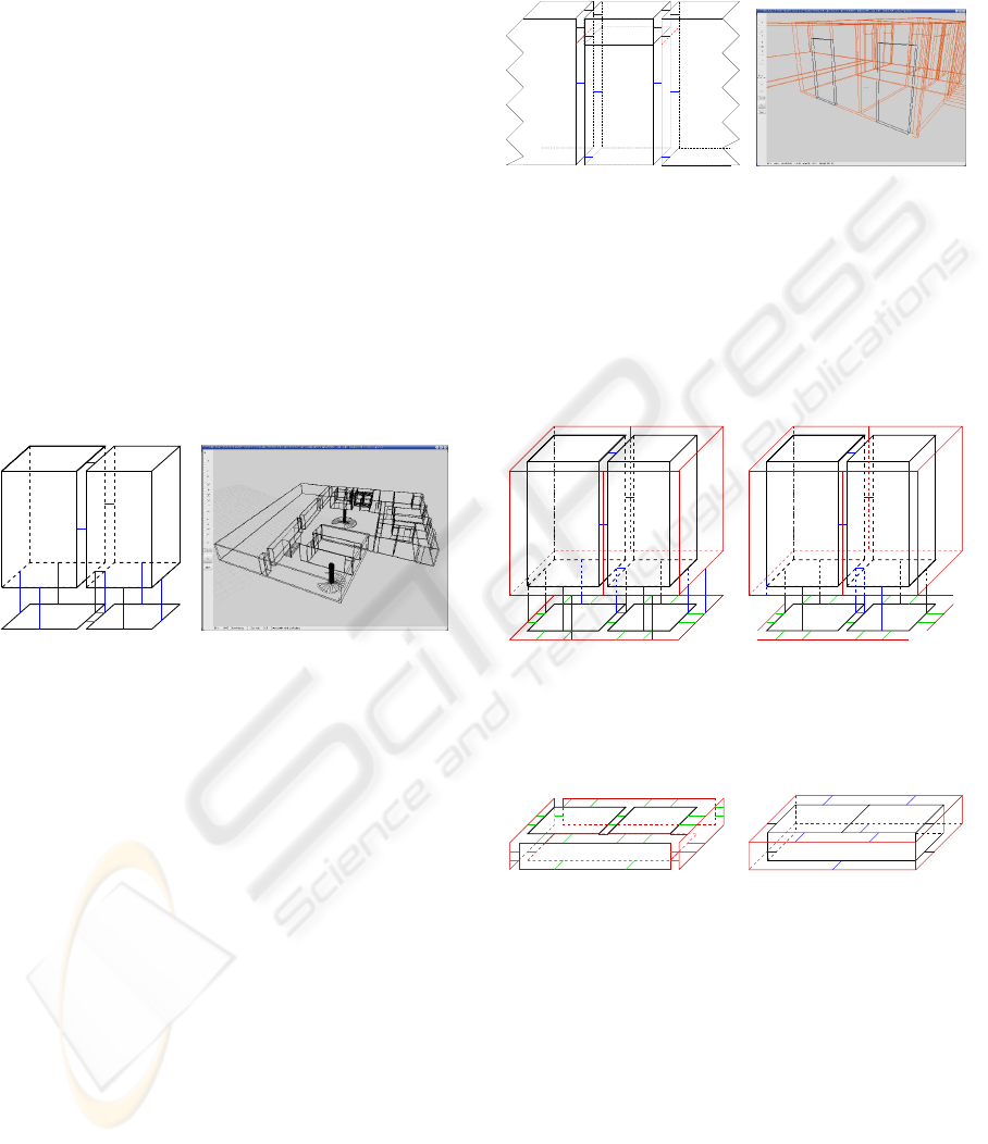
V1 V2
F1 F2
α
2
α
3
α
3
α
3
α
3
(a) (b)
Figure 3: Extrusion of walls: (a) volumesV
1
andV
2
are built
and connected to the corresponding faces F
1
and F
2
. Since
F
1
and F
2
are connected by α
2
, V
1
and V
2
are connected by
α
3
. (b) sample floor with walls extrusion.
The extrusion operation defined above allows the
construction of non vertical walls (the extusion path
has to be properly defined). However, in most cases
the slope is not defined on the plans. Moreover, the
modeler MOKA can be easily used for modifying the
upper wall edges.
5.2 Extrusion of Opennings
On the plans, door volumes are topologically con-
nected to the surrounding walls. The portion of wall
above to the door is created. Therefore, the 2D poly-
gon representing the door is extruded according to a
vertical path of two components (corresponding to the
opening and the portion of wall above the door). The
two resulting volumes are superimposed and topolog-
ically connected. In a second step, they are connected
to the remainder of the building, along the door stiles.
Two vertices and an edge must be inserted on the
stiles to respect the topological constraints (figure 4).
For windows, the same operation can be applied
with an additionnal component corresponding to the
wall part located under the window.
DOOR
W1
W3
E2
W2
V4
V1
V2
E1
V3
(a) (b)
Figure 4: Door extrusion: (a) extrusion and connexion to
the walls W
1
and W
2
, the section of wall named W
3
is built
above the door. Four vertices (V
1
,V
2
,V
3
,V
4
) and two edges,
A
1
and A
2
, are inserted on M
1
and M
2
. (b) Result of door
extrusion.
5.3 Creation of Grounds and Ceilings
V1 V2
F1 F2
α
2
α
3
α
3
α
3
α
3
(a)
V1 V2
F1 F2
α
2
α
3
α
3
α
3
α
3
(b)
Figure 5: (a) Contour faces are marked for being used dur-
ing the creation of the floor; (b) α
1
and α
3
are unsewed for
the 2D plan contour.
F1 F2
(a)
F1 F2
(b)
Figure 6: Ground creation: (a) the 2D plan contour is used
to construct the ground volume; (b) the ground volume is
closed (red volume corresponding to the outer part).
With the extrusion system described above, the
darts of the 2D plan are α
3
-connected to volumes
defining walls or doors (figure 5.a).
The 2D plan is used to create the ground volume
(flagstone). Therefore, the contour of the 2D plan
is α
1
and α
3
-disconnected (figure 5.b) and the corre-
sponding edges are used to form the desired volume
(Figure 6). The external faces of this volume are α
2
-
sewed with the faces representing the floor contour
(figure 7).
BUILDING 3D INDOOR SCENES TOPOLOGY FROM 2D ARCHITECTURAL PLANS
41
F1 F2
(a)
F1 F2
(b)
Figure 7: (a) The outer ground volume is sewed by α
2
to the
extern floor volume (facade); (b) the resulting open volume
(in red) represents the floor facade and the ground.
F1 F2
F’1 F’2
(a)
F1 F2
(b)
Figure 8: Ceilings creation: (a) the horizontal faces at the
top of the floor are duplicated; (b) duplicated faces are used
for creating the ceiling volume with the same method as for
grounds. The resulting closed volume describes the facade
and actually defines the rest-of-the-world volume.
The construction of the ceiling requires the copy
of the 2D plan at the top of the floor (Figure 8.a). Dur-
ing duplication, each new dart is sewed by α
3
to its
corresponding dart. The external segment is used to
construct the ceiling volume (Figure 8.b). The exter-
nal faces are sewed by α
2
with the darts of the 3D
floor contour. This operation produces 4 types of vol-
umes: ground, ceiling, indoor description, facade.
5.4 Superimposing of Floors
For superimposing two floors with same outer 2D
shape, the ground of the upper floor is connected to
the ceiling of the lower floor (Figure 9). In practice,
the two volumes are sewed by α
3
and the shared face
is removed. Thus, only one volume defines the space
between the two floors.
5.5 Creation of Stairs
Stairs can be defined with various shapes on the 2D
plans: straight, snail, elliptic, etc. They are often
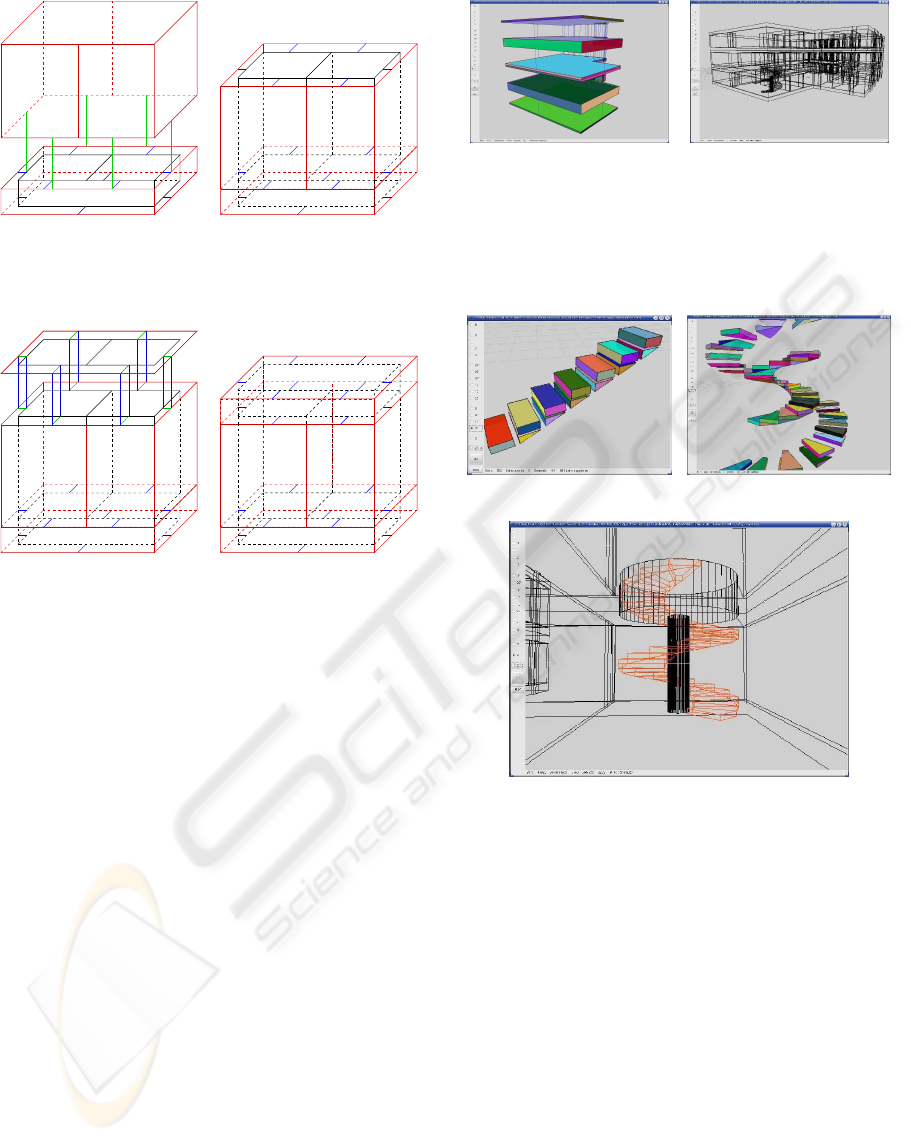
(a) (b)
Figure 9: Creation of grounds and ceilings. (a) Visualiza-
tion of the connections between the grounds and ceilings of
two floors. The ceiling of the lower floor and the ground of
the upper floor are merged. (b) Building made up of two
superimposed floors.
(a) (b)
(c)
Figure 10: Construction of stairs. (a) Steps of a straight
staircase composed of two volumes. (b) Volumes defining
snail stairs. (c) Result of snail stairs in a building with ceil-
ing opening.
disconnected from the rest of the plan or joined to
the walls. We propose a generic method for creat-
ing the stairs topology. The steps geometry is com-
puted according to the data recovered on the plan
(length, width, or diameter in the case of spiral stairs).
Presently, our method does not provide any automatic
system for detecting the geometric type of stairs, the
user manually selects the appropriate method.
Each step is composed of two volumes (figure
10.a). A surrounding volume ensures the model
closeness (figure 10.b). Once created, the 3D stair
is connected to the remainder of the plan by a fic-
tive edge. The ceiling is perforated according to the
stair shape using of a boolean operation. Therefore
the stair contour is extruded according to the ceiling
GRAPP 2007 - International Conference on Computer Graphics Theory and Applications
42
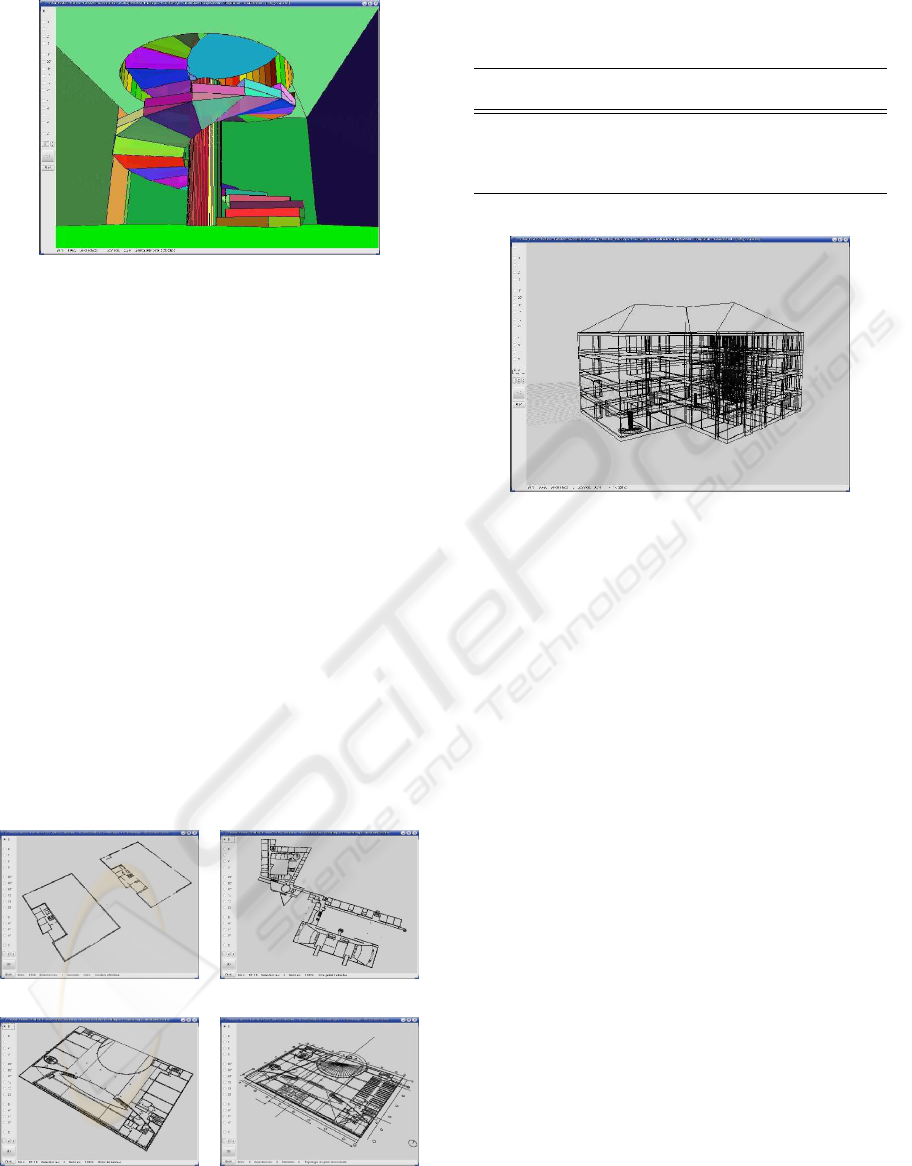
Figure 11: Result of 3D stair reconstruction.
height and the resulting volume is subtracted from the
ceiling so as to create the opening (Figure 11).
6 IMPLEMENTATION AND
RESULTS
Our reconstruction system has been implemented in
C++, using the MOKA library (Vidil and Damiand,
2003). The source files have been produced by ar-
chitects in dxf format. Computing times have been
obtained with a centrino processor: 2Ghz and 1GB of
RAM.
We have applied our reconstruction method to var-
ious 2D architectural plans. The processing times for
the 2D analysis are presented Table 1. They depend
on the distribution of the segments in the plan and
on the uniform grid acceleration. The processing of
a floor never exceeds one minute, even for complex
plans.
(a) plan 1 (b) plan 2
(c) plan 3 (d) plan 4
Figure 12: Plans used for geometrical and topological re-
construction.
Table 1: Processing time of the automatic 2D reconstruc-
tion.
Buildings # Segments Geometric Topological
of the scene processing processing
plan 1 899 2s 1s
plan 2 8050 9s 16s
plan 3 8120 11s 13s
plan 4 11972 56s 59s
Figure 13: Result of reconstruction 3D.
With the proposed method, 90% of the plans inco-
herencies have been detected and corrected automat-
ically. The time required for manually correcting the
2D models incoherencies is about a few hours, de-
pending on the model complexity and the numbers
of errors contained in the plan. From this point, the
3D reconstruction becomes completely automatic and
takes only a few seconds. Moreover, all the topo-
logical and semantical information are automatically
propagated.
7 CONCLUSION
This paper presents a new method for reconstructing
a 3D description of buildings from 2D architectural
plans. The resulting description includes geometry
and topology so that the whole environment consis-
tency be preserved according to constraints such as
closeness, orientability, and connectivity.
The main steps of our method concern: (i) a geo-
metrical correction of source data, (ii) a 2D topology
construction, (iii) a 3D extrusion system, (iv) floors
superimposing. We also propose semi-automatic
tools for correcting 2D plans. The results obtained
show that 2D and 3D processing require only a few
tens of seconds.
The main advantage of our method concerns the
use of topology for validating the building structure
coherence and editing the model using modelling op-
BUILDING 3D INDOOR SCENES TOPOLOGY FROM 2D ARCHITECTURAL PLANS
43

erations. Furthermore, the resulting structure pro-
vides various types of information necessary for vi-
sualization or lighting/thermal/low-frequency wave
propagation simulations (Meneveaux et al., 1998a;
Fradin et al., 2005; Teller et al., 1994).
The next step of this work consists in automat-
ically defining additional semantics (such as rooms
or furniture for instance). Thus operations dedicated
to volume types can be explored for simplifying the
3D models. We also aim at automatically detecting
stairs and their characteristics. Moreover, additional
operations have to be defined, for instance related to
windows, roofs or superimposed floor with different
shapes.
In the future, we wish to apply our system to ur-
ban scenes as well, containing furnished buildings,
etc. This implies the processing of larger data with
missing information. We aim at coupling our system
with procedural reconstruction methods.
REFERENCES
Ah-Soon, C. (1998). Analyse de Plans Architecturaux. Phd
thesis, INPL.
Airey, J. M., Rohlf, J. H., and F. P. Brooks, J. (1990). To-
wards image realism with interactive update rates in
complex virtual building environments. In ACM Sym-
posium on Interactive 3D Graphics, pages 41–50.
Baumgart, B. (1975). A polyhedron representation for com-
puter vision. In AFIPS Nat. Conf. Proc. 44, pages
589–596.
Brisson, E. (1993). Representing geometric structures in d
dimensions : topology and order. Discrete & Compu-
tational Geometry, 9:387–426.
Damiand, G. and Lienhardt, P. (2003). Removal and con-
traction for n-dimensional generalized maps. In Dis-
crete Geometry for Computer Imagery, number 2886
in Lecture Notes in Computer Science, pages 408–
419, Naples, Italy.
Fradin, D., Meneveaux, D., and Horna, S. (2005). Out-of-
core photon-mapping for large buildings. Eurograph-
ics Symposium on Rendering EGSR 2005, Konstanz,
Germany.
Fuchs, F., Jibrini, H., Maillet, G., Paparoditis, N., Deseil-
ligny, M., and Tailandier, F. (2003). Trois approches
pour la reconstruction automatique de modle 3-d de
btiments en imagerie arienne haute rsolution. Bulletin
d’information de l’IGN n73 (2002/2003), pages 17–
26.
Guibas, L. and Stolfi, J. (1985). Primitives for the ma-
nipulation of general subdivisions and the computa-
tion of voronoi diagrams. Transactions on Graphics,
4(2):131–139.
Lienhardt, P. (1991). Topological models for boundary rep-
resentation: a comparison with n-dimensional gener-
alized maps. Computer-Aided Design, 23(1):59–82.
Lienhardt, P. (1994). N-dimensional generalized combi-
natorial maps and cellular quasi-manifolds. Interna-
tional Journal of Computational Geometry & Appli-
cations, 4(3):275–324.
Meneveaux, D., Bouatouch, K., and Maisel, E. (1998a).
Memory management schemes for radiosity computa-
tion in complex enviroments. In Computer Graphics
International.
Meneveaux, D., Bouatouch, K., Maisel, E., and Delmont, R.
(1998b). A new partitioning method for architectural
environments. Journal of Visualization and Computer
Animation, 9(4):195–213.
Muller, P., Wonka, P., Haegler, S., Ulmer, A., and Gool,
L. V. (2006). Procedural modeling of buildings. ACM
Trans. Graph., 25(3):614–623.
Parish, Y. I. H. and Muller, P. (2001). Procedural modeling
of cities. Computer Graphics (ACM SIGGRAPH’01
Proceedings).
Teller, S. (1992). Computing the antipenumbra of an
area light source. In Computer Graphics (ACM SIG-
GRAPH’92 Proceedings).
Teller, S., Fowler, C., Funkhouser, T., and Hanrahan, P.
(1994). Partitioning and ordering large radiosity
computations. In Computer Graphics (ACM SIG-
GRAPH’94 Proceedings), pages 443–450.
Vidil, F. and Damiand, G. (2003). Moka.
www.sic.sp2mi.univ-poitiers.fr/moka/.
Weiler, K. (1986). The radial-edge data structure: a
topological representation for non-manifold geometry
boundary modeling. In Proc. IFIP WG 5.2 Working
Conference, Rensselaerville, USA.
GRAPP 2007 - International Conference on Computer Graphics Theory and Applications
44
