
AN ENHANCED EDGEBREAKER COMPRESSION ALGORITHM
FOR THE CONNECTIVITY OF TRIANGULAR MESHES
D. R. Khattab, Y. M. Abd El-Latif, M. S. Abdel Wahab and M. F. Tolba
Faculty of Computers and Information Sciences, Ain Shams University
Abbassia, 11566, Cairo, Egypt
Keywords: Triangle mesh compression, EdgeBreaker, Connectivity encoding, Linear decoding.
Abstract: Compression of digital geometry models is the answer to an industrial demand. Over the last years, many
exciting ideas and new theoretical insights have been devoted to finding ways of reducing the amount of
storage such models absorb. EdgeBreaker is one of the effective lossless single-rate connectivity
compression techniques for triangular meshes. This paper presents an enhanced EdgeBreaker encoding
algorithm which solves the problem of non-linearity of EdgeBreaker decoding procedure while
reconstructing the mesh triangles in the same order they were traversed during the encoding phase. The new
enhancement is based on the same data structure: the corner-table used by EdgeBreaker however, it
eliminates some of the computational overhead exhibited by EdgeBreaker compression. This enhanced
technique also yields to significantly smaller rates for connectivity compression than EdgeBreaker. It
achieves an average compression ratio of 1.8 bit per triangle and 3.57 bit per vertex for the used benchmark
3D models.
1 INTRODUCTION
Interactive display of 3D content has been
extensively used in many applications ranging from
electronic commerce to the virtual game industry.
Among several representations, polygonal meshes
are used most often as surface representation (Abd
El-Latif, Ghaleb and Hussein, 2006) because of
their wide spread support in many file formats and
graphics libraries. These large and complex meshes
are becoming commonplace because of the
increasing capabilities of the computing
environments, visualization hardware, modern
interactive modelling tools and semi automatic 3D
data acquisition systems. The complexity of these
models poses basic problems of efficient storage in
file servers, transmission over computer networks,
rendering, analysis, processing etc. for these reasons
it was desirable to compress polygonal meshes to
reduce storage and transmission time requirements.
Geometry compression techniques for such very
large 3D geometric models have thus become a
subject of intense study in recent years. The
compression approach is one of the primarily
approaches for reducing the size of a mesh. It
depends on deriving a new encoding for the
polygonal mesh such that the total number of bits
needed in the new encoding is much lower than the
number needed for the uncompressed representation.
Large body of compression research has
concentrated on clever encoding of the mesh
connectivity. Typically (Shikhare, 2000), the
number of triangles in a mesh is roughly twice the
number of vertices and each vertex is referenced in 5
to 7 triangles, which means that large part of the
representation of the model is in the definition of
connectivity. Also the combinatorial graph structure
of the mesh connectivity allows it to be coded
losslessly, so it can be restored to the original model
after decoding.
Prior Works. Much of the work in the area of
single-rate connectivity compression has been
concerned with triangle meshes only (Allie and
Gotsman, 2005) This is because the triangle is the
basic geometric primitive for standard graphics
rendering hardware and also it can be easily derived
from other surface representations. Many
compression schemes have been emerged recently
using different approaches such as focusing on
hardware decoding (Deering, 1995 and Chow,
1997), applying mesh traversal (Gumhold and
Strasser, 1998 and Rossignac, 1999) and using
valence-based incidence compression (Touma and
Gotsman, 1998 and Alliez and Desbrun 2001).
109
R. Khattab D., M. Abd El-Latif Y., S. Abdel Wahab M. and F. Tolba M. (2007).
AN ENHANCED EDGEBREAKER COMPRESSION ALGORITHM FOR THE CONNECTIVITY OF TRIANGULAR MESHES.
In Proceedings of the Second International Conference on Computer Graphics Theory and Applications - GM/R, pages 109-115
DOI: 10.5220/0002074301090115
Copyright
c
SciTePress

Among these techniques, EdgeBreaker (Rossignac,
1999) is considered one of the best connectivity
compression techniques for compressing simple
manifold triangular meshes that are homeomorphic
to a sphere. It achieved bit rates of 2 bit per triangle
(bpt) and 4 bit per vertex (bpv). As this result was
the best achieved so far, many derivatives of the
EdgeBreaker algorithm had appeared. Using a
slightly more complex code, King and Rossignac
(King and Rossignac, 1999) guaranteed that the
compressed file will not exceed 1.83t bits and 3.67v
bits. The algorithm was further optimized for
meshes with regular connectivity (Szymczak, King
and Rossignac, 2001). In (Rossignac, Safonova and
Szymczak, 2002) the same algorithm was introduced
with a simple data structure, the Corner-Table for
representing the connectivity of triangle meshes.
Again the algorithm was extended with a simple
formulation to deal with triangulated surfaces with
handles (Lopes, Rossignac, Safonova, Szymczak
and Tavares, 2003). Finally the authors in (Lewiner,
Lopes, Rossignac, and Vieira 2004) provided
efficient extensions of the EdgeBreaker compression
which enables to use the EdgeBreaker algorithm to
encode the connectivity of a surface, possibly having
any number of connected components, handles or
boundary curves.
While the encoding scheme of EdgeBreaker
(Rossignac, 1999) exhibits a linear storage cost,
some preliminary preprocessing steps were required
in the decoding phase making it exhibits a non-linear
time complexity of O(n
2
). More recent work
(Rossignac and Szymczak, 1999) eliminated the
need for this look-ahead procedure and improved the
worst case complexity to O(n). However this
algorithm requires multiple traversals of the mesh
triangles for meshes with handles and an initial
traversal of the encoding for meshes with boundary.
Another simple decoding technique (Isenburg and
Snoeyink, 2001) was developed that recreates the
triangles encoded by EdgeBreaker in linear time
unless this was done in the reverse order these
triangles were encoded.
Contributions. The main work of this paper is
based on the work of EdgeBreaker (Rossignac,
Safonova and Szymczak, 2002) developed by
Rossignac et al. The EdgeBreaker encoding
procedure is enhanced to allow the decoding phase
to be implemented in linear time complexity without
any additional preprocessing and in the same order
the mesh is traversed during the encoding phase.
Further more, this enhancement eliminates the
computational overhead implemented by using extra
data structures and also improves the compression
ratio generated by the original procedure (Rossignac,
1999) to 1.8 bpt and 3.57 bpv.
The remainder of this paper is organized as
follows: in the next section the EdgeBreaker
encoding and decoding schemes are explained. A
detailed description of the algorithm can be found in
(Rossignac, 1999 and Rossignac, Safonova and
Szymczak, 2002). Section 3 illustrates the new
improvement done to the encoding algorithm of
EdgeBreaker. The results and discussions are
presented in section 4 and we conclude in section 5.
2 EDGEBREAKER ENCODING
AND DECODING
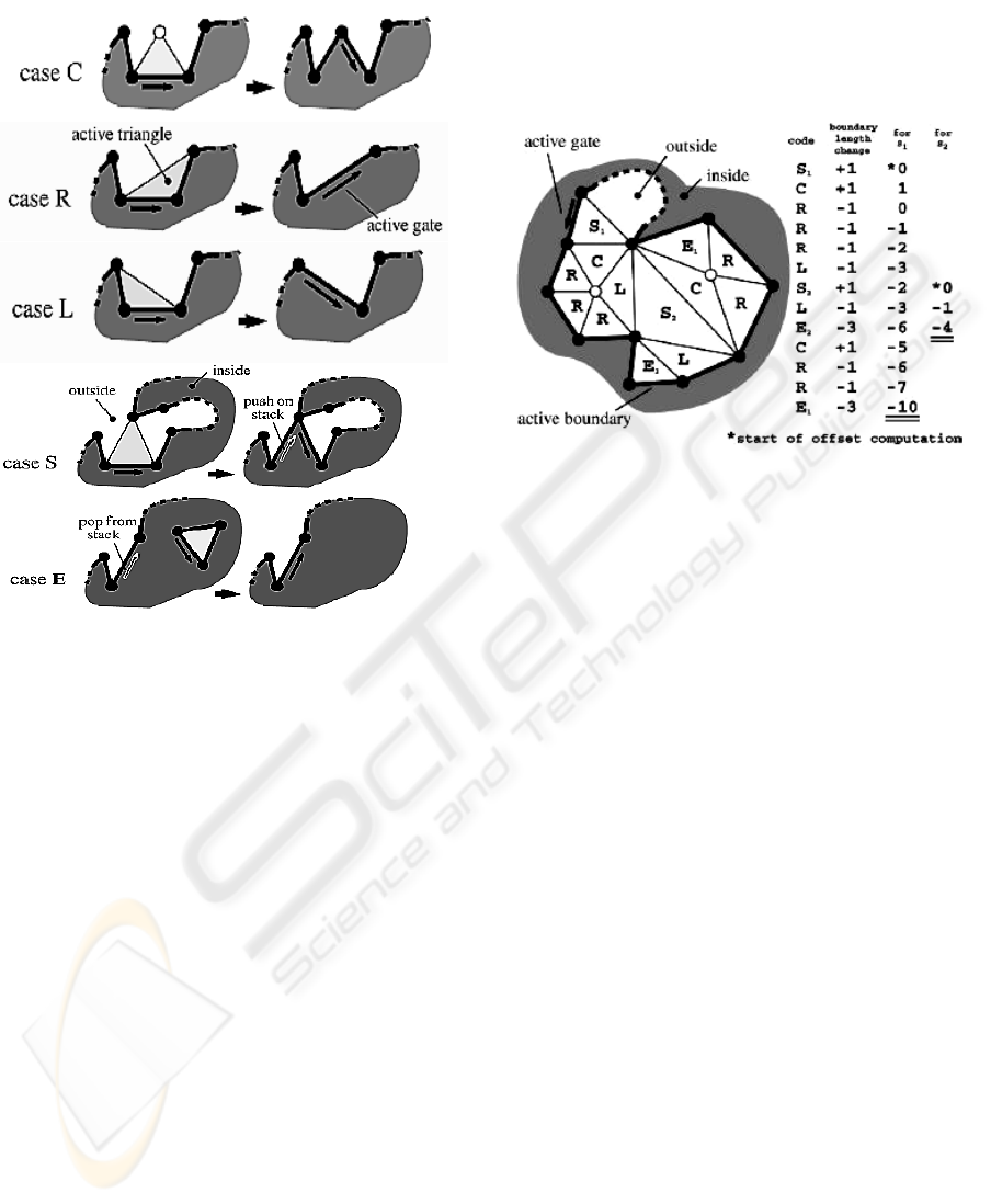
The EdgeBreaker encoding process visits the
triangles in a spiraling (depth-first) order and
produces a CLERS string. The CLERS string
includes five different operations called C, L, E, R,
and S. The encoding process starts off with picking
an arbitrary triangle of the mesh as an initial active
boundary. One of the three initial boundary edges is
defined to be the gate of the boundary. An initially
empty stack is used to temporarily store boundaries.
This process terminates after t-1 operations, with t
being the number of mesh triangles. Which
operation is chosen depends on how the respective
triangle is attached to the active boundary at the
moment it is processed (Figure 1). If its third vertex
is not on the active boundary then operation C is
used and the new gate is the right edge of the old
gate. If the third vertex is the next boundary vertex
then operation R is used. If it is the previous
boundary vertex then operation L is used. In both R
and L operations the new gate is the inserted
boundary edge. If the third vertex is some other
boundary vertex, then operation S is used. The left
edge of the old gate is pushed on the stack and the
other becomes the active gate. If the third vertex is
the previous and the next boundary vertex then
operation E is used. This can only happen for an
active boundary of length three.
For triangle meshes with v vertices and t
triangles that are homeomorphic to a sphere, t equals
2v-4 (Rossignac, 2003). Because, except for the first
two vertices, there is a one-to-one mapping between
each C triangle and each vertex, the number of C
triangles is v–2. Consequently, the number of non-C
triangles in a simple mesh is t–(v–2), which is also
v–2. Thus exactly half of the triangles are of type C.
using A straight-forward compression scheme that
uses the following simple binary code for the labels
GRAPP 2007 - International Conference on Computer Graphics Theory and Applications
110
(C=0, L=110, E=111, R=101, S=100) is guaranteed
to use no more than 2t or 4v bits.
Figure 1: EdgeBreaker encoding operations.
The EdgeBreaker decoding process starts with a
CLERS string and produces a triangulated mesh.
Two traversals of the CLERS string are needed: The
preprocessing phase computes an offset value for
every S operation. The offset value is the distance
between the active gate and the tip vertex along the
active boundary. These offset values are calculated
by adding up the resulting change in boundary
length for all operations following an S operation
until and including its corresponding E operation.
Since pairs of S and E operations are always nested,
the offset values for all S operations can be
computed in a single traversal (Figure 2).
The other decoding phase is the generation phase
which creates the triangles in the same order they
were encoded by the EdgeBreaker encoding process.
It starts with creating the initial triangle. The active
boundary and the gate are identified and the CLERS
string is processed. For the C operation a new vertex
is created. For all other operations a vertex from the
active boundary is used. For the R operation the
third vertex is the next vertex on the active boundary
and for the L operation the third vertex is the
previous vertex on the active boundary. For the S
operation the precomputed offset value is used.
When the E operation occurs, the active boundary
consists of only three boundary edges leaving no
choice for the third vertex. If the active boundary is
maintained in a linear data structure, each S
operation will require a linear search for the vertex
specified by the offset implying an asymptotic worst
case time complexity of O(n
2
) for the EdgeBreaker
decoding.
Figure 2: EdgeBreaker decoding operations.
3 ENHANCED EDGEBREAKER
ENCODING
The breakthrough of EdgeBreaker lies in the
discovery that the locations of the tips of the S
triangles need to be stored neither as integer
references nor as offsets which separate the gate
from the tip location in the current loop. They
discovered that these offsets can be recomputed by
the decoding algorithm from the CLERS string
itself. This solution minimizes the encoding size and
improves the compression ratio while it leads for the
nonlinearity of the decoding algorithm. The new
enhancement of EdgeBreaker tries to keep
advantage of not saving the offsets as part of the
encoding while in the same time eliminate the need
of computing them as a preprocessing stage during
decompression.
The S triangle in EdgeBreaker compression
scheme splits the active boundary into two, one on
each side of the S triangle. The algorithm then tends
to fill the hole generated in the mesh surface on the
right side of the S triangle before returning to the left
one. This required keeping a stack for storing the left
edge of every S triangle to be the next active gate
(Figure 3a). The new enhancement developed here
performs the same traversal of the EdgeBreaker
compression but only differs in the way it deals with
the S triangles. Whenever an S triangle is reached,
the algorithm tends to ignore encoding it at the
moment and the active gate is changed to another
AN ENHANCED EDGEBREAKER COMPRESSION ALGORITHM FOR THE CONNECTIVITY OF TRIANGULAR
MESHES
111
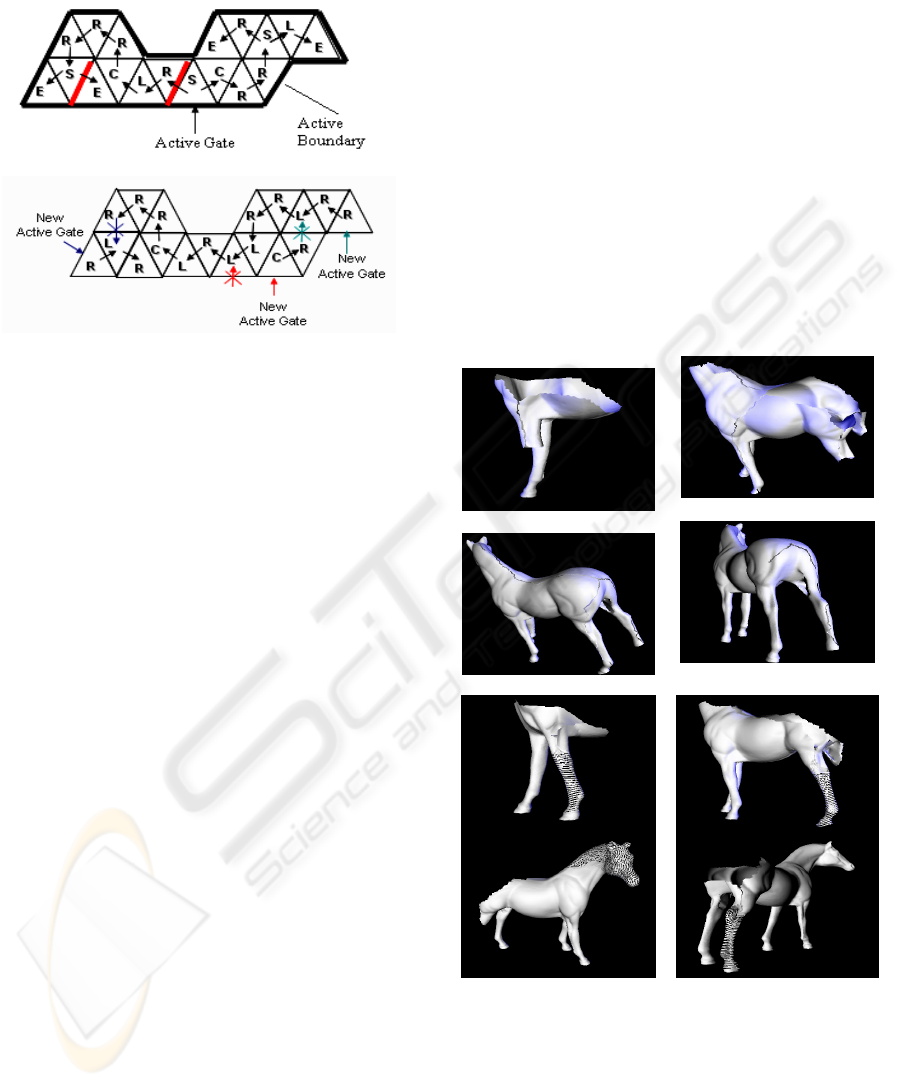
location and then the traverse keeps going on. This
is done by moving on the active boundary one step
to the right of the current active gate (Figure 3b).
(a)
(b)
Figure 3: Encoding example of the final eighteen
operations of a mesh. (a) EdgeBreaker encoding, The red
edges show the ones being stored in the stack; (b)
Enhanced EdgeBreaker encoding, The arrows show how
the active edge is changed during traversal.
This approach ensures that all the previously
ignored S triangles are going to be revisited again as
long as they are not encoded so far but from another
gate – usually the pervious right edge – which will
change the triangle state to an L triangle. This
enhancement eliminates the case of S and E triangles
from the CLERS string while it presents another
symbol M that does not interpret a triangle case but
only tells the decoding algorithm that the current
active gate will be changed to another location some
where on the active boundary just right to the current
one. Keeping the same notations of the C, L and R
triangles, the encoding string has been changed to
the CLRM string. The elimination of the S case from
the encoding string makes the active boundary never
split. The algorithm in this case needs only to
maintain one circular linear list for active boundary
during compression and decompression. In addition,
the enhanced technique has eliminated both the
recursive overhead exhibited by the original
EdgeBreaker compression algorithm and the
computational overhead needed by the stack to keep
list of new active gates generated after splitting.
During the decompression process it eliminates the
need for the preprocessing step, the algorithm only
traverses the encoded string once to regenerate the
mesh triangles in the same order they were encoded
and thus maintaining a linear time complexity of the
decoding process O(n).
While the first version of the developed
enhancement algorithm adopted the idea of moving
to the right of the active gate whenever an S triangle
is reached, a serious problem has emerged. The
original encoding algorithm of EdgeBreaker ensures
that all the triangles in the hole generated to the right
of the S triangle are visited before directing to the
left one. Instead the modification applied here so far
by the enhanced algorithm does not maintain this
feature, meaning that the algorithm can traverse part
of the mesh right to the S triangle and then bypass it
in its reverse course - without encoding - to the other
part of the mesh surface on its left. While the
implemented linear list of boundary edges is
circular, it means that this track can be repeated for
many levels. At each level both areas of the mesh
surface to the left and right of the original S triangle
is being shrinking, giving a chance for other S
triangles to appear until leading to a very long strip
of consecutive S triangles.
(a)
(b)
Figure 4: Steps of mesh generation for the Horse model.
(a) Using the CLRM string; (b) using the CLRGF string.
Notice the long line of un-encoded triangles
generated along the mesh while traverse (figure 4a).
This line begins to appear in parts of the mesh
wherever the boundary tends to meet at a closed
point. In the horse example the line first begins to
GRAPP 2007 - International Conference on Computer Graphics Theory and Applications
112

appear in the front left leg, extends to the horse
neck, the back left leg and then to the back right leg
respectively. This long strip will not be encoded
until one of the mesh surfaces on the right or the left
of the original S triangle is encoded completely. This
long strip which is traversed many times will result
in much increase in the encoding string size and
hence lead to minimize the compression ratio instead
of trying to maximize it.
In order to solve the emerging problem of the
long chain of S triangles, the second version of the
enhanced algorithm updated the procedure to allow
moving along the active boundary either to the right
or to the left of the current active gate whenever an S
triangle is reached. This choice is decided according
to which boundary on the right or the left is shorter
in length. The boundary length is calculated by the
number of edges it contains. The M symbol is now
replaced by other two symbols G and F which are
used to differentiate between either to move one step
to the right or to the left of the current active gate.
The final encoding string introduced by the
enhanced EdgeBreaker compression scheme
becomes the CLRGF string. Figure 4b shows that
the problem of the long chain of un-encoded
triangles previously mentioned does not exist any
more. Each of the four parts of the horse example is
encoded completely before directing to another part
of the mesh. The pseudo-code of the proposed
encoding procedure is provided in the frame below.
Input:
Connectivity and geometry of the mesh in
the CornerTable format.
Output:
CLRGF string that contains one symbol per
triangle except for the first triangle.
Procedure Compress()
While (True)
If tip vertex is not visited Then
Append encoding of C to the CLRGF string,
Add tip vertex to the list of vertices,
Mark triangle and tip vertex as visited,
Update active gate to the right edge of the
old gate input
Else If right triangle was visited Then
Append encoding of R to the CLRGF string,
Mark triangle as visited,
If left triangle was visited Then
End Procedure
Else
Update active gate to the new inserted
boundary edge
Else If left triangle was visited Then
Append encoding of L to the CLRGF
string,
Mark triangle as visited,
Update active gate to the new inserted
boundary edge
Else
Calculate right and left boundary lengths
If the right boundary length is less than
the left boundary length Then
Append encoding of G to the CLRGF
string,
Update active gate to the right edge of
the old one
Else
Append encoding of F to the CLRGF
string,
Update active gate to the left edge of
the old one
4 RESULTS AND DISCUSSION
Table 1 presents the data of the test case meshes
shown in Figure 5. All the meshes are triangular,
manifold, without boundary, holes or handles.
Associating the following binary code based upon
Huffman coding (Huffman, 1952) for the labels
(C=0, R=10, L=110, G=1110, F=1111) used in the
CLRGF string leads to the best compression ratio
that can be achieved. This selection is based on a
study of the average percentage each symbol
consumes from an encoding file generated to each of
the 3D models used.
Table 1: Used benchmark 3D models.
File name File size
No of
triangles
No of
vertices
Retinal 240 KB 7,282 3,643
Cow2 304 KB 8,626 4,315
Smooth-
feature
416 KB 12,350 6,177
Egea 534 KB 16,532 8,268
Head 1 MB 32,744 16,374
Horse 4.62 MB 96,966 48,485
Armadillo 11.9 MB 345,944 172,974
Vase-Lion 14.6 MB 400,000 200,002
AN ENHANCED EDGEBREAKER COMPRESSION ALGORITHM FOR THE CONNECTIVITY OF TRIANGULAR
MESHES
113
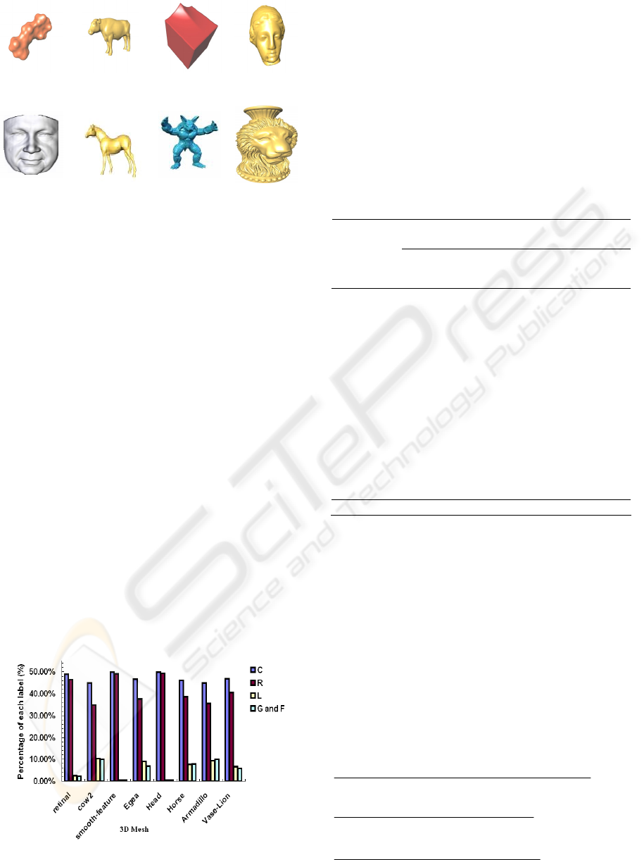
It is apparent from figure 6 that the largest
percentage of the triangles is of type C; this is
because each C triangle is related with the
introduction of a new vertex in the sequence of mesh
vertices. The percentage of R triangles is very close
from the C one; they both consume about 88.72 %
on the average from the total number of symbols
used to encode a mesh. The rest of the symbols is
distributed between L triangles and symbols G and F
which give an indication of finding an S triangle and
so the need of movement along the boundary list.
The two percentages of L; and G plus F together are
very close. This ensures that most of the S triangles
which were ignored for the first time during
traversal are encoded afterwards as L triangles.
Table 2 lists the compressed file size written in
binary format and the compression ratio achieved in
file size, per triangle and per vertex for every test
case of the 3D models used. The compression results
vary from 1.52 bpt and 3.04 bpv (Head example) to
2.16 bpt and 4.31 bpv (Cow2 example). This
variation is due to the different percentage of S
triangles occurrence during mesh traversal which
leads to the addition of symbols G or F to the
encoding string (Figure 6).
Figure 6: Frequency percentage each symbol consumes
from encoding data file.
This percentage of occurrence depends mainly
on the shape characteristics and it represents the
main parameter controlling the compression ratio
that can be achieved to the mesh. It appears from the
used examples that the largest occurrence which
leads to the smallest compression ratio in file size
happens to the Cow2, Armadillo and Horse
examples respectively. This is due to their shape
characteristics; legs of the Horse and Cow2
examples and legs and arms of the Armadillo
example.
Table 2: Comprssion results.
Connectivity
size
Compression ratio
File name
Unco
mpres
sed
Comp
ressed
KB
file
size %
bpt bpv
Retinal
124
KB
1.47 98.8 1.61 3.23
Cow2
172
KB
2.3 98.65 2.16 4.31
Smooth-
feature
222
KB
2.35 98.94 1.52 3.05
Egea
304
KB
4 98.68 1.89 3.77
Head
608
KB
6 99.01 1.52 3.04
Horse
1.87
MB
24.21 98.7 1.99 3.99
Armadillo
6.95
MB
93.04 98.66 2.15 4.30
Vase-Lion
8.9
MB
91.26 98.97 1.83 3.65
Average
98.92 1.8 3.57
According to the binary code associated to each
symbol, an average compression ratio of 1.8 bit per
triangle and 3.57 bit per vertex is achieved. This
result is improved over the results obtained by
EdgeBreaker (Rossignac, 1999) and its derivative
(King and Rossignac, 1999). Connectivity
information is compressed according to the file size
with an average of 98.92%. The encoding algorithm
is also barely sensitive to the seed triangle; therefore
a random face can be selected without affecting the
achieved results much. The compression ratios of
connectivity file size, in bit per triangle and in bit
per vertex are calculated according to equations 1, 2
and 3 respectively.
bits ed uncompress of No.
bits compressed of no. - bits ed uncompress of No.
(1)
trianglesof No.
bitsity connectiv compressed of No.
(2)
verticesof No.
bitsity connectiv compressed of No.
(3)
Retinal Cow2
Smooth-
feature
Egea
Head
Horse Armadillo Vase-Lion
Figure 5: Benchmark 3D models.
GRAPP 2007 - International Conference on Computer Graphics Theory and Applications
114

5 CONCLUSION
In this paper, we described an enhanced lossless
single-resolution connectivity encoding algorithm
that is based on the algorithm of EdgeBreaker
(Rossignac, 1999) and uses the same data structure
of (Rossignac, Safonova and Szymczak, 2002). The
enhanced algorithm allowed the decoding procedure
to run in linear time complexity and the triangles to
be generated in the same order they were encoded. It
eliminates the computational overhead consumed by
stack operation and the recursive procedure of
traversing. The new enhancement led to the
elimination of both S and E cases and introducing
new symbols G and F which results in changing the
encoding string used to the CLRGF string. The
achieved result was encouraging as it improved the
late achieved results into 1.8t and 3.57v bits for
representing the mesh connectivity. This
enhancement can be further applied to meshes with
boundary, holes and non-manifold meshes. The
future work is to extend the algorithm to non-
triangular meshes.
REFERENCES
Abd El-Latif, Y., Ghaleb, F., Hussein, H., 2006. Towards
Fast and Smooth Subdivision Surface Reconstruction.
International Journal of Computers and Applications,
Vol. 28, No. 2.
Alliez, P., Desbrun, M., 2001. Valence-driven
connectivity encoding of 3D meshes. In Proceeding of
Eurographies 2001 Conference, 480-489.
Alliez, P., Gotsman, C., 2005. Recent advances in
compression of 3D meshes. In Advances in
Multiresolution for Geometric, Springer-Verlag, 3-26.
Chow, M., 1997. Optimized geometry compression for
real-time rendering. In Proceedings of the 8th
conference on IEEE Visualization '97, Phoenix,
Arizona, United States, 347 – ff.
Deering, M., 1995. Geometry compression. In
Proceedings of the 22nd annual conference on
Computer graphics and interactive techniques,
SIGGRAPH, ACM, 13 - 20.
Gumhold, S., Strasser, W., 1998. Real time compression
of triangle mesh connectivity. In Proceeding of 25th
Annual Conference on Computer Graphics, 133-140.
Huffman, A., 1952. A method for the construction of
minimum-redundancy codes. Proc. Inst. Radio Eng.,
1098-1101.
Isenburg, M., Snoeyink, J., 2001. Spirale Reversi: Reverse
decoding of the EdgeBreaker encoding.
Computational Geometry, vol. 20, no. 1, 39-52.
King, D., Rossignac, J., 1999. Guaranteed 3.67V bit
encoding of planar triangle graphs. In Proceeding of
11th Canad. Conf. Comput. Geom. (CCCG"99),
Vancouver, CA, 146-149.
Lewiner, T., Lopes, H., Rossignac, J., Vieira, A., 2004.
Efficient EdgeBreaker for surfaces of arbitrary
topology. In Proceedings of 17th Brazilian Symposium
on Computer Graphics and Image Processing, 218-
225.
Lopes, H., Rossignac, J., Safonova, A., Szymczak, A.,
Tavares, G., 2003. EdgeBreaker A Simple
Compression for Surfaces with Handles.
Computers&Graphics International Journal, Vol. 27,
No. 4, 553-567.
Rossignac, J., 1999. EdgeBreaker: Connectivity
Compression for Triangle Meshes. IEEE Transactions
on Visualization and Computer Graphics, Vol. 5, No.
1, 47–61.
Rossignac, J., Szymczak, A., 1999. Wrap&Zip
decompression of the connectivity of triangle meshes
compressed with EdgeBreaker. Computational
Geometry, Theory and Applications, 119-135.
Rossignac, J., Safonova, A., Szymczak, A., 2002.
EdgeBreaker on a Corner Table: A simple technique
for representing and compressing triangulated
surfaces. In Hierarchical and Geometrical Methods in
Scientific Visualization, Farin, G., Hagen, H.,
Hamann, B., editors Springer-Verlag, Heidelberg,
Germany.
Rossignac, J., 2003. Chapter5 in the Visualization
Handbook. Academic Press. Eds. C. Hansen and C.
Johnson.
Shikhare, D., 2000. State of the Art in Geometry
Compression. NCST Technical Report.
Szymczak, A., King, D., Rossignac, J., 2001. An
EdgeBreaker-based Efficient Compression Scheme for
Connectivity of Regular Meshes. Journal of
Computational Geometry: Theory and Applications,
53 – 68.
Touma, C., Gotsman, C., 1998. Triangle Mesh
Compression. In Proceeding of Graphics Interface 98.
AN ENHANCED EDGEBREAKER COMPRESSION ALGORITHM FOR THE CONNECTIVITY OF TRIANGULAR
MESHES
115
