
Spatiotemporal Context in Robot Vision: Detection of
Static Objects in the RoboCup Four Legged League
Pablo Guerrero, Javier Ruiz-del-Solar and Rodrigo Palma-Amestoy
Department of Electrical Engineering, Universidad de Chile
Abstract. Having as a main motivation the development of robust and high
performing robot vision systems that can operate in dynamic environments, we
propose a context-based generic vision system for a mobile robot with a mobile
camera. We choose as a first application for this vision system, the detection of
static objects in the RoboCup Four Legged League domain. Preliminary results
using real video sequences are presented.
1 Introduction
Object visual perception in complex and dynamical scenes with cluttered
backgrounds is a very difficult task, which humans can solve satisfactorily. However,
computer and robot vision systems perform very badly in this kind of environments.
One of the reasons of this large difference in performance is the use of context or
contextual information by humans. Several studies in human perception have shown
that the human visual system makes extensive use of the strong relationships between
objects and their environment for facilitating the object detection and perception
([1][3][5][6][12], just to name a few).
Context can play a useful role in visual perception in at least three forms: (i)
Reducing the perceptual aliasing: 3D objects are projected onto a 2D sensor, and
therefore in many cases there is an ambiguity in the object identity. Information about
the object surround can be used for reducing or eliminating this ambiguity; (ii)
Increasing the perceptual abilities in hard conditions: Context can facilitate the
perception when the local intrinsic information about the object structure, as for
example the image resolution, is not sufficient; (iii) Speeding up the perceptions:
Contextual information can speed up the object discrimination by cutting down the
number of object categories, scales and poses that need to be considered.
From the visual perception point of view, it is possible to define at least six
different types of context:
(i) Low-level context: Textures and color are perceived uniformly in objects parts
and surfaces, independently of the illumination conditions and the presence of
shadows or highlights. This is achieved using spatial diffusion mechanisms that
interpolated low-level perceptions (interpolation at the pixel level). In humans this is
carried out using cell mechanisms present in cortical areas V1-V4 [9].
(ii) Physical spatial context: There are physical laws that determine the allowed
positions of the physical objects in the world. Once the observer knows in which
Guerrero P., Ruiz-del-Solar J. and Palma-Amestoy R. (2007).
Spatiotemporal Context in Robot Vision: Detection of Static Objects in the RoboCup Four Legged League.
In Robot Vision, pages 136-148
DOI: 10.5220/0002069901360148
Copyright
c
SciTePress

physical context it is involved, it is possible to apply a corresponding visual model. A
very general starting point for building a visual model is the assumption of the
existence of a ground plane and a gravity vector, which allows us to define upward
and downward directions. If we project the camera axis to the ground plane, then we
can also define forward, backward, left and right. We can also define altitude as the
distance to the ground plane. It is also possible to allow the existence of different
horizontal planes in a single model, for example, if there is a table, over the ground,
there can be other objects over the table. Most of the objects -more precisely, non-
flying objects- either are supported by a horizontal plane or accelerate with gravity.
Supported objects have an almost constant altitude, and their vertical orientation is
usually almost constant and sometimes predetermined.
(iii) Temporal context: The cinematic models for the object’s and observer’s
movements define their relative positions in different time steps. Thus, if an object is
detected in a given position at time step k, then it should appear at a certain position in
time step k+1.
(iv) Objects’ configuration context: Normally physical objects are seen in specific
spatial configurations or groups. For instance, a computer monitor is normally
observed near a keyboard and a mouse; or a face, when detected in its normal upright
pose, it is seen above the shoulders and below hair.
(v) Scene context: In some specific cases, scenes captured in images can be
classified in some defined types [8], as for examples “sunset”, “forest”, “office
environment”, “portrait”, etc. This scene context, which can be determined using a
holistic measurement from the image [1][2][7] and/or the objects detected in the same
image, can contribute to the final detection or recognition of the image’s objects.
(vi) Situation context: A situation is defined by the surround in which the observer
is immersed (environment and place), as well as by the task being performed. An
example of a situation context could be: “playing tennis in a red clay curt, in a sunny
day, at 3PM”. The situation context is determined using several consecutive visual
perception, as well as other source of perceptual information (e.g. auditory) and high-
level information (e.g. task being carried out, weather, time of the day).
In [12] are also defined the photometric context (the information surrounding the
image acquisition process, mainly intrinsic and extrinsic camera parameters), and also
the computational context (the internal state of processing of the observer). However,
we believe that those do not correspond to contextual information in the same sense
we are defining it in this work.
Low-level context is frequently used in computer vision. Thus, most of the systems
performing color or texture perception uses low-level context to some degree (see for
example [13]). Scene context have been also addressed in some computer vision [10]
and image retrieval [4] systems. However, we believe that not enough attention has
been given in robot and computer vision to the physical-spatial context, the temporal
context, the objects’ configuration context, and the situation context.
Having as our main motivation the development of robust and high performing
robot vision systems that can operate in dynamic environment in real-time, in this
work we propose a generic vision system for a mobile robot with a mobile camera,
which employs all defined spatiotemporal contexts. We strongly believe that as in the
case of the human vision, contextual information is a key factor for achieving high
performance in dynamic environments. Although other systems, as for example [1][3]
137

[5][12] have also employed contextual information, to the best of our knowledge this
is the first work in which context is addressed in an integral fashion. We believe that
the use of a context filter that takes into account the coherence between current and
past detections, as well as scene and situation contexts, and the estimation of the
position of static objects when they are out of the field of view, are some of the most
innovative contributions of this work.
We choose as a first application for our vision system, the detection of static
objects in the RoboCup Four Legged League domain. We select this application
domain mainly because static objects in the field (beacons, goals and field lines) are
part of a fixed and previously known 3D layout, where it is possible to use several
relationships between objects for calculating the defined contexts.
This paper is organized as follows. The proposed generic vision system for a
mobile robot with a mobile camera is described in section 2. In section 3, this general
vision system is adapted for the detection of static objects in the RoboCup 4L League.
Finally, conclusions of this work are given in section 4.
2 Proposed Context based Vision System
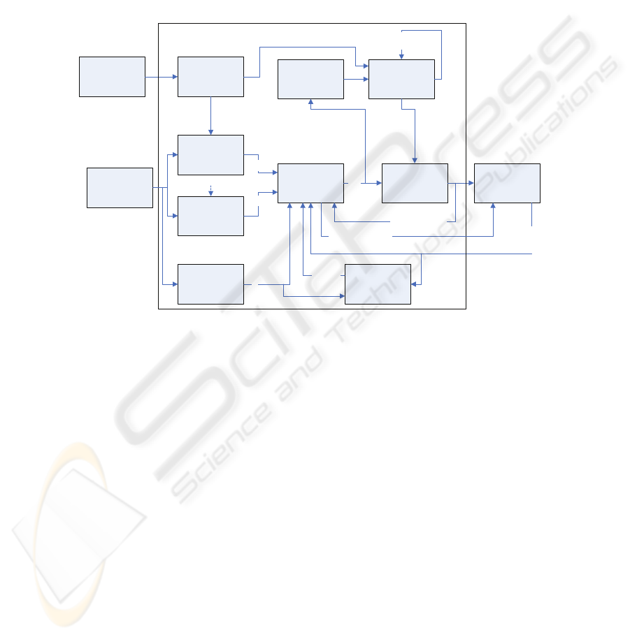
The proposed vision system is summarized in the block diagram shown in figure 1. It
considers object preceptors, a holistic characterization of the scenes, context
coherence filtering between current and past detections, encoder-based, visual-based
and filtered horizon information, objects characterization, situation (global) context,
and high-level tracking (estimation) for the detected objects’ poses.
2.1 Perceptors
Each object of interest has a specialized perceptor that detects and characterizes it.
For a detailed description of the perceptors used in our system, refer to [16]. The
output of a perceptor i at time step k is a candidate object
i
k
c , defined as:
()
,,,,,,
iii
kkk
T
ii iii
kk kkk
c
η
αησσ
=Σ
xy
xy
(1)
where
i
k
x is the relative pose of the object with respect to the robot,
i
k
Σ
x
is the
covariance matrix of
i
k
x ,
i
k
α
is the a priori probability of the detection, and (
i
k
y
,
i
k
η
)
and (
i
k
σ
y
,
i
k
η
σ
) are the horizon position and angle, and their corresponding tolerances
(see explanation in section 2.5.2).
2.2 Image Holistic Characterization
As stated in [6], a single glance to a complex, real world scene is enough for an
observer to comprehend a variety of perceptual and semantic information. There are
several works that use different alternatives of representations of the global
138
information contained in an image (e.g. spatial frequency orientations and scales,
color, texture density). We believe that some of those representations can be
complementary, and that the selection of a subset of them can be done taking into
account the kind of application for which the vision system is designed. For a general
mobile robot vision system it is expected that the image characterization be invariant
to lighting conditions, rotations, translations, and image distortions such as blur.
Neck
Encoders
Camera
Encoders
Horizon
Perceptor 1
Filtered
Horizon
Objects Final
Characterization
Context Filter
c
1
k
Filtered Horizon
in k-1
{d
i
k
}
HL-Tracking
High Level
Tracked Objects
in k-1 {h
i
k-1
}
Detected Objects
in k-1, {d
i
k-1
}
Perceptor N
c
N
k
Visual
Horizon
Calculation
Candidates
Detected
Objects
Image Holistic
Characterization
a
k
High Level
Objects Coherence
in k-1 {r
i
k-1
}
Situation
Determination
Situation
s
k
Fig. 1. Block diagram of the proposed general vision system for a mobile robot with a mobile
camera.
2.3 Situation Determination
This stage intends to determine the situation in which the observer is involved. We
propose that, for solving this task, it is necessary to consider several consecutive
images, in an incremental process. This is inspired in the hypothesis that human visual
system needs a short-term memory to adequately interpret images [11]. What we call
as a situation goes from the kind of environment the robot is immersed in (natural,
artificial), passing through the determination of the specific place where the robot is
(inside room X, inside building Y), to the specific task that the robot is carrying out
(crossing the street, raising the stairs, in a soccer game, etc.). A situation is not
expected to change suddenly. Instead, one expects to have transition probabilities
between situations given the observations and the observer odometry. We think that
the situation state can be modeled as a Markov process, where, for each known
situation, there is a transition probability to other situation. The transition probabilities
are conditioned on the last coherent observations (HL-tracking module), and the
current image holistic characterization.
139

2.4 H-L Tracking
The high-level (H-L) tracking stage is intended to maintain information about the
objects detected in the past, although they are currently not observed (for instance, in
any moment you have an estimation of the relative position of the objects that are
behind you). This tracking stage is basically a state estimator for each object of
interest, where the state to be estimated, for fixed objects, is the relative pose
i
k
x of
the object with respect to the robot. For mobile objects, the relative velocity
i
k
v
may
be added to the state vector. Every time the robot moves, a new state is predicted for
each object been tracked. On the other hand, every time an object is detected, its state
estimation
i
k
x and covariance
i
k
Σ
x
are corrected based in the new observation. This
module can be implemented using standard state estimation algorithms as Kalman or
Particle Filters.
2.5 Context Filter
In this module context information is employed for filtering candidate objects. All
candidate objects must be coherent between them, and also they must be coherent
with the current situation, and the holistic image characterization. Moreover,
candidate objects must be coherent with their past detections (detected objects in the
previous time step), and their current pose estimation. Thus, the context of a candidate
object consists of all the information obtained from the current and past images,
excepting the information obtained from the candidate itself.
2.5.1 Objects Coherence
Let
i
k
K be the vector of N candidates from the image at time k, excepting
i
k
c ,
k
D the
vector of
N detections obtained by applying the context coherence filter to the
elements of
k
C ,
k
H the vector of high-level objects poses estimations, a
k
the current
image holistic characterization, and
s
k
the current situation. Then, the context vector
i
k
^ of
i
k
c is defined as:
()
11
,,,,
T
iiTTT
kkkkkk
as
−−
= KD H^
(2)
Every element
i
k
j
⎡⎤
⎣⎦
^
of the context vector has an associated weight
,
i
kj
ω
that
corresponds to the probability of
i
k
j
⎡
⎤
⎣
⎦
^
. The context weight vector is defined as:
() ()
(
)
(
)
,
11 ,1 ,
,,, , ,...,
TT
iiTTT ii
kkkk k k k kL
pa ps
ωω
−−
==
CD H
ΩΩΩΩ
(3)
with
31LN=+, and
140

()
,1 11
,..,,,..,
T
iiiN
kkkkk
ααα α
−+
=
C
Ω ;
(
)
1
111
,..,
T
N
kkk
pp
−−−
=
D
Ω ;
(
)
1
111
,..,
T
N
kkk
ββ
−−−
=
H
Ω
(4)
Here,
i
k
α
,
i
k
p and
i
k
β
are respectively the a priori probability of the candidate
i
k
c ,
the a posteriori probability of the detection
i
k
d , and the accumulated probability of the
tracked object
i
k
h . Then, we define the coherence of
i
k
c as:
()
(
)
(
)
(
)
(
)
,
11
,
11
||
|
LL
ii i ii i
kk k kk kj
jj j
jj
iii
kkk
LL
ii
kkj
j
jj
pc p pc
qpc
p
ω
ω
==
==
⎡⎤ ⎡⎤ ⎡⎤
⎣⎦ ⎣⎦ ⎣⎦
== =
⎡⎤
⎣⎦
∑∑
∑∑
^^ ^
^
^
(5)
The a posteriori probability of
i
k
c is then defined as:
(
)
,
1
,
1
|
L
ii i
kk kj
j
j
iiii
kkkk
L
i
kj
j
pc
pq
ω
αα
ω
=
=
⎡⎤
⎣⎦
==
∑
∑
^
(6)
We shall then calculate the probabilities
(
)
|
ii
kk
j
pc
⎡
⎤
⎣
⎦
^
.
2.5.2 Relationships between Physical Objects
There are four kind of relationships that can be checked between physical objects.
The first two must be checked between candidates belonging to the same image, or at
most between candidates of very close images, when the camera’s pose change is
bounded. The last two may be checked between candidates or objects of different
images, considering the camera’s pose change between images.
Horizontal Position Alignment
. As we said before, most of the objects in the real
world are supported on ground. This, plus the knowledge of the height of the object,
gives us information about a region of the object that is likely to be at the same
altitude as the camera. For each candidate
i
k
c
, we will call the center of this region,
i
k
y , the horizontal point of the candidate, and its tolerance will be noted
i
k
σ
y
.
Horizontal points of correct candidates are supposed to be part of a line, the visual
horizon.
Horizon Orientation Alignment. Another quality of several objects is their
almost fixed orientation with respect to a vertical axis. Using this quality, it is
possible to find a horizon angle that is coherent with the orientation of the object in
the image. For each candidate
i
k
c , we will call this angle,
i
k
η
, the horizontal angle of
the candidate, and its tolerance will be noted
i
k
η
σ
. Horizontal angles of correct
candidates must have similar values, and furthermore, they are expected to be similar
to the angle of the visual horizontal obtained from the horizontal points.
141

Relative Position or Distance Limits. In some specific situations, objects are part
of a fixed layout. The robot may know this layout a priori from two different sources:
been previously taught about it, or learning it from observations, as in SLAM. In both
cases, the robot can check if the relative position between two objects, or at least their
distances (when objects has radial symmetry), is maintained.
Speed and Acceleration Limits. Even between mobile objects, it is possible to
check their relative speed and acceleration limits. Of course, it is necessary to have a
previous knowledge of those limits related with the objects identity.
2.5.3 High Level Tracked Objects Maintenance
When an object is detected and it is not been tracked, the HL-Tracking module creates
a new state estimator for it, and initializes it whit all the values coming from the
detection process. In particular, the coherence is initialized with the coherence
obtained by the candidate that generated the detection. However, as the robot moves,
odometry errors accumulate and high-level estimations become unreliable. If a set of
high-level estimations is self-coherent, but moves too far from real poses of tracked
objects, then all the new observations may become incoherent and be rejected. To
avoid this kind of situations, high-level estimations are also evaluated in the
coherence filter. In order to inhibit the self-confirmation of an obsolete set of
estimations, the coherence
i
k
r
is only checked with respect to the current observations,
but it is smoothed to avoid a single outlier observation discarding all the objects been
tracked. Thus, the coherence of a tracked object is updated using:
()
()
1
1
1
|
1
N
ij j
kk k
j
ii
kk
N
j
k
j
ph c
rr
α
λλ
α
=
−
=
=+−
∑
∑
(7)
where
λ
is a smoothing factor. As the coherence is recalculated, the a posteriori score
shall be also recalculated according to
iii
kkk
r
β
α
= . The a priori score is kept in the
same value obtained from the object’s last perception.
2.6 Encoders Horizon, Visual Horizon, Filtered Horizon and Objects Final
Characterization
In the Encoders Horizon module, the horizon line in each image is estimated using the
information from the neck encoders, and an estimation of the body inclination
obtained from either encoders or accelerometers. However, depending on the robot
architecture, both measurements used to calculate the encoders’ horizon are noisy and
can yield a very poor estimate of the horizon line. This affects the characterization of
some objects, for example, when measuring the distance to certain pixel which is
known to be at the ground, using its elevation angle. To solve this problem, we have
implemented a
Visual Horizon module. In this module, information from detected
objects is used to calculate a consensual horizon. The horizon line can be defined with
142

two parameters: its distance to the image center and its angle with respect to the rows
direction of the image.
Even when no visual object is detected, the previously computed horizon and the
changes of neck-encoders’ measurements are used to predict a final horizon in the
Filtered Horizon module. Afterwards, in the Objects Final Characterization module
objects relative poses are recalculated using the filtered horizon.
3 Detection of Static Objects in the RoboCup 4L League
We apply the proposed vision system in the RoboCup Four Legged League
environment (see description in [14]). In a Four Legged League soccer field, there are
many objects that have spatial relationships between them, and defined temporal
behaviors. These objects are goals, beacons, a ball, robots, and field lines. Some of
the objects are static and others are moving. Goals, beacons and field lines detection
is essential for the robot self-localization in the field, while ball and robots detection
is necessary for correctly playing soccer. Static objects in the field (beacons, goals
and field lines) are part of a fixed and previously known 3D layout. Thus, it is
possible to use several of the proposed relationships between objects to calculate a
candidate’s coherence. For this reasons we choose as a first application of our vision
system, the detection of static objects in the RoboCup Four Legged League domain.
Beacons have a radial symmetry. Detecting goals rotation with respect to the
camera is difficult because occlusions may change the ratio between the goal’s height
and width. For that reason it is not possible to determine the relative position of one of
these objects relative to other. Nevertheless we are able to use distances between them
and laterality. Laterality information comes from the fact that the robot is always
moving in an area that is surrounded by the fixed objects. For that reason, it is always
possible to determine, for any pair of candidates, which of them should be to the right
of the other. Then, depending on the kind of information that
i
k
j
⎡
⎤
⎣
⎦
^ represents,
(
)
|
ii
kk
j
pc
⎡⎤
⎣⎦
^
is calculated as:
()
(
)
(
)
(
)
||||
ij ij ij ij
k k Hor k k Lat k k Dist k k
pcc p ccp ccp cc=
(8)
()
(
)
(
)
(
)
1111
||||
ij ij ij ij
kk Horkk Latkk Distkk
pcd p cd p cd p cd
−−−−
=
(9)
()
(
)
(
)
111
|||
ij ij ij
k k Latk k Distk k
pc h p c h p c h
−−−
=
(10)
(
)
(
)
|,|
iii
kk kkk
pc a p a
η
= y
(11)
We have not yet implemented the use of s
k
, as our vision system has been tested in
one single application.
The horizontal coherence between two candidates is approximated using a
triangular function:
143

()
(
)
(
)
,,
,,
|, ,
ij ji
kk
ij ij ji
Hor k k k k
pcc tri tri
ηη
ησ ησ
ΔΔ
=Δ Δ
(12)
()
1
,
0
x
x
tri x
otherwise
σ
σ
σ
Δ
⎧
−Δ<
⎪
Δ=
⎨
⎪
⎩
(13)
with
,,ij i ij
kkk
ηηη
Δ=− ;
(
)
,,ij ji i j
kk kk
ηη
== −
yy
(
(14)
and
,,
1
tan
ij
k
k
ij ji i j
k
kk k
ij
kk
η
ηη η
σσ
σσσσ
−
ΔΔ
+
⎛⎞
⎜⎟
==++
⎜⎟
−
⎝⎠
y
y
yy
(15)
Similarly, the calculation of
(
)
|
ij
H
or k k
pcd is totally analogous with only two
differences:
j
k
y
and
j
k
η
are modified using the encoders information, and the
tolerances
j
k
η
σ
and
j
k
σ
y
are increased to meet the uncertainty generated by the
possible camera and robot movements. The lateral coherences,
()
|
ij
L
at k k
pcc,
()
|
ij
L
at k k
pcd and
()
|
ij
L
at k k
pch, are defined as binary functions, which are equal to 1
if the lateral relation between
i
k
c
and
j
k
c
,
j
k
d
or
j
k
h
, is the expected one, and 0
otherwise. The distance coherence, p
Dist
, is also approximated using a triangular
function:
()
(
)
,
,
|,
ij
k
ij ij
Dist k k k
x
pcc tri
σ
Δ
=Δx
(16)
with
,ij i j
kkk
Δ=−xxx, and
i
k
x ,
j
k
x been the relative detected positions of
i
k
c and
j
k
c
respectively. The calculation of
(
)
|
ij
D
ist k k
pcd
and
(
)
|
ij
D
ist k k
pch
is analogous. The
tolerance
,ij
k
x
σ
Δ
is calculated as a function of the covariance matrices
i
k
Σ
x
and
j
k
Σ
x
.
The global measure of the image we selected for this application is similar to that
of Color Shapes [15], with the difference that we make histograms of color classes,
after a color segmentation stage. We divided the image in cells of 16x16 pixels. The
probability
()
,|
ii
kk k
pa
η
y is approximated by:
()
(
)
(
)
inf, sup,
,|
ii i i
kk k k k
p a pa pa
η
=y
(17)
where
inf,
i
k
a
and
sup,
i
k
a
are respectively the inferior and superior histograms of the
image. The superior (inferior) histogram counts all bins of cells being over (below)
the horizon line. The probabilities
(
)
inf,
i
k
pa and
(
)
sup,
i
k
pa are associated to the
144

likelihoods of
inf,
i
k
a and
sup,
i
k
a been obtained from the corresponding regions of the
image:
()
(
)
()()
inf, inf inf
inf,
inf, inf inf inf,
,,
1
,, ,,
i
k
i
k
ii
kk
innov a a
pa
innov a a innov a a
=−
+
A
AA
(18)
()
(
)
()()
sup, sup sup
sup,
sup, sup sup sup,
,,
1
,, ,,
i
k
i
k
ii
kk
innov a a
pa
innov a a innov a a
=−
+
A
AA
(19)
with
()()()
,,
T
innov =− −zzZ z z Zz z .
This has the implicit assumption that
inf,
i
k
a and
sup,
i
k
a has different PDF’s, which in
our application is valid (for example, it is more likely to find green below the
horizon). The parameters
sup sup inf inf
,,,,,aaaAAA correspond to the means and
covariances over and below the horizon and of the whole image. They are obtained
from a training set of approximately 200 images captured from different positions in
the field.
(
)
k
pa is assumed to be Gaussian with mean a and covariance A .
4 Experimental Results
We have tested our vision system using real video sequences obtained by an AIBO
Robot inside a RoboCup four legged soccer field. The detection rates were measured
in different situations having different quantities of false objects. False objects are
objects that resemble to the actual ones, and that the color-based vision system is not
able to correctly distinguish. For example, a spectator wearing a yellow shirt is a false
yellow goal. Even objects having the same appearance but put in a different place are
false objects. For example, a yellow goal of a neighbor field is a false yellow goal.
For illustrating the operation of the system, Fig. 2 shows some example images
where context becomes relevant to discriminate between false and true objects. Fig. 2
shows two examples of a posteriori probabilities obtained by different false and true
objects. Fig 2.a. contains a false beacon (p = 0.10), a false goal (p = 0.01), a true
beacon (p = 0.38) and a true goal (p = 0.48). Fig 2.b. contains three beacons of which
two are true (p = 0.43, 0.58) and one is false (p = 0.00). Even when the shown false
objects are not a priori differentiable (they are all true objects placed in wrong places),
and thus, a priori probabilities are the same for all objects (p = 1.00), context is
helpful to differentiate a posteriori probabilities of true and false objects.
145
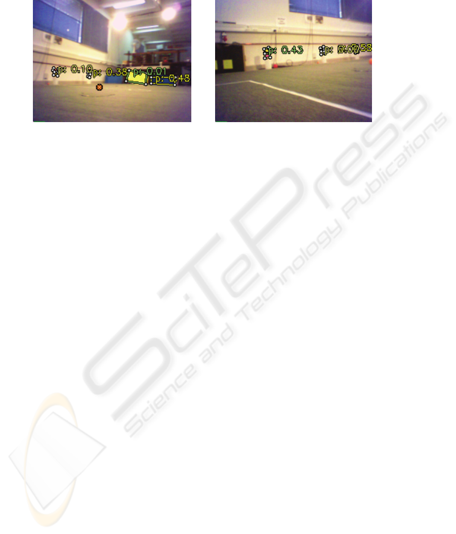
(a) (b)
Fig. 2. Some examples of a posteriori probabilities for true and false objects.
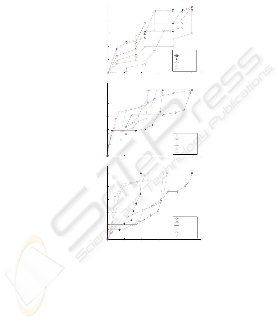
With the purpose of evaluating the performance of the system, the different ROC
curves in Fig. 3 compare the use of the different scores of the object to detect it; a
priori (with no use of context), a posteriori (using of all the context information), and
partial scores obtained from the consideration of one single type of context: current
(objects detected in the current image), HL-Tracking, last (objects detected in the last
image), and global (global measurements). In the situation of Fig 3.a, false objects
present were “natural” objects, like the cyan blinds and some other objects of our
laboratory, these objects appear in approximately 20% of the frames. In Fig 3.b, two
more aggressive objects were added: two false goals over the ground plane and in the
border of the field. In Fig 3.c, two additional false objects were added (over those of
Fig 3.b): two false beacons over the ground plane, in the border of the field.
These noisy situations may appear as artificially overexposed to false objects, but
they are neither very different to the actual situations observed in RoboCup games
with several spectators in the border of the field nor more noisy than real
environments situations. Note how the a priori and a posteriori ROC curves evolve as
the quantity of noise is increased. When facing situations with a low quantity of false
objects, the use of context appears as no improving the performance of the system
(Fig 3.a). However, as the quantity of false objects grows, the use of context increases
noticeably the detection rate for a given false negative rate (Fig 3.b, 3.c).
The results presented correspond to sequences obtained with the robot camera
moving, and the robot either standing or moving.
5 Conclusions
We have presented a general context based vision system for a mobile robot having a
mobile camera. The use of spatiotemporal context is intended to make the vision
system robust to noise and high performing in the task of object detection.
146
(a)
0 0.2 0.4 0.6 0.8 1
0
0.2
0.4
0.6
0.8
1
false detection rate
true detection rate
A priori
A posteriori
Current
HLTracking
Last
Global
(b)
0 0.2 0.4 0.6 0.8 1
0
0.2
0.4
0.6
0.8
1
false detection rate
true detection rate
A priori
A posteriori
Current
HLTracking
Last
Global
(c)
0 0.2 0.4 0.6 0.8 1
0
0.2
0.4
0.6
0.8
1
false detection rate
true detection rate
A priori
A posteriori
Current
HLTracking
Last
Global
Fig. 3. ROC Curves with low (a), medium (b) and high (c) quantity of noise.
We have first applied our vision system to detect static objects in the RoboCup
Four Legged League domain, and preliminary experimental results are presented.
Experimental results confirm that the use of spatiotemporal context is of great help
to improve the performance obtained when facing the task of object detection in a
noisy environment. We are working in obtaining more experimental results to provide
a better characterization of the system. The existing results encourage us to continue
developing our system and to test it in other applications, where different physical
objects and lighting conditions may exist and thus a situation determination stage and
different perceptors and global measures should be considered.
147

Acknowledgements
“This research was partially supported by FONDECYT (Chile) under Project Number
1061158”.
References
1. A. Torralba, P. Sinha. “On Statistical Context Priming for Object Detection”. International
Conference on Computer Vision, 2001.
2. A. Torralba. “Modeling global scene factors in attention”. JOSA - A, vol. 20, 7, 2003.
3. D. Cameron and N. Barnes. “Knowledge-based autonomous dynamic color calibration”.
The Seventh International RoboCup Symposium, 2003.
4. A. Oliva, A. Torralba, A. Guerin-Dugue, and J. Herault. “Global semantic classification of
scenes using power spectrum templates”. Proceedings of The Challenge of Image Retrieval
(CIR99), Springer Verlag BCS Electronic Workshops in Computing series, Newcastle,
UK., 1999.
5. M. Jüngel, J. Hoffmann and M. Lötzsch. “A real time auto adjusting vision system for
robotic soccer”. The Seventh International RoboCup Symposium, 2003.
6. A. Oliva. “Gist of the Scene”. Neurobiology of Attention. Elsevier, San Diego, CA, pp. 251-
256. 2003.
7. S. Foucher, V. Gouaillier and L. Gagnon. “Global semantic classification of scenes using
ridgelet transform”. Human Vision and Electronic Imaging IX. Proceedings of the SPIE,
Volume 5292, pp. 402-413. 2004.
8. A. Torralba and A. Oliva, “Statistics of Natural Image Categories”. Network: Computation
in Neural Systems, No 14, August, pp. 391-412, 2003.
9. L. Spillman and J. Werner (Eds.), Visual Perception: The Neurophysiological Foundations,
Academic Press, 1990.
10. A. Oliva, and A. Torralba. “Modeling the Shape of the Scene: A Holistic Representation of
the Spatial Envelope”. International Journal of Computer Vision, Vol. 42, No. 3, pp. 145-
175. 2001.
11. Potter, M. C., Staub, A., Rado, J., & O'Connor, D. H. “Recognition memory for briefly
presented pictures: The time course of rapid forgetting”. Journal of Experimental
Psychology. Human Perception and Performance, 28, pp. 1163–1175. 2002.
12. Strat, T. “Employing contextual information in computer vision”. Proceedings of DARPA
Image Understanding Workshop. 1993.
13. J. Ruiz-del-Solar and R. Verschae, “Skin Detection using Neighborhood Information”.
Proc. 6th Int. Conf. on Face and Gesture Recognition – FG 2004, 463 – 468, Seoul, Korea,
May 2004.
14.RoboCup Technical Comitee, “RoboCup Four-Legged League Rule Book”.
http://www.tzi.de/4legged/bin/view/Website/WebHome. 2006.
15. R. Stehling, M. Nascimento, and A. Falcao. “On ‘Shapes’ of Colors for Content-Based
Image Retrieval”. Proceedings of the International Workshop on Multimedia Information
Retrieval, pp 171-174. 2000.
16. Zagal, J.C., Ruiz-del-Solar, J., Guerrero, P. and Palma R. (2004). “Evolving Visual Object
Recognition for Legged Robots”. Lecture Notes in Computer Science 3020 (RoboCup
2003), Springer, 181-191.
148
