
A PRECISE APPROACH FOR RECOVERING POSES OF DISTAL
LOCKING HOLES FROM SINGLE CALIBRATED X-RAY
IMAGE FOR COMPUTER-ASSISTED INTRAMEDULLARY
NAILING OF FEMORAL SHAFT FRACTURES
Guoyan Zheng and Xuan Zhang
MEM Research Center – ISTB, University of Bern, Stauffacherstrasse 78, CH-3014, Bern, Switzerland
Keywords: Model-based fitting, parameter decomposition, computer-assisted intramedullary nailing.
Abstract: One of the most difficult steps of intramedullary nailing of femoral shaft fractures is distal locking – the
insertion of distal transverse interlocking screws, for which it is necessary to know the position and
orientation of the distal locking holes of the intramedullary nail. This paper presents a precise approach for
solving this problem using single calibrated X-ray image via parameter decomposition. The problem is
formulated as a model-based optimal fitting process, where the to-be-optimized parameters are decomposed
into two sets: (a) the angle between the nail axis and its projection on the imaging plane, and (b) the
translation and rotation of the geometrical models of the distal locking holes around the nail axis. By using a
hybrid optimization technique coupling an evolutionary strategy and a local search algorithm to find the
optimal values of the latter set of parameters for any given value of the former one, we reduce the multiple-
dimensional model-based optimal fitting problem to a one-dimensional search along a finite interval. We
report the results of our in vitro experiments, which demonstrate that the accuracy of our approach is
adequate for successful distal locking of intramedullary nails.
1 INTRODUCTION
It has been recognized that one of the most difficult
steps of intramedullary nailing of femoral shaft
fractures is distal locking – the insertion of distal
interlocking screws, for which it is necessary to
know the positions and orientations of the distal
locking holes (DLHs) of the intramedullary nail
(IMN). Complicating the process of locating and
inserting the distal interlocking screw is the nail
deformation with insertion. It has been reported that
deformation occurs in several planes due to medial-
lateral (ML) and anterior-posterior (AP) flexion of
the distal nail after it has been inserted. Using a
magnetic tracking system in a cadaveric study,
Krettek et al. (1998) reported following deformation
measurement results for small-diameter nails and
large-diameter nails, respectively: lateral translations
of 18.1
±
10.0 mm and 21.5
±
7.9 mm, dorsal
translations of -3.1
± 4.3 mm and 0.4 ± 9.8 mm,
and rotation about the longitudinal axes of -0.1
±
0.2 degrees and 10.0
± 3.1 degrees. The reason for
the wide variations of the insertion-related femoral
nail deformation is due to the fact that the nail has to
deform to the shape of the medullary canal upon
insertion. The shape of the canal varies widely from
person to person. It is not possible to predict how the
nail will deform accordingly. Therefore, it is very
difficult, to determine what the resultant locations
and orientations of the DLHs will be relative to their
initial position before it is deformed. The surgeon
depends heavily on intra-operative X-ray means in a
conventional surgical procedure for providing
precise locations and orientations of the DLHs. It
requires positioning the axis of the fluoroscope
perpendicular to the locking holes so that these holes
appear perfectly circular in the images. This is
achieved through a trial-and-error method and
requires long time X-ray exposure for both the
surgeon and patient. It has been reported that the
surgeon’s direct exposure to radiation for each
conventional surgical procedure was 3 – 30 min, of
which 31% - 51% was used for distal locking
(Sajeldal and Backe 1987).
The desire to target accurately with as little as
possible X-ray exposure has led to various attempts
120
Zheng G. and Zhang X. (2007).
A PRECISE APPROACH FOR RECOVERING POSES OF DISTAL LOCKING HOLES FROM SINGLE CALIBRATED X-RAY IMAGE FOR COMPUTER-
ASSISTED INTRAMEDULLARY NAILING OF FEMORAL SHAFT FRACTURES.
In Proceedings of the Second International Conference on Computer Vision Theor y and Applications, pages 120-127
DOI: 10.5220/0002066101200127
Copyright
c
SciTePress
to develop image-based methods for recovering the
positions and orientations of DLHs (Zhu et al. 2002,
Leloup et al. 2004, Yaniv and Joskowicz 2005).
These methods require either multiple calibrated
images or single image but with perfectly circular
holes in the image, which normally requires the X-
ray technician to use a try-and-move method several
times to achieve.
This paper presents a precise approach for
solving this problem using single calibrated
fluoroscopic image via parameter decomposition.
We do not ask for an image with perfectly circular
holes but we do put a constraint on its acquisition,
i.e., the reduced patient shaft should be roughly
parallel to the image intensifier (II) of the
fluoroscopy machine, which is much easier to be
achieved intraoperatively. We then formulate the
pose recovery of the DLHs as a model-based fitting
problem and decompose the to-be-optimized
parameters into two sets: (a) the angle between the
nail axis and its projection on the imaging plane, and
(b) the translation and rotation of the geometrical
models of the DLHs around the nail axis. By using a
hybrid optimization technique (Zheng et al. 2006)
coupling an evolutionary strategy and a local search
algorithm to find the optimal values of the latter set
of parameters for each give value of the former one,
we reduce the multiple-dimensional optimal fitting
problem to a one-dimensional search along a finite
interval.
The paper is organized as follows. Section 2
describes image calibration, geometrical models, and
preprocessing. In Section 3, we describe the
proposed approach in details. Section 4 presents our
in-vitro experimental results, followed by
conclusions in Section 5.
2 IMAGE CALIBRATION,
GEOMETRICAL MODEL AND
PREPROCESSING
2.1 Image Calibration
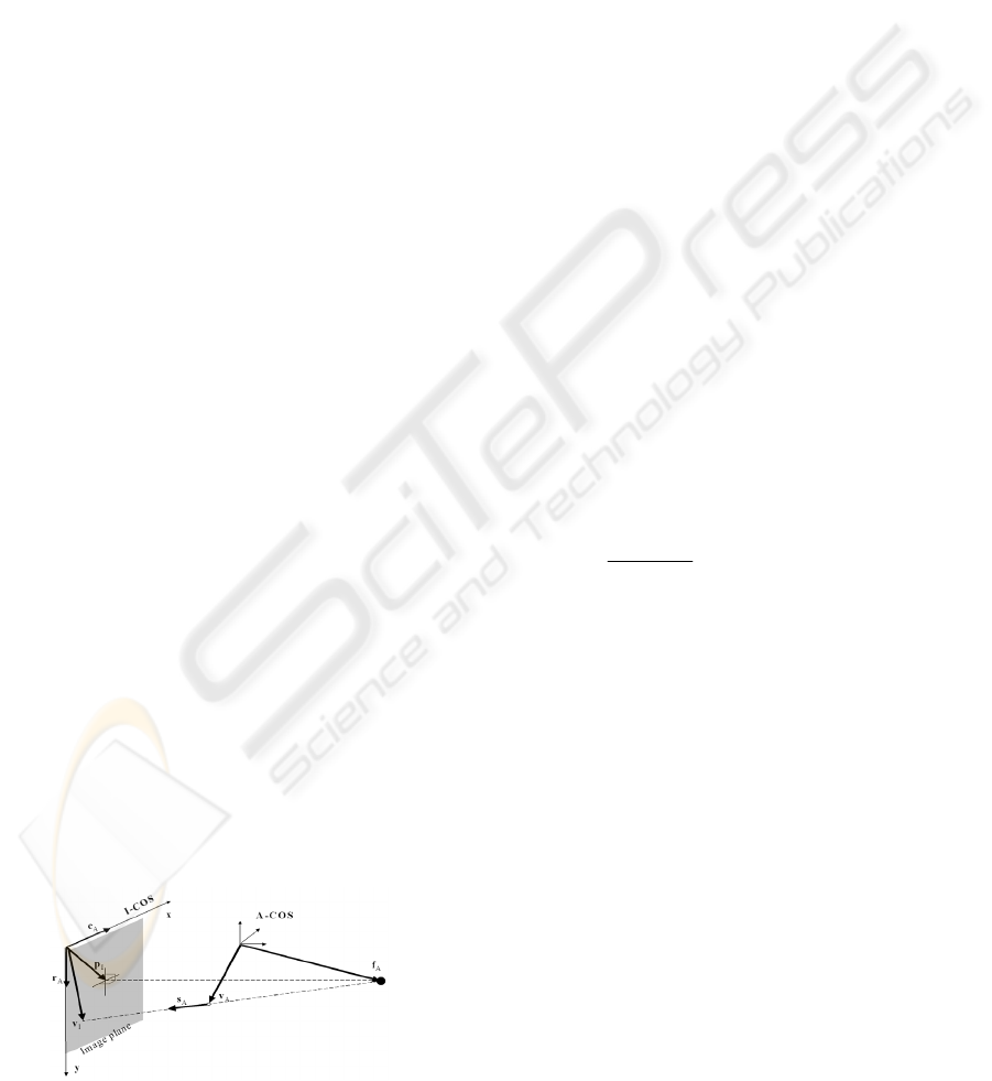
Figure 1: Weak-perspective pin-hole camera model.
In reality, the proximal fragment, the distal
fragment, and the nail may be treated as three rigid
bodies and registered independently. The rigid
transformations between these three rigid bodies can
be trivially obtained from a navigator such as an
optoelectronic tracker, a magnetic tracker, or even a
medical robot (Langlotz and Nolte 2004). As this is
not our focus in this paper, here we assume that the
fractured femur has already been reduced and the
proximal fragment and distal fragment are kept fixed
relative to each other at the time of image
acquisition. We also assume that the nail has been
inserted till the distal end of the femur and has been
locked proximally by screw so that the complete
femur and the nail can be treated as one rigid body.
A local coordinate system (COS) is established on
this rigid body through a so-called dynamic
reference base (DRB) technique (Nolte et al. 1995).
In the following description, let’s denote this patient
COS as
COS
A
−
. All computations are done in this
reference COS.
To relate a pixel in the two-dimensional (2D)
projection image to
COS
A
−
, the acquired image
has to be calibrated for physical projection
properties and be corrected for various types of
distortion. We have chosen a weak-perspective pin-
hole camera model as shown in Figure 1 for
modeling the C-arm projection (Gremban et al.
1988). Using such a camera model, a 2D pixel V
I
is
related to a three-dimensional (3D) point V
A
by
following equations:
⎥
⎥
⎥
⎥
⎦
⎤
⎢
⎢
⎢
⎢
⎣
⎡
⎥
⎥
⎥
⎦
⎤
⎢
⎢
⎢
⎣
⎡
=
⎥
⎥
⎥
⎦
⎤
⎢
⎢
⎢
⎣
⎡
−
−
=
1
S
S
S
1000
p
pccc
1
V
V
;
||fV||
)f(V
S
z
y
x
yzyx
xzyx
y
x
A,
A,
A,
I,A,A,A,
I,A,A,A,
I,
I,
AA
AA
A
rrr
(1)
where
||||
⋅
means to calculate the length of a vector
and the vectors f
A
, r
A
, c
A
and p
I
represent the
position of focal point, the vector along image row
increasing direction, the vector along image column
increasing direction, and the 2D position of piercing
point, respectively. They are projection parameters
used to describe the projection properties of the C-
arm and need to be calibrated preoperatively
Eq. (1) can be used for both forward and
backward projections. For example, if we want to
calculate the direction
A
S of the forward projection
ray of an image point V
I
, an additional constraint
1
A
=
||S|| can be used together with Eq. (1) to solve
for it. The forward projection ray of point V
I
is
defined by the focal point and the direction.
PRECISE APPROACH FOR RECOVERING POSES OF DISTAL LOCKING HOLES FROM SINGLE CALIBRATED
X-RAY IMAGE FOR COMPUTER-ASSISTED INTRAMEDULLARY NAILING OF FEMORAL SHAFT FRACTURES
121
The position of the imaging plane in
COS
A
−
and the focal length in our camera model is
implicitly determined using the calibrated focal
point f
A
and the vectors r
A
and c
A
. Any 2D image
point V
I
corresponds to a 3D spatial point I
A
in this
imaging plane, which is the intersection between its
forward projection ray and this plane.
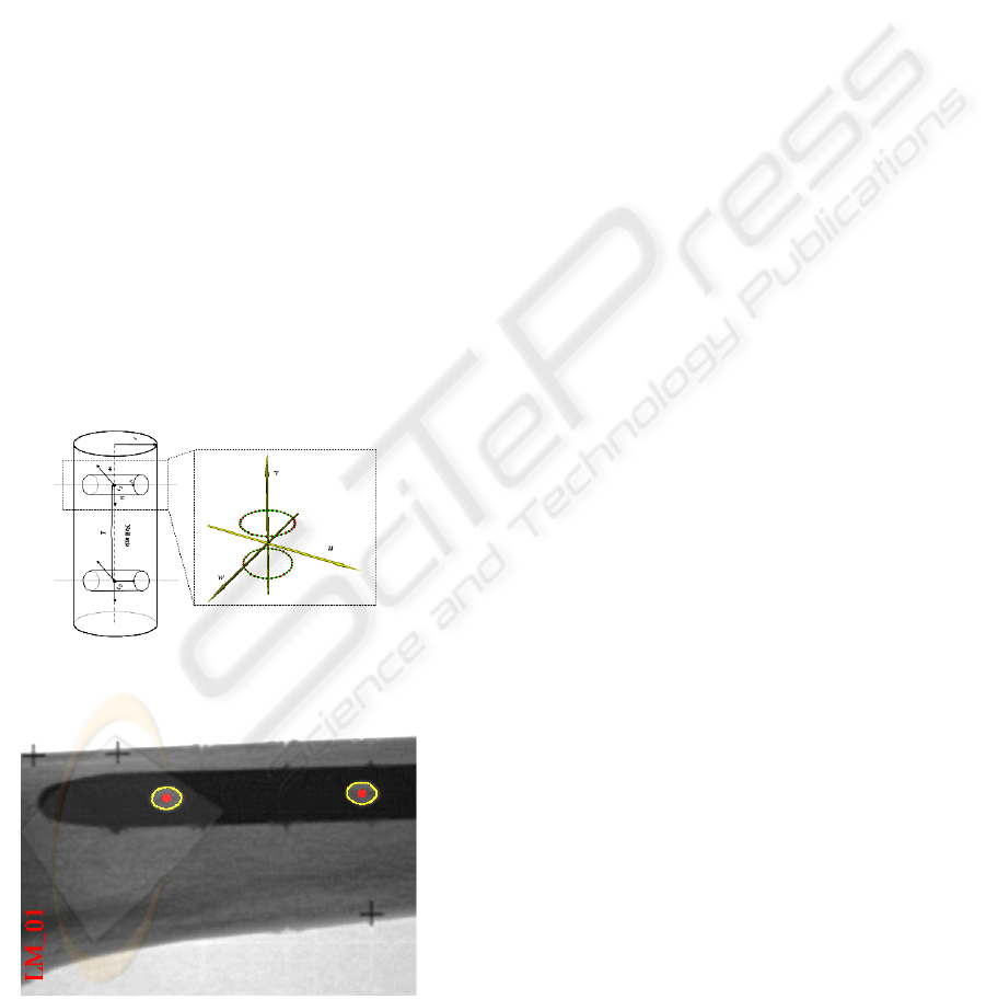
2.2 Geometrical Models
The distal part of IMN containing the two DLHs,
which is what we are interested in, is modeled as a
cylinder (Figure 2, left). The distance L between the
centers of the two DLHs can be accurately extracted
from its product information. The geometrical model
of each DLH is represented by two circles as shown
by Figure 2, right, and is used later to simulate X-ray
projection of the DLH model.
To obtain the coordinates of those points
(visualized as red dots in Figure 2, right) used to
describe the model of the DLH, a local COS
uvwC'
is established by taking the intersection point C (it is
also called the center of the DLH) between the axis
of the DLH and the axis of the IMN as the origin,
the axis of the IMN as the u axis, and the axis of the
DLH as the
v
axis (see Figure 2 for details).
Figure 2: The geometrical model of the distal part of the
IMN (left) and the geometrical model of the DLH (right).
Figure 3: Feature point detection. The detected projection
points (red dots) of the centers of both DLHs are displayed
together with the edge pixels of the DLHs (yellow).
The coordinates of those points expressed in this
local COS can be directly measured from the nail
using a caliber, thanks to the symmetrical property
of the DLH; or extracted from the engineering
drawings of the nail, if they are available.
2.3 Preprocessing
The task of the preprocessing is to determine the
projection points of the centers of the DLHs. To
extract these feature points from the image, Hough
transform (Jain and Schunk 1995) is used to find the
two mostly parallel edge lines of the projection of
the distal part of the IMN after applying a Canny
edge detector to the image. The projection of the
axis of the distal part of the IMN is considered as the
middle line between these two mostly parallel edge
lines. To determine those edge pixels belonging to
DLHs, the method reported in (Yaniv and Joskowicz
2005) is modified for our purpose. A parallelpiped
window, whose sizes are equal to the distance
between the detected edge lines, is swept along the
middle line to find two locations which contain the
maximum number of edge pixels and whose distance
is greater than a pre-selected distance threshold T
(e.g. the width of the window). The centroids of the
detected edge pixels in both locations are then
calculated. The projection of the center of each DLH
is then determined by finding the closest point on the
middle line to the associated centroid. An example
of feature point detection is shown in Figure 3.
3 THE PROPOSED APPROACH
3.1 Model-based Fitting for Pose
Recovery
Using above detected feature points, we can find
their corresponding spatial points on the imaging
plane. Let’s denote them as d
1
corresponding to the
projection point of the center C
1
of the distal DLH
(the DLH that is closer to the nail tip), and d
2
corresponding to the projection point of the center
C
2
of the proximal DLH, respectively, as shown in
Figure 4. These two points define a line in A-COS.
This line together with the focal point f defines a
plane where the axis of the distal part of the nail
should fall in. As we know the coordinates for point
f, d
1
, and d
2
, we can calculate three internal angles
ω
1
,
ω
2
, and
ω
3
of triangle fd
1
d
2
. Assume the angle
between the nail axis and its projection in the
VISAPP 2007 - International Conference on Computer Vision Theory and Applications
122

imaging plane is
α
, then the coordinates of the
centers of both DLHs are calculated as following:
)/,/(
)cos(
)sin(
)cos()sin(
)sin(
)sin(
||||
)(
;
||||
)(
22
2
3
32
2
3
2
1
2
2
22
1
1
11
ππα
αω
ω
ωαω
ω
αω
−∈
+⋅+
⋅+
⋅=
+
⋅=
−
−
⋅+=
−
−
⋅+=
where
LLL
LL
fd
f
d
LfC
fd
f
d
LfC
(2)
where L is the distance between the centers of two
DLHs. It can be measured or extracted from the
product information.
According to equation (2), the coordinates of
both centers only depends on the parameter
α
, so as
the direction of the nail axis (n
x
, n
y
, n
z
).
Assuming that the coordinates of the center C of
one of the DLHs is denoted as [C
x
, C
y
, C
z
]
T
, the
problem to estimate the pose of the DLH in A-COS
is now changed to find the rotation angle
α
, rotation
angle
θ
, and translation distance
δ
of the geometrical
model of the DLH along the nail axis [n
x
, n
y
, n
z
]
T
so
that the simulated X-ray projection of the DLH can
be fitted to its real X-ray projection (see Figure 4 for
details). This constrained transformation around the
parameterized nail axis could be described by a
33× rotation matrix ),,(
δ
θ
α
rot
⎥
⎥
⎥
⎦
⎤
⎢
⎢
⎢
⎣
⎡
+++−−−
−−+++−
+−−−++
)cos()()sin())cos(()sin())cos((
)sin())cos(()cos()()sin())cos((
)sin())cos(()sin())cos(()cos()(
θθθθθ
θθθθθ
θθθθθ
222
222
222
11
11
11
yxzxzyyzx
xzyzxyzyx
yzxzyxzyx
nnnnnnnnn
nnnnnnnnn
nnnnnnnnn
(3)
and a translational vector trans(α,
θ
,
δ
) = [t
x
, t
y
, t
z
]
T
:
⎪
⎪
⎪
⎪
⎪
⎪
⎪
⎩
⎪
⎪
⎪
⎪
⎪
⎪
⎪
⎨
⎧
⋅⋅+−⋅⋅+
++⋅⋅+−⋅⋅++⋅⋅+⋅
+⋅⋅++⋅⋅+⋅−+⋅⋅+=
⋅⋅+−⋅⋅+
++⋅⋅+−⋅⋅++⋅⋅+⋅
+⋅⋅++⋅⋅+⋅−+⋅⋅+=
⋅⋅+−⋅⋅+
++⋅⋅+−⋅⋅++⋅⋅+
⋅
+⋅⋅++⋅⋅+⋅−+⋅⋅+=
)sin())()((
)cos())()())()(((
))()(()()(
)sin())()((
)cos())()())()(((
))()(()()(
)sin())()((
)cos())()())()(((
))()(()()(
θδδ
θδδδ
δδδ
θδδ
θδδδ
δδδ
θδδ
θδδδ
δδδ
xyyzyxx
yxzzyyyxxxz
yyyxxxzyxzzz
zxxxzz
zxyyzzzxxxy
zzzxxxyzxyyy
yzzzyy
zyxxzzzyyyx
zzzyyyxzyxxx
nnCnnC
nnnCnnCnnCn
nnCnnCnnnnCt
nnCnnC
nnnCnnCnnCn
nnCnnCnnnnCt
nnCnnC
nnnCnnCnnCn
nnCnnCnnnnCt
22
22
22
22
22
22
(4)
The pose recovery problem can then be
formulated as an optimal model-based fitting:
2
||)),,(),,((||min
)(
}
*
,
*
,
*
{
δθαδθα
δθα
∑
+⋅−
=
i
iiCPj
transmrotPe
(5)
where {e
j
} are the detected edge pixels of the DLHs;
{m
i
} are the points used to describe the geometrical
models the DLHs; P(.) denotes the projection
operator; CP(.) denotes the action of finding the
closest edge pixel of the simulated projection point
into the image of a model point.
Figure 4: Schematic view of model-based fitting.
3.2 Parameter Estimation
Various techniques have been proposed for
estimating parameters for model-based fitting. Lowe
(1991) suggests to minimize the non-linear error
function on image domain, where the perpendicular
distance between projected model line and extracted
edge point will be minimized. The correspondence
between the model projection to image edge is found
by selecting the one who has the shortest
perpendicular distance. This strategy can lead to
some ambiguity in fitting process when part of the
model line has been occluded by structure of the
model itself. This problem was solved by Fua (1996)
through applying hidden algorithm to avoid this
pitfall. All these algorithms suffer from the facts that
they are easily to be trapped by a local minimum and
that the interpretation and initialization of model
parameter values have to be done by the operator,
which is not desirable for an intra-operative
application in a sterilized environment.
Parameter decomposition approach is a powerful
optimization method that tries to decompose a high-
dimensional problem into small, low-dimensional
components and estimate the parameters for each
component separately, thus reducing the
computational complexity. The general idea of
model decomposition for parameter estimation has
bee successfully applied in many domains, e.g.,
geometrical curve fitting (Jiang and Cheng 2005)
and Bayesian model learning (Neapolitan 2003).
According to our observation that the size of the
geometrical models of the DLHs (around 10 mm in
each dimension) is relatively small compared to the
focal length of the X-ray image (around 1000mm),
we decompose the control parameters in Eq. (5) into
two sets: (a) the angle
α
between the nail axis and its
projection in the imaging plane; and (b) the rotation
and translation distance of the geometrical models of
PRECISE APPROACH FOR RECOVERING POSES OF DISTAL LOCKING HOLES FROM SINGLE CALIBRATED
X-RAY IMAGE FOR COMPUTER-ASSISTED INTRAMEDULLARY NAILING OF FEMORAL SHAFT FRACTURES
123

the DLHs along the nail axis (
θ
,
δ
). Now the original
optimization problem can be re-formulated as:
)]||)),,(),,((||min(min[
)(
}
*
,
*
{
*
2
δθαδθα
δθ
α
∑
+⋅−
=
i
iiCPj
transmrotPe
(6)
Where the term in the square brackets simply means
the minimum sum of distance for a fixed
α
and all
possibilities of (
θ
,
δ
). The advantage of such
decomposition lies in the fact that the latter set of
variables can be calculated by using a hybrid
optimization technique coupling an evolutionary
strategy and an iterative closest projection point
algorithm (ICPP) as proposed in our previous work
(Zheng et al. 2006), which then reduces the original
multiple-dimensional optimization problem to a one-
dimensional search in a finite interval.
3.2.1 Initialization
Given a fixed
α
, we can estimate the positions of
both centers of DLHs and the orientation of the nail
axis. Then, the initial transformation between the
local COS of the geometrical model of the DLHs
and A-COS can be obtained by taking the estimated
center as the origin, the estimated nail axis as the u
axis, and the normal of the imaging plane as the v
axis. All points defined in the local COS of the
geometrical model of the DLH can then be
transformed to A-COS using this transformation. The
optimal values of the rotation
θ
and the translation δ
of the models along the nail axis can be optimally
estimated by fitting the geometrical models of the
DLHs to the image as by a hybrid optimization
technique as described below
3.2.2 The Iterative Closest Projection Point
(ICPP) Algorithm
Let’s denote E be a set of N
E
detected 2D edge
pixels
},...,,{
E
N
eee
21
of the DLH projection. Further
denote M
t-1
be a set of N
M
model
point
},...,,{
11
1
1
0
−−− t
M
N
tt
mmm at iteration step t-1. Now
in the iteration step t, we perform following steps:
Simulating X-ray projection: In this step, we
simulate the X-ray projection of the geometrical
models of the DLHs to remove invisible points. Let
1−t
P be a set of
P
N 2D projection points
},,,{
11
2
1
1
−−− t
P
N
tt
ppp L obtained by simulating X-ray
projection of 3D model into the image. Normally
MP
NN << . Thus, for each 2D projection point
1−t
i
p ,
we know its associated 3D model point
1−t
i
m
.
Find closest projection point: In this step, we try
to find the closest neighbor edge pixel
i
e of each 2D
model projection point
1−t
i
p .
Establishing 3D-2D correspondence: For each
2D matched pairs
),(
1−t
ii
pe , calculate the forward
projection ray
i
BP of the 2D edge pixel
i
e . Then for
the ray
i
BP , calculate a 3D point pair
),(
111 −−−
=
t
i
t
i
t
i
mbePP , where
1−t
i
be is a point on the
line
i
BP that is closest to the 3D model point
1−t
i
m
of
the model projection point
1−t
i
p .
Estimating pose: For all calculated 3D point
pairs
}{
)( 11 −−
=
t
i
t
PPPPS
, find an optimal local
solution of all pose parameters by minimizing
following disparity function
),(
)()( 11 −− tt
S
δθ
:
∑
−−−−−−−−
−−
−−
+⋅−=
i
ttt
i
ttt
i
tt
tt
tt
transmrotbeS
S
211111111
11
11
||),(),((||),(
),(minarg
)()()()()()(
)()(
}
*)(
,
*)(
{
δθδθδθ
δθ
δθ
(7)
where we drop the symbol
α
from the expressions,
as its value is fixed.
These steps are repeated until all pose
parameters are converged.
3.2.3 The Evolutionary Strategy
The ICPP algorithm can be regarded as a local
minimum search algorithm but we are trying to find
the global minimum of the disparity function that
may be well hidden among many poorer local
minima. In our approach, this is handled by
combining a conventional genetic algorithm
(Goldberg 1989) with the ICPP algorithm. The
genetic algorithm acts as a random generator for
possible parameter sets that solve the minimization
problem. All generated individual parameter set is
then fed through the ICPP algorithm before being
rated using the disparity function. Five best ones
become the parents of next generation. The
algorithm stops when the differences of the disparity
function values of all five best ones are smaller than
a pre-selected threshold.
VISAPP 2007 - International Conference on Computer Vision Theory and Applications
124

Figure 5: Optimization space of the nail tilt angle
α
.
3.2.4 Optimization of Parameter
α
We now convert a multiple-dimensional
optimization problem to a one-dimensional one,
where the parameter
α
can be optimized by a search
along a finite interval [-30
o
, +30
o
] (due to the
acquisition constraint that we put). A typical
optimization space of this parameter is shown in
Figure 5. It has a symmetrical shape and a clear
global optimum around the ground truth
α
=10.4
o
.
We could separate the optimization space into two
sub-intervals, i.e. [-30
o
, 0) and [0, 30
o
]. In each sub-
interval, the optimum of that sub-interval could be
easily found by a local search algorithm starting
from any initialization value. Actually, in all
experiments, we have simply initialized
α
by the
middle value of each sub-interval. The global
minimum is then found by taking the better one of
the two optima.
4 EXPERIMENTAL RESULTS
We designed and conducted two experiments to
analyze the accuracy and robustness of the proposed
approach. A SYNTHES® (STRATEC Medical,
Oberdorf, Switzerland) 9 mm solid titanium femoral
nail was used in our study. A Siemens ISO-C
3D
C-
arm (Siemens AG, Erlangen, Germany) was used to
acquire fluoroscopic images for our experiments.
In the first experiment, the nail was inserted into
a cadaveric human femur and was locked
proximally. The ground truth of the positions of the
DLHs was obtained after image acquisition by
inserting a custom-made steel rod through the hole
and then digitizing both top and bottom centers of
the rod using an optically trackable sharp pointer
(OPTOTRAK 3020, Northern Digital Inc, Waterloo,
Canada).
Three images acquired from different view
directions were used in our experiments, as shown in
Figure 6. For each image, we applied the proposed
approach ten times to estimate the poses of the
DLHs. The estimated results were compared to the
ground truth to compute the errors for each DLH,
which were defined as the angular difference
between the estimated hole axis and the one
obtained through pointer-based digitization, and the
positional difference of the entry point and its
ground truth along the plane perpendicular to the
hole axis (obtained by projecting the difference
vector into the plane perpendicular to the hole axis),
because the positional deviation along the hole axis
is not important for the task of insertion of distal
locking screw
In all studies, the poses of DLHs could be
automatically recovered. The angular and positional
errors are shown in Table I. Compared to ground
truths, the average angular error was found to be 1.0
o
(std=0.4
o
) and the average positional error along the
plane perpendicular to the hole axis was found to be
0.6 mm (std=0.4 mm).
In the second experiment, a test bench was
designed and implemented, which allowed rotation
and tilt of the test subject, as shown in Figure 7. The
nail was inserted tightly into the plastic bone and
was locked proximally. The plastic bone together
with the nail was then fixed to the test bench. A
dynamic reference base was fixed to the bone to
establish a local coordinate system. The ground
truths of the direction of the nail axis as well as the
positions of the centers of the DLHs and the
directions of the axes of the DLHs were obtained
from a registration-free 3D-navigation system [4]
using the SIREMOBIL ISO-C
3D
Carm.
The reference position (rotation = 0
o
, tilt = 0
o
)
was obtained using a try-and-move method until the
projections of both holes appeared perfectly circular.
We then tilted the test subject with an interval of 5
o
until 25
o
. At each tilted position, we rotated the test
subject with an interval of 5
o
until 25
o
, which results
in totally 6x6 = 36 configurations. For each
configuration (tilt, rotation), a lateral-medial image
was acquired.
We applied the present approach to these 36
images. For each image, we compared the estimated
results to the ground truths. We computed the
angular error of the estimated nail axis and the
angular errors of the estimated axes of the DLHs.
And to get a clear idea how the positional errors
were distributed, we decomposed the positional
errors along the three orthogonal directions, i.e., the
nail axis direction, the distal locking hole axis
PRECISE APPROACH FOR RECOVERING POSES OF DISTAL LOCKING HOLES FROM SINGLE CALIBRATED
X-RAY IMAGE FOR COMPUTER-ASSISTED INTRAMEDULLARY NAILING OF FEMORAL SHAFT FRACTURES
125

direction, and the cross product of the former two
directions.
It was found that angular errors in all
configurations except for two configurations (25
o
,
20
o
) and (25
o
, 25
o
) were smaller than 1.8
o
. The
positional errors along the distal locking hole axis
were bigger than those errors along other two
directions. When the tilt was smaller than 25
o
and
when the rotation was smaller than 25
o
, the average
angular error in estimating the nail axis was found to
be 0.5
o
(std=0.2
o
, max=1.2
o
), the average angular
error in estimating the axes of the DLHs was found
to be 0.7
o
(std=0.3
o
, max=1.5
o
), the average
positional error along the nail axis direction was
found to be 0.3 mm (std=0.4 mm, max=1.4 mm), the
average positional error along the distal locking hole
axis direction was found to be 1.3 mm (std=1.7 mm,
max=7.9 mm), and the average positional error
along the cross product direction was found to be 0.4
mm (std=0.5 mm, max=2.5 mm).
5 CONCLUSIONS
We have presented a novel variable decomposition
approach for automatic pose recovery of distal
locking holes from single calibrated fluoroscopic
image. Unlike previously introduced method (Yaniv
and Joskowicz 2005), our approach does not ask for
an image with perfectly circular holes. Our in vitro
experimental results demonstrate that the accuracy
of our approach is adequate for successful distal
locking of intramedullary nails.
REFERENCES
Krettek C., Mannβ J., Miclau T., et al. (1998) Deformation
of femoral nails with intramedullary insertion. J
Orthop Res, 16(5): 572 – 575.
Skjeldal S. and Backe S. (1987) Interlocking medullary
nails – radiation doses in distal targeting. Arch
Orthopaedic Trauma Surg, 106: 179 – 181.
Zhu Y., Phillips R., Griffiths J.G., et al. (2002) Recovery
of distal hole axis in intramedullary nail trajectory
planning. Proc Inst Mech Eng [H], 216(5): 323 – 332.
Leloup T., Schuind F., and Warzee N. (2004) Process for
the acquisition of information intended for the
insertion of a locking screw into an orifice of an
endomedullary device. European Patent Application
Number: 04447153.0.
Yaniv Z. and Joskowicz L. (2005) Precise robot-assisted
guide positioning for distal locking of intramedullary
nails. IEEE T Med Imaging, 24(5): 624 – 635.
Zheng G., et al. (2006) A robust and accurate two-stage
approach for automatic recovery of distal locking
holes in computer-assisted intramedullary nailing of
femoral shaft fractures. Submitted to IEEE T Med
Imaging.
Langlotz F. and Nolte L.-P. (2004) Technical approaches
to computer-assisted orthopedic surgery. Eur J
Trauma, 30(1): 1– 11.
Nolte L.-P., Visarius H., Arm E. et al. (1995) Computer-
aided fixation of spinal implants. J Image Guid Surg,
1: 88 – 93.
Gremban K.D., Thorpe C.E., Kanade T. (1988) Geometric
camera calibration using systems of linear equations.
In: Proceedings of IEEE conference on robotics and
automation, pp. 562-567.
Jain R., Kasturi R., and Schunk B. G. (1995) Machine
Vision. New York: McGraw-Hill.
Lowe F.G. (1991) Fitting parameterized three-dimensional
models to images. IEEE T Pattern Anal, 13(5): 441-
450.
Fua P. (1996) Model-based optimization: accurate and
consistent site modeling. The 18
th
Congress,
International Society for Photogrammetry and remote
sensing, Vienna, Austria, pp. 222-223.
Jiang X. and Cheng D.C. (2005) A novel parameter
decomposition approach to faithful fitting of quadric
surfaces. Pattern Recognition: 27
th
DAGM
Symposium, LNCS 3663, pp. 168-175
Neapolitan R.E. (2003), Learning Bayesian Networks. (1st
Ed) Prentice Hall
Goldberg D.E. (1989) Genetic algorithms in search,
optimization, and machine learning. Reading, MA,
Addison-Wesley.
VISAPP 2007 - International Conference on Computer Vision Theory and Applications
126
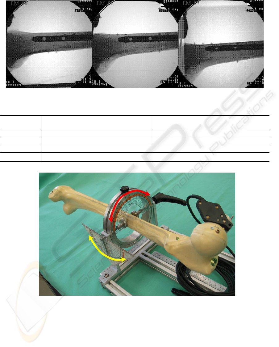
Figure 6: Three images used in our experiments. From left to right: LM_00, LM_01, and LM_02.
Table 1: Comparision results between the estimated poses of the distal locking holes and their associated ground truth.
Image Angular differences (
o
) Positional differences along the plane
perpendicular to the hole axis (mm)
LM_00 0.7 ± 0.3 0.2 ± 0.0
LM_01 0.9 ± 0.2 0.4 ± 0.1
LM_02 1.5 ± 0.2 1.1 ± 0.1
Overall 1.0 ± 0.4 0.6 ± 0.4
Figure 7: Test bench for evaluating the present approach.
Tilt
Rotation
PRECISE APPROACH FOR RECOVERING POSES OF DISTAL LOCKING HOLES FROM SINGLE CALIBRATED
X-RAY IMAGE FOR COMPUTER-ASSISTED INTRAMEDULLARY NAILING OF FEMORAL SHAFT FRACTURES
127
