
HYBRID DYNAMIC SENSORS CALIBRATION FROM
CAMERA-TO-CAMERA MAPPING : AN AUTOMATIC APPROACH
J. Badri, C. Tilmant, J.-M. Lavest
LASMEA, Blaise Pascal University, 24 avenue des Landais, Clermont-Ferrand, France
Q.-C. Pham, P. Sayd
CEA, LIST, Atomic Energy Commission, Saclay, France
Keywords:
Camera-to-camera calibration, visual servoing, dynamic camera, video surveillance.
Abstract:
Video surveillance becomes more and more extended in industry and often involves automatic calibration
system to remain efficient. In this paper, a video-surveillance system is presented that uses stationary-dynamic
camera devices. The static camera is used to monitor a global scene. When it detects a moving object,
the dynamic camera is controlled to be centered on this object. We describe a method of camera-to-camera
calibration in order to command the dynamic camera. This method allows to take into account the intrinsic
camera parameters, the 3D scene geometry and the fact that the mechanism of inexpensive dynamic camera
does not fit the classical geometrical model. Finally, some experimental results attest the accuracy of the
proposed solution.
1 INTRODUCTION
Video surveillance is everywhere : banks, airports,
stores, parking lots. Recently, surveillance compa-
nies want simultaneously to monitor a wide area with
a limited camera network and to record identifiable
imagery of all the people passing through that area.
The camera choice is different if the goal is to super-
vise a large scene or to acquire high resolution images
of people. Indeed, in the second case, it is necessary
to use a camera with a highly zoom. But, a camera
with zoom allows only to monitor a small area. If
they want to supervise the same area that a wide an-
gle camera network, surveillance companies need a
large number of zoomed camera : it is too expensive.
In a recent past, to solve this problem, people pro-
posed to combine static cameras with dynamic cam-
eras. Indeed, it is possible to control the angle of ro-
tation of the dynamic camera (pan and tilt angles) and
the zoom. In practice, the system proceeds as follows.
A scene event as a moving subject is detected and lo-
cated using the static camera. The dynamic camera
must be controlled with the informations extracted
from the static camera in order to adjust its pan, tilt
and zoom such as the object of interest remains in
the field-of-view. Then, high resolution image can be
recorded in order to apply face or gesture recognition
algorithm, for example.
The main problem to solve with such a device is
how to control the dynamic camera parameters from
the information of the object position extracted in
the static camera. These last years, two approaches
emerged. Either, each camera is calibrated in order to
obtain the intrinsic and extrinsic camera parameters
before to find a general relation between 2D coordi-
nates in the static camera and the pan and tilt angles,
like (Horaud et al., 2006) and (Jain et al., 2006). Or
cameras are not calibrated like (Zhou et al., 2003) and
(Senior et al., 2005). (Zhou et al., 2003) and (Senior
et al., 2005) learned a look-up-table (LUT) linking
several positions in the static camera with the corre-
sponding pan-tilt angles. Then, for another point, they
estimate the corresponding pan-tilt angles from inter-
polation using the closest learned values.
In order to position the presented paper, we briefly
explain the existing works. In the first case, (Horaud
et al., 2006) use previous works to calibrate both cam-
eras of their stereo-vision system. (Jain et al., 2006)
preferred to calibrate separately their cameras. Most
existing methods for calibrating a pan-tilt camera sup-
pose simplistic geometry model of motion in which
axes of rotation are orthogonal and aligned with the
498
Badri J., Tilmant C., Lavest J., Pham Q. and Sayd P. (2007).
HYBRID DYNAMIC SENSORS CALIBRATION FROM CAMERA-TO-CAMERA MAPPING : AN AUTOMATIC APPROACH.
In Proceedings of the Second International Conference on Computer Vision Theory and Applications - IU/MTSV, pages 498-504
Copyright
c
SciTePress
optical center ((Barreto et al., 1999), (Basu and Ravi,
1997), (Collins and Tsin, 1999), (Woo and Capson,
2000)). If these assumptions can be suitable for ex-
pensive mechanisms, they are not sufficiently accu-
rate to model the true motion of inexpensive pan-tilt
mechanisms. In reality a single rotation in pan rota-
tion induces a curved movement in the image instead
of straight line.
Last years, (Shih et al., 1998), (Davis and Chen,
2003) and (Jain et al., 2006) proposed a pan-tilt
camera calibration based on a more complex model.
(Shih et al., 1998) gave the details of calibrating a
stereo head with multiple degrees of freedom, how-
ever orthogonally aligned rotational axes were still
supposed. (Davis and Chen, 2003) proposed an im-
proved model of camera pan-tilt motion and virtual
calibration landmarks using a moving light-emitting
diode (LED) more adapted to the dynamic camera
calibration. The 3D positions of the LED were in-
ferred, via stereo triangulation, from multiple station-
ary cameras placed in the environment.
Recently, (Jain et al., 2006) showed that the tech-
nique of Davis and Chen can be improved. Their new
method calibrates more degrees of freedom. As with
other methods you can calibrate the position and ori-
entation of the camera’s axes, but you can also cal-
ibrate the rotation angle. It is more efficient, more
accurate and less computionally expensive than the
method of Davis and Chen. Actually, (Jain et al.,
2006) mean to be the only one to propose a method
without simplistic hypothesis. The step of calibration
involves the presence of a person to deal with the cal-
ibration marks. So, this method can not be used in the
goal of a turnkey solution for a no-expert public.
Now, methods based on the no-direct camera cal-
ibration are focused. Few people explore this ap-
proach. (Zhou et al., 2003) use collocated cameras
whose viewpoints are supposed to be identical. The
procedure consists of collecting a set of pixel location
in the stationary camera where a surveillance subject
could later appear. For each pixel, the dynamic cam-
era is manually moved to center the image on the sub-
ject. The pan and tilt angles are recorded in a LUT in-
dexed by the pixel coordinates in the stationary cam-
era. Intermediate pixels in the stationary camera are
obtained by a linear interpolation. At run time, when
a subject is located in the stationary camera, the cen-
tering maneuver of dynamic camera uses the recorded
LUT. The advantage of this approach is that calibra-
tion target is not used. This method is based on the
3D information of the scene but the LUT is learned
manually.
More recently, (Senior et al., 2005) proposed a
more automatic procedure than (Zhou et al., 2003).
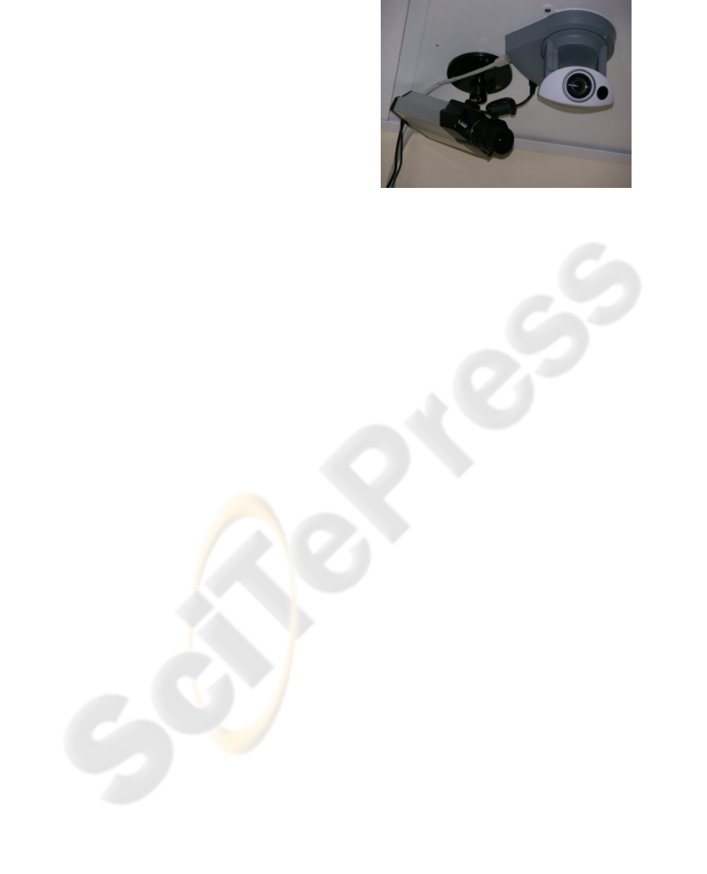
Figure 1: Our system of collocated cameras : the static cam-
era is on the left and the dynamic camera is on the right.
To steering the dynamic camera, they need to know a
sequence of transformations to allow to link a position
with the pan-tilt angles. These transformations are
adapted to pedestrian tracking. An homography links
the foot position of the pedestrian in the static cam-
era with the foot position in the dynamic camera. A
transformation links the foot position in the dynamic
camera with the head position in the dynamic camera.
Finally, another transformation, a LUT as (Zhou et al.,
2003), links the head position in the dynamic cam-
era with pan-tilt angles. These transformations are
learned automatically from unlabelled training data.
The main method default relies on the training data.
If this method is used for a turnkey solution for a no-
expert public and unfortunately the scene changes, it
is impossible that a no-expert public could constitute
a good and complete training data in order to update
the system.
A solution in the continuity of (Zhou et al., 2003)
and (Senior et al., 2005) works is proposed. Indeed,
(Jain et al., 2006) need the depth information of the
object in the scene. So they need to use stereo triangu-
lation. But, like in figure 1, this system is composed
of two almost collocated cameras.
Moreover, for an automatic and autonomous sys-
tem, solutions proposed by (Jain et al., 2006) and (Se-
nior et al., 2005) are not usable. In fact, they need
an expert knowing precisely how to use a calibration
target (Jain et al., 2006) or how to extract the good
informations to make the training data (Senior et al.,
2005).
In this paper, an automatic and autonomous solu-
tion is presented for an uncalibrated pair of cameras.
The solution adapts automatically to its environment.
In fact, if the pair of cameras are in a changing envi-
ronment, this solution can be restarted regularly.
HYBRID DYNAMIC SENSORS CALIBRATION FROM CAMERA-TO-CAMERA MAPPING: AN AUTOMATIC
APPROACH
499
2 AUTOMATIC SUPERVISED
MULTI-SENSOR
CALIBRATION METHOD
This section describes the calibration algorithm. The
method is presented in two main steps. First, the
computation of a camera-to-camera mapping (LUT)
is explained in order to link a position in the scene
with pan-tilt parameters (figure 2). Secondly, the
method to extend LUT is proposed in order to get
dense matching.
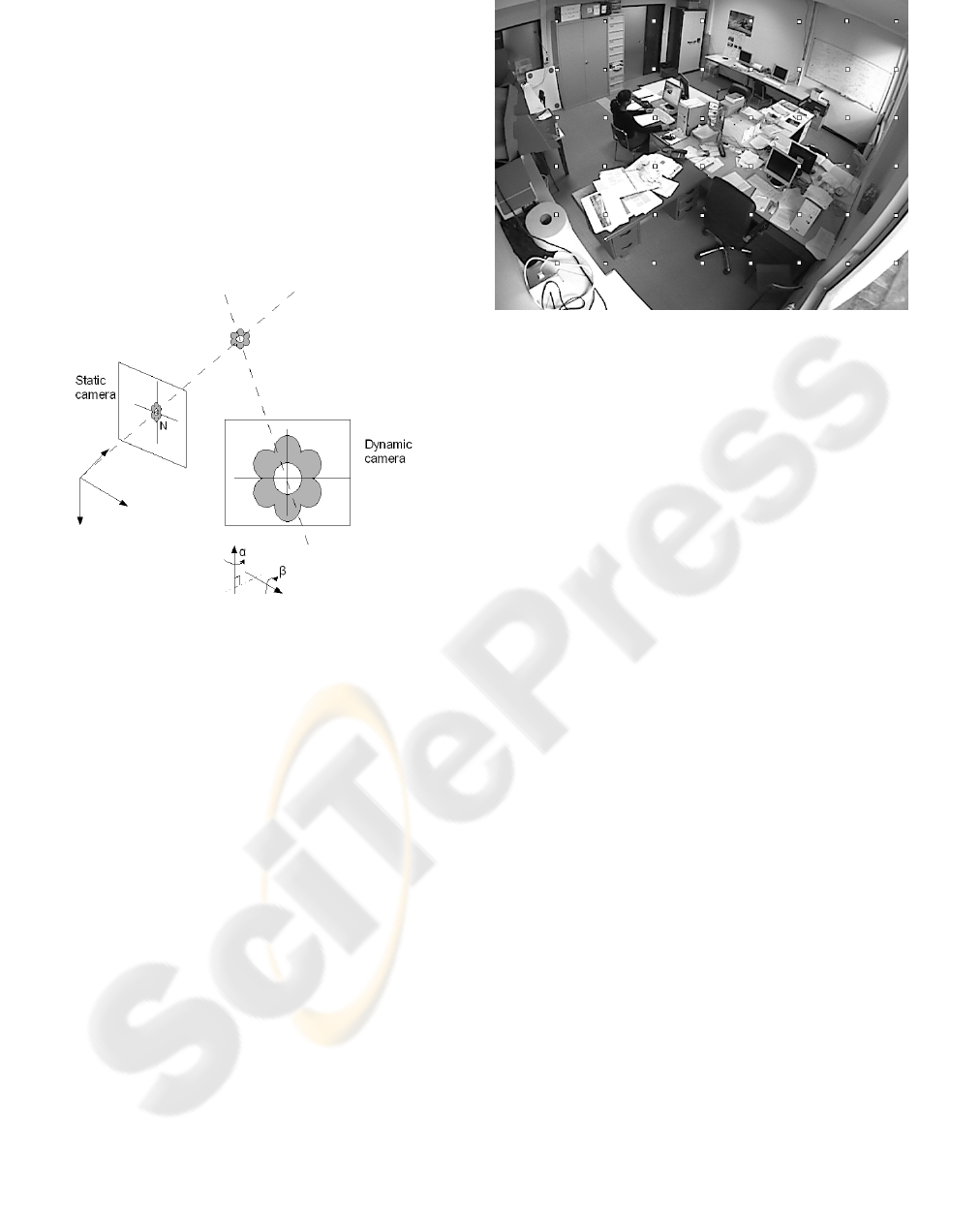
Figure 2: Scheme of the static-dynamic cameras devices.
2.1 Camera-to-Camera Calibration :
3D Scene Constraints Integration in
LUT Computation
Let us define the notations used in the following.
• I
s
: image of the static camera;
• N
i
s
: node i of the regular grid in I
s
;
• N : list of nodes N
i
s
;
• (α, β) : current pan-tilt angles of the dynamic
camera;
• I
d
(α, β) : image of the dynamic camera depending
of (α, β);
• N
i
d
: node i of the regular grid in I
d
(α, β);
• C
d
: center of I
d
;
The field-of-view of I
d
depends on the pan-tilt angles
and the zoom. In this case, the system works for a
constant zoom. The field-of-view of I
s
is 2.5 times
magnification of I
d
.
Let us denote the n
s
coordinates of N =
N
0
s
, N
1
s
, ..., N
n
s
−1
s
in I
s
. The link between the n
s
Figure 3: Grid applied to the image of the static camera.
nodes N
i
s
and the pan-tilt parameters must be known
such as N
i
s
is map to C
d
. For each node N
i
s
, a visual
servoing loop in the dynamic camera is used to learn
automatically the LUT.
Principal steps of our method :
1. Grid definition;
2. Initialisation on a node N
i
s
;
3. For each node N
i
s
in the static camera :
(a) Selection of images I
s
and I
d
(α, β) to be com-
pared
(b) Extraction and robust matching of interest
points between I
s
and I
d
(α, β)
(c) Computation of an homography H between in-
terest points of I
s
and I
d
(α, β)
(d) Computation of the N
i
s
coordinates in I
d
(α, β) :
N
i
d
= H × N
i
s
(e) Command of the dynamic camera in order to
insure that N
i
d
catch up with C
d
(f) Process N
i
s
until you reach the condition
|N
i
d
−C
d
| < ε
otherwise stop the loop after m loops
4. Go to the step (3) to process the node N
i+1
s
;
At step (1), a regular grid is applied to the image
of the static camera (figure 3). The choice of the grid
is made such as there is a common part of the field-
of-view of I
d
(α, β) between two neighbour nodes.
At the step (2), a start node N
0
s
must be selected.
To find this initial point, angles are randomly selected
to steer the dynamic camera. We stop when the field-
of-view of the dynamic camera falls in the neighbour-
hood of a node.
VISAPP 2007 - International Conference on Computer Vision Theory and Applications
500
The field-of-view of the dynamic camera is
smaller than the static one (figure 4). In order to op-
timize the matching result, a small image is extracted
at the step (3a) from the complete image I
s
around the
node N
i
s
to process.
For the step (3b), the scale-invariant feature trans-
form (SIFT) method proposed by (Lowe, 1999) for
extracting and matching distinctive features from im-
ages of static and dynamic cameras is used. The fea-
tures are invariant to image scale, rotation, and par-
tially invariant to changing viewpoints, and changing
in illumination.
At the step (3c), let us assume that locally the area
in the static and dynamic cameras can be approximate
by a plane. Locally, the distortion in I
s
can be consid-
ered insignificant. So, the homography H is searched
that best matches a set of points extracts in (3b). As
set of correspondences contains a lot of outliers, the
homography H is robustly estimated with a RANSAC
procedure. An homography is randomly computed
from only four points, and test, how many other points
satisfy it many times. The optimal solution is the
homography which has the highest number of good
points.
When the coordinates of N
i
s
in I
d
are known, the
parameters (α, β) of the dynamic camera must be es-
timated in order to insure the convergence of N
i
d
to the
center C
d
. We use a proportional controller based on
the error between the coordinates of N
i
d
and the co-
ordinates of C
d
to minimize the criterion of step (3f).
We assume that the pan-tilt axes and the coordinates
axes are collocated. So we can write the following
relation.
α
β
=
K
x→α
0
0 K
y→β
∆x
∆y
The error (∆x, ∆y) correspond to the coordinates
of N
i
d
−C
d
. As we are in a static training problem, a
proportional controller with the coefficient K
x→α
for
the horizontal direction and K
y→β
the vertical direc-
tion is sufficient.
This procedure is repeated as long as |N
i
d
−C
d
| < ε
is not achieved. If the system diverges, it stops after
m loops.
After convergence, a new node N
i+1
s
is processed.
To steer the dynamic camera in the neighbourhood
of the next point, the needed angles are estimated
with linear interpolation based on the knowledge of
the previous points. For the initial node N
0
s
, no pre-
vious nodes is known to located the next one, but
the visual servoing defines a local approximation be-
tween the variation of angles and the variation of im-
age points. The linearization is accurate enough to
estimate a rough position of the searched node.
2.2 Management of Failures :
Expansion of LUT
When the procedure seen section 2.1 is completed,
sometimes the system fails to learn the relation be-
tween some nodes N
i
s
and the pan-tilt parameters.
These failures result from the lack of interest points
around some nodes because the scene is too homo-
geneous like a part of a white wall (see top right in
figure 3). In this case, we have not enough points to
compute the homography.
In order to complete the LUT for all the pixels of
the static image, an approximation of the missing data
is searched. In such interpolating problems, Thin-
Plate-Sline (TPS) interpolation, proposed by (Book-
stein, 1989), is often preferred to polynomial inter-
polation because it obtains similar results, even when
using low degree polynomials and avoiding Runge’s
phenomenon for higher degrees (oscillation between
the interpolate points with a big variation). A TPS
is a special function defined piecewise by polynomi-
als. TPS need a training step : data which are learned
during the LUT computation. Then, for a more im-
portant grid, the corresponding pan-tilt parameters are
estimated.
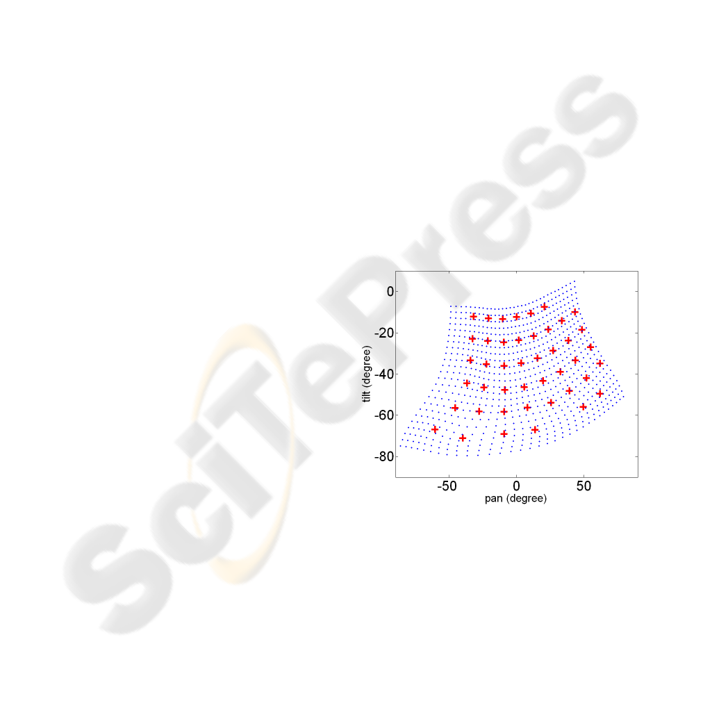
Figure 5: Result of the TPS interpolation method. Plus
correspond to the learned correspondences of the LUT and
used as training data for TPS interpolation. Points corre-
spond to the result of TPS interpolation with a more com-
plete grid than the initial grid used to learn the LUT.
3 RESULTS AND EXPERIMENTS
Cameras of the AXIS company are used. The image
resolution used is 640 × 480 pixels for I
s
and 704 ×
HYBRID DYNAMIC SENSORS CALIBRATION FROM CAMERA-TO-CAMERA MAPPING: AN AUTOMATIC
APPROACH
501


Table 1: Error in pixels committed for the horizontal (x) and
vertical (y) axes when the dynamic camera is controlled.
There are three configurations : learned scene (LS) only,
learned scene with an unknow object and learned scene with
a person. Error is estimated to four positions of subjects in
the image (case 1, ... case 4).
LS only LS + object LS + person
x y x y x y
Case 1 1.9 8.8 1.7 11.6 1.9 14.8
Case 2 2.7 2.7 5.3 4.5 5.0 10.6
Case 3 3.6 3.6 2.2 5.5 7.6 10.3
Case 4 18.9 33.4 10.6 15.2
4 CONCLUSION AND
PERSPECTIVES
In this paper, an algorithm of a camera-to-camera cal-
ibration was presented in order to steer a dynamic
camera using informations of the static camera.
Method accuracy reaches the minimal mechanical
step allowed by the dynamic camera device. More-
over, the accuracy decreases when the dynamic cam-
era is centered on an unknow subject. But it is suffi-
cient to initialize a tracking phase with the dynamic
camera.
In the future, grid definition and zoom integration
must be changed.
Actually, a regular grid without relation with the
3D content of the scene is used. A grid based on the
results of the SIFT method is more interesting. For
instance the choice of the points as a gravity center of
an area with a good density of interest points in order
to make more robust our method can be used.
Secondly, if people high resolution images are
recorded during a tracking step, it is necessary to inte-
grate the zoom to this system. So, for each zoom, the
same procedure will be used to learn the correspond-
ing LUT and then to construct a 3D LUT giving the
relation between the coordinates of point in the static
camera with the pan-tilt-zoom parameters of the dy-
namic camera.
REFERENCES
Barreto, J. P., Peixoto, P., Batista, J., and Araujo, H. (1999).
Tracking multiple objects in 3d. IEEE Intelligent
Robots and Systems.
Basu, A. and Ravi, K. (1997). Active camera calibration
using pan, tilt and roll. IEEE Transactions on Systems
Man and Cybernetics.
Bookstein, F. L. (1989). Principal warps: Thin-plate splines
and the decomposition of deformations. IEEE Trans-
actions on Pattern Analysis and Machine Intelligence.
Collins, R. T. and Tsin, Y. (1999). Calibration of an outdoor
active camera system. IEEE Computer Society.
Davis, J. and Chen, X. (2003). Calibrating pan-tilt cameras
in wide-area surveillance networks. In ICCV ’03: Pro-
ceedings of the Ninth IEEE International Conference
on Computer Vision. IEEE Computer Society.
Horaud, R., Knossow, D., and Michaelis, M. (2006). Cam-
era cooperation for achieving visual attention. Ma-
chine Vision Application.
Jain, A., Kopell, D., Kakligian, K., and Wang, Y.-F.
(2006). Using stationary-dynamic camera assemblies
for wide-area video surveillance and selective atten-
tion. In IEEE Computer Vision and Pattern Recogni-
tion. IEEE Computer Society.
Lowe, D. G. (1999). Object recognition from local scale-
invariant features. In Proc. of the International
Conference on Computer Vision ICCV, Corfu, pages
1150–1157.
Otsu, N. (1979). Aa threshold selection method from grey
scale histogram. IEEE Transactions on Systems Man
and Cybernetics.
Senior, A. W., Hampapur, A., and Lu, M. (2005). Acquiring
multi-scale images by pan-tilt-zoom control and auto-
matic multi-camera calibration. In WACV-MOTION
’05: Proceedings of the Seventh IEEE Workshops on
Application of Computer Vision (WACV/MOTION’05)
- Volume 1. IEEE Computer Society.
Shih, S., Hung, Y., and Lin, W. (1998). Calibration of an
active binocular head. IEEE Transactions on Systems
Man and Cybernetics.
Woo, D. and Capson, D. (2000). 3d visual tracking using a
network of low-cost pan/tilt cameras. IEEE Computer
Society.
Zhou, X., Collins, R., Kanade, T., and Metes, P. (2003). A
master-slave system to acquire biometric imagery of
humans at distance. In ACM International Workshop
on Video Surveillance. ACM Press.
HYBRID DYNAMIC SENSORS CALIBRATION FROM CAMERA-TO-CAMERA MAPPING: AN AUTOMATIC
APPROACH
503

