
DEMOSAICING LOW RESOLUTION QVGA BAYER PATTERN
Tommaso Guseo and Emanuele Menegatti
Intelligent Autonomous Systems Laboratory (IAS-Lab), The University of Padua
Keywords:
Robot vision, demosaicing, QVGA resolution, Bayer pattern.
Abstract:
In this paper, we present a solution for the interpolation of low resolution digital images. Many digital cameras
can function in two resolution modes: VGA (i.e., 640×480) and QVGA (i.e., 320×240). These cameras use a
single sensor covered with a Color Filter Array (CFA). The CFA allows only one color component to be mea-
sured at each pixel, the remaining color components must be interpolated, this operation is called demosaicing.
There is not a standard way to interpolate the QVGA Bayer pattern and most of the known demosaicing al-
gorithms are not suitable. In this paper, we propose a new solution for the interpolation of QVGA Bayer
pattern. Experimental results using digital images and an evaluation function confirm the effectiveness of the
interpolation method. The use of the QVGA resolution is important in low-cost and low-power embedded
hardware. As an application, we chose the RoboCup domain and in particular our Robovie-M humanoid robot
competing in the RoboCup Kid-Size Humanoids League.
1 INTRODUCTION
Color digital cameras are popular today. They can
be found also in PDA cellular phone, etc. CMOS
digital cameras are more and more often used in au-
tonomous robots to acquire images of the environ-
ment surrounding a robot. Most cameras use a single
light sensor covered with a Color Filter Array (CFA).
The CFA is a colored filter that allows only one color
component to be measured at each pixel, the remain-
ing color components must be interpolated: this op-
eration is called demosaicing. Several patterns exist
for the CFA, the most common is the Bayer pattern,
shown in Fig. 1(a). Many algorithms for demosaic-
ing the Bayer pattern exist in literature. In this pa-
per we focus on low computational cost algorithm
that are intended for embedded low power systems.
Low cost digital cameras with CFA can acquire im-
ages at different resolutions: the most important are
high resolution VGA and low resolution QVGA. In
low resolution acquisition mode, the Bayer pattern is
sampled to reduce the data rate. This reduction is ob-
tained skipping two consecutive columns every four,
as shown in Fig. 1(b), obtaining what we call QVGA
Bayer pattern. In this paper, we propose a new so-
lution for the interpolation of QVGA Bayer pattern,
obtained sampling only columns, based on periodic
reconstruction. The QVGA resolution is adopted in
many devices such as cellular phones and PDAs with
inexpensive cameras. The QVGA interpolation algo-
rithm proposed in this paper could also be used to im-
prove the color image acquisition in these handheld
devices or for image visualization in small LCDs. We
use QVGA low resolution mode in our Kid-Size Hu-
manoid to reduce the data rate and to improve image
processing speed, maintaining a large field of view
and reducing the resolution. We use QVGA resolu-
tion for full field of view and VGA for focalized view
reduced to a region of interest of the image, where an
object of interest has been detected. We also introduce
an evaluation function to compare the different inter-
polation methods for QVGA; this function shows ef-
fectiveness of improvement of quality in interpolation
results due to periodic reconstruction. The remainder
of the paper is organized as follows. In Section 2, we
summarize the most common interpolation methods
for the Bayer pattern. In Section 3, we present basic
interpolation methods for QVGA Bayer pattern and
141
Guseo T. and Menegatti E. (2007).
DEMOSAICING LOW RESOLUTION QVGA BAYER PATTERN.
In Proceedings of the Second International Conference on Computer Vision Theory and Applications - IFP/IA, pages 141-146
Copyright
c
SciTePress
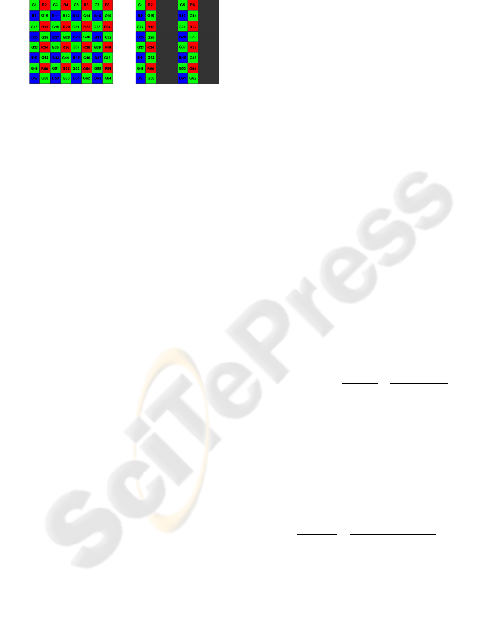
(a) VGA mode. (b) QVGA mode.
Figure 1: Bayer pattern base structure VGA and QVGA
mode.
the new one proposed by us. In Section 4 these al-
gorithm are compared using quality evaluation func-
tions.
2 DEMOSAICING BAYER
PATTERN
Consider a 2×2 base grid, the Bayer pattern measures
the G in two diagonal pixel and the R and B in the
others, as shown in Fig. 1(a). The G component is
measured twice with respect to R or B because the
peak sensitivity of the human visual system lies in the
medium wavelengths, corresponding to the G portion
of the visible spectrum. The computer vision commu-
nity has devoted many efforts to the problem of Bayer
pattern demosaicing. There are many algorithms to
interpolate the Bayer pattern. In this paper, we con-
sider only low computational algorithm. For a com-
prehensive description of the current state of the art
see the work of Gunturk et al. (Gunturk et al. (2005)).
The Nearest Neighbor Replication method is the
simplest algorithm for demosaicing CFA images. It is
analyzed in the works of (Parulski (1985)), (Adams
and Hamilton (1997)), (Zen et al. (1998)) and of
(Sakamoto et al. (1998)). The algorithm is non–
adaptive, i.e. operates in the same way for all pixel
of the same components in every images. The value
of each interpolated pixel is obtained by copying the
value of the nearest pixel in the Bayer pattern im-
age. The nearest pixel can be any one of the pixel
in the neighborhood: upper, lower, left and right pix-
els. This algorithm does not involve any arithmetic
operation and therefore this method does not impose
a heavy computational cost. However there are many
negative aspects: creation of false colors and high
chromatic gradient transitions become irregular, this
effect is called zipper effect.
The Bilinear Interpolation is the most used algo-
rithm for demosaicing CFA images. It is analyzed in
the works of (Parulski (1985)), (Wu et al. (1997)),
(Chan et al., 1996), (Tsai et al. (1997)), (Zen et al.
(1998)), (Adams et al. (1998)) and also of (Sakamoto
et al. (1998)). In other works, such as in (Lukin
(2004a)). Bilinear Interpolation method forms the
base for more sophisticated algorithm; in (Malvar
(2004)) this method is studied for non–linear interpo-
lation algorithm on rhomboidal grid. The algorithm
is non–adaptive. There are two privileged directions
(i.e., vertical and horizontal) and pixels are bilinearly
interpolated along these directions.
An interpolation algorithm that has good perfor-
mances in terms of quality of reconstruction is Linear
Interpolation with Laplacian Second–order Correc-
tion Terms that we adopted in our application. The
Linear Interpolation with Laplacian Second–order
Correction Terms is an adaptive algorithm, i.e. it
changes the interpolation equation adapting to the im-
age to be interpolated. This algorithm is analyzed in
(Hamilton and Adams (1997)) and with modifications
in (Adams and Hamilton (1997)) and (Adams et al.
(1997)). Interpolation of the green component has to
be computed before the other components. Consider
interpolation of green component in blue pixel, see
Fig. 2(a), for example G5 in B5. Calculate gradient in
horizontal (∆H), and vertical (∆V) direction
∆H = |G4− G6| + |B5− B3+ B5− B7| ; (1)
∆V = |G2− G8| + |B5− B1+ B5− B9| . (2)
Then evaluate which interpolation fuction has to
be used:
∆H < ∆V → G5 =
(G4+G6)
2
+
(2·B5−B3−B7)
4
;(3)
∆H > ∆V → G5 =
(G2+G8)
2
+
(2·B5−B1−B9)
4
;(4)
∆H = ∆V → G5 =
(G2+G4+G6+G8)
4
+ (5)
+
(4·B5−B1−B3−B7−B9)
8
. (6)
For red and blue components are possible tree
cases, consider Fig. 2(b):
1. interpolate red or blue component in green posi-
tion when nearest same color components are in
the same column. Consider R4 in G4, interpola-
tion is done with (7)
R4 =
(R1+ R7)
2
+
(G4− G1+ G4− G7)
4
; (7)
2. interpolate red or blue component in green posi-
tion when nearest same color components are in
the same row. Consider R2 in G2, interpolation is
done with (8)
R2 =
(R1+ R3)
2
+
(G2− G1+ G2− G3)
4
; (8)
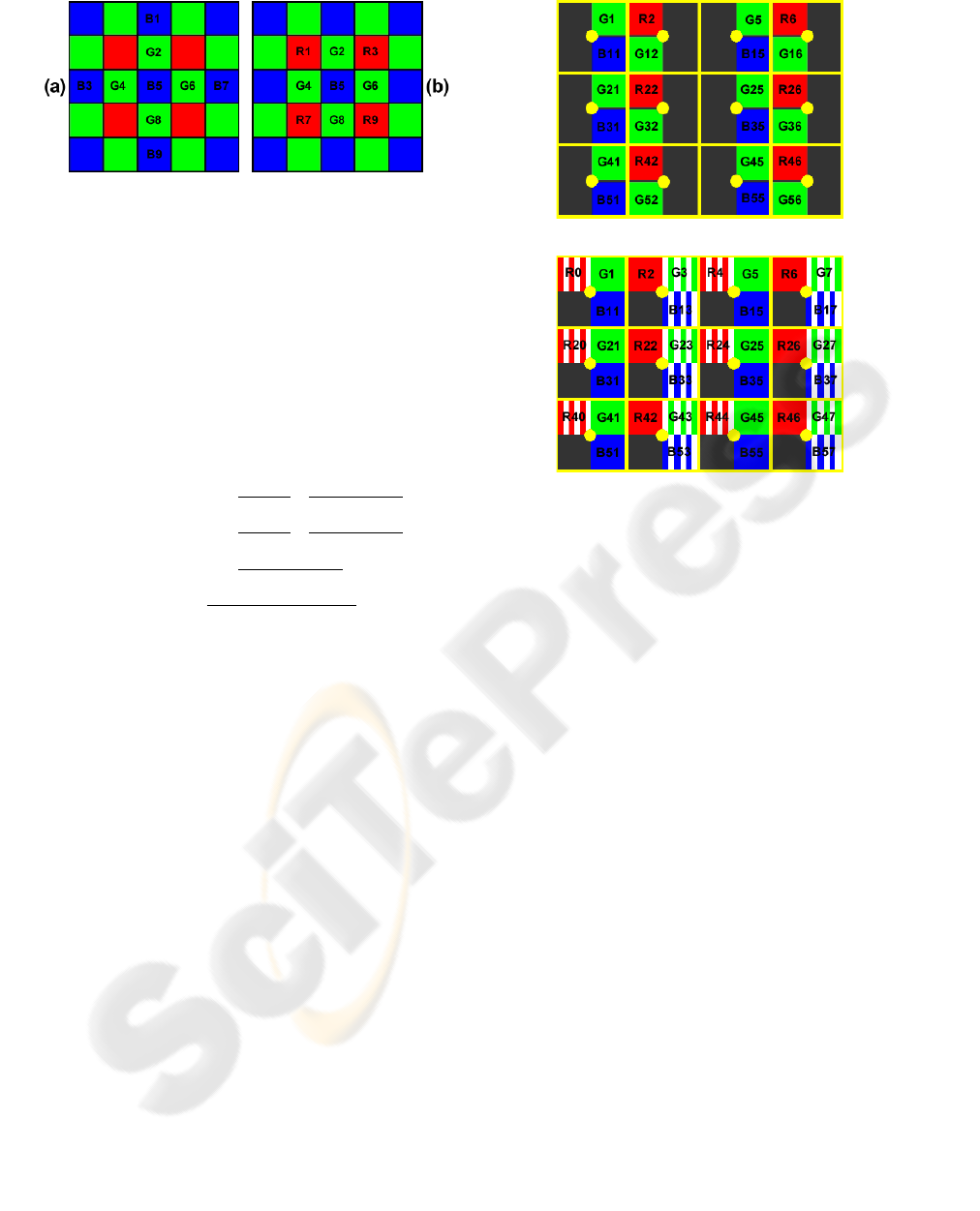
Figure 2: Linear Interpolation with Laplacian Second–order
Correction Terms in VGA Bayer pattern.
3. interpolate red or blue component in blue or red
position. Consider R5 in B5. Define diagonal gra-
dient in negative direction ∆N (9) and in positive
direction ∆P (10).
∆N = |R1− R9| + |G5− G1+ G5− G9| ;(9)
∆P = |R3− R7| + |G5− G3+ G5− G7| .(10)
Then evaluate which interpolation fuction has to
be used:
∆N < ∆P → R5 =
(R1+R9)
2
+
(2·G5−G1−G9)
4
; (11)
∆N > ∆P → R5 =
(R3+R7)
2
+
(2·G5−G3−G7)
4
; (12)
∆N = ∆P → R5 =
(R1+R3+R7+R9)
4
+ (13)
+
(4·G5−G1−G3−G7−G9)
8
. (14)
3 DEMOSAICING QVGA BAYER
PATTERN
As we already said in the introduction, the QVGA
Bayer pattern is obtained sampling the Bayer pattern
skipping two columns every four, see Fig. 1(b). To
the best of our knowledge, there is not a standard way
in literature to interpolate the QVGA Bayer pattern.
In this paper we propose a new interpolation method.
The main idea originates from an original work of
(Tang and Lee (2004)) about interpolation of classical
Bayer pattern. In that work, Tang and Lee proposed
a vertex based interpolation method instead of center
based interpolation method.
Similarly, we based our interpolation algorithm
for QVGA on vertex interpolation mode (i.e. the
interpolated pixels are centered on the vertex of the
Bayer pixels). This is sketched in Fig. 3(a). The inter-
polated pixel is the yellow square binding 2x2 Bayer
pixels. The yellow dot represents the center of the
interpolated pixel. With respect to the VGA Bayer
pattern, the QVGA Bayer pattern has the following
peculiarities:
(a) QVGA structure.
(b) QVGA periodic reconstruction.
Figure 3: Base structure of QVGA and periodic reconstruc-
tion.
1. in each yellow square one color component is
missing;
2. the vertical periodicity of the grid is of 2 pixels,
while the horizontal is of 4 pixels;
3. in the yellow squares along the same column is
missing always the same color component;
In the next paragraphs, we will show how the
Nearest Neighbor Replication algorithm and the Bi-
linear Interpolation algorithm could be applied to the
QVGA Bayer pattern. We will see that both algo-
rithms perform poorly, basically because they do not
use a periodic pattern for the color components. We
propose a new method called Periodic Reconstruc-
tion Interpolation in which some of the color compo-
nents are interpolated to obtain a periodic color pat-
tern, that is equally repeated in every yellow square
of the QVGA image, as depicted in Fig. 3(b). Interpo-
lated pixels are always painted with the corresponding
color and white bar pattern.
The Nearest Neighbor Replication algorithm is
the simplest non–adaptive algorithm for demosaic-
ing QVGA images. The green component does not
need to be interpolated; every yellow square contains
a green pixel of the QVGA Bayer pattern. The red
and the blue pixels are obtained by replicating, re-
spectively, the nearest right pixel and the left near-
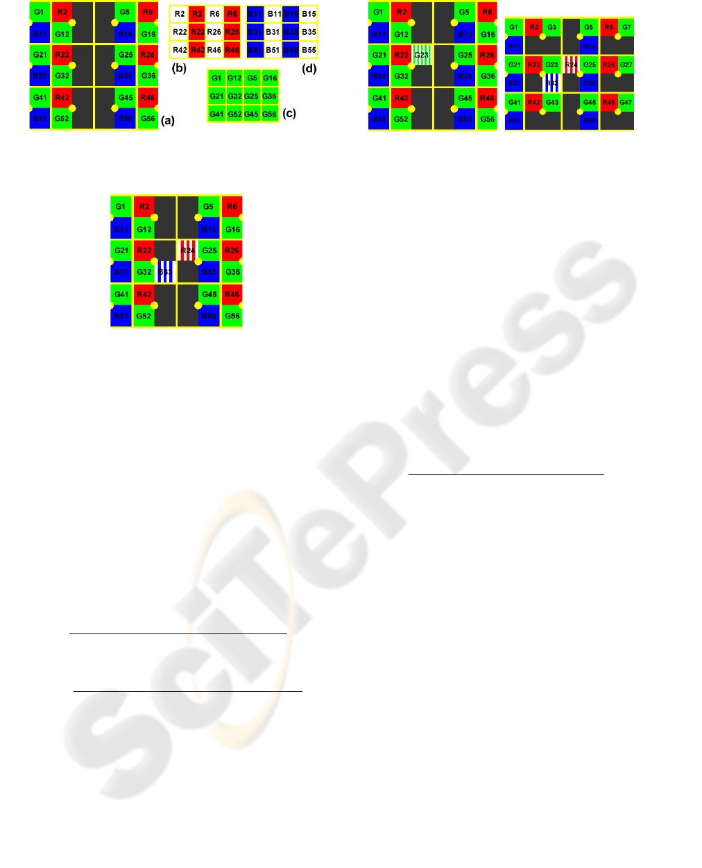
Figure 4: Nearest Neighbor Replication in QVGA Bayer
pattern.
Figure 5: Bilinear interpolation in QVGA Bayer pattern.
est pixel, as shown in Fig. 4. The pros and cons of
this method are the same as the algorithm presented
in VGA mode: low computational cost, presence of
false color and zipper effect.
The Bilinear Interpolation algorithm is a non–
adaptive algorithm for demosaicing QVGA images,
that makes an average on vertical and horizontal di-
rection. The green component, as in Nearest Neigh-
bor Replication algorithm, is not interpolated. For the
interpolation of red and blue components, see Fig. 5,
is not possible to have an exactly bilinear interpola-
tion, because the color information in vertical direc-
tion is always absent. The interpolation method uses a
weighted mean based on the distance. For a red pixel,
for example R24, the value is obtained with (15)
R24 =
(4·R22+ 4·R26+ 3·R2+ 3·R6+ 3·R42+ 3·R46)
20
, (15)
and for a blu pixel, as B33, consider Eq. (16)
B33 =
(4·B31+ 4·B35+ 3·B11+ 3·B15+ 3·B51+ 3·B55)
20
.
(16)
Unfortunately this algorithm blurs the image by
averaging over all pixels without any appropriate
weighting. Even this algorithm is affected by the zip-
per effect.
A thorough analysis of the Nearest Neighbor
Replication and Bilinear Interpolation algorithms
when used for the interpolation of QVGA Bayer pat-
tern shows that they do not correctly interpolate the
green component. This problem arises from the non–
(a) Green. (b) Red and Blue.
Figure 6: Periodic Reconstruction Intepolation in QVGA
Bayer pattern.
periodic interpolation domain (i.e., the distance be-
tween two green pixels varies along the grid). This
results in a wrong attribution to green components.
We propose first to interpolate the green components
to construct the periodic grid of Fig. 3(b), from this
the name Periodic Reconstruction Interpolation, and
then to interpolate the red and blue components.
The green component in every yellow square is
obtained as the average of the nearest green Bayer
pixels weighted by their distances. As an example
consider pixel G23, as shown in Figure 6(a). The in-
terpolation is obtained by (17)
G23 =
(3·G21+ 4·G12+ 4·G32+ 3·G25)
14
. (17)
To limit the low-pass filter effect due to the aver-
age operation, we perform it only on pixel closer than
two pixels from the interpolation center.
The next step is to create a periodic structure also
for these components. Consider Fig. 6(b) where green
pixels have been already interpolated by the Eq. (17).
We propose an adaptive algorithm for interpolation of
red and blue pixels.
Consider red pixel R24. We define diagonal gra-
dients in negative direction as ∆N (18) and in positive
direction as ∆P (19) and the horizontal gradient as ∆O
(20).
∆N = |R2−R46| + |G25−G3+G25−G47| ;(18)
∆P = |R6−R42|+ |G25−G7+G5−G43| ; (19)
∆O = |R22−R26|+ |G25−G23+G25−G27| .(20)
The value of every interpolated pixel is calculate
with Algo 3.1 depending on which of the gradient is
maximum. The interpolation of blue pixel is done in
the same way.
Algorithm 3.1 QVGA Periodic Reconstruction Inter-
polation.
1: for all i is pixel has to be interpolated do
2: A = max(∆N, ∆P, ∆O)
3: if (A == ∆N) then
4: R24 =
(R2+R46)
2
+
(2·G25−G3−G47)
4
5: else if (A == ∆P) then
6: R24 =
(R6+R42)
2
+
(2·G25−G7−G43)
4
7: else if (A == ∆O) then
8: R24 =
(R22+R26)
2
+
(2·G25−G23−G27)
4
9: else
10: R24 =
(4·R22+4·R26+3·R2+3·R6+3·R42+3·R46)
20
11: end if
12: end for
4 ALGORITHM QUALITY
EVALUATION
To compare the quality of the images reconstruction
with different algorithms, in addition to the visual
comparison of the reconstructed images, we use the
dependency index developed in (Guseo T. (2006)).
This index is based on the concept of entropy, see
(Guseo R. (2006)).
The original and reconstructed images to be com-
pared has to be considered as a linear array. In bivari-
ate case the dependency index
P|F
˜
D is defined as (21),
where P represent the pixel’s position in the linear ar-
ray and F indicates the original and reconstructed im-
age.
F
H and
P
H is denoted the marginal entropy re-
spect figure (F) and position (P), with
PF
H the joined
entropy and with
PF
I the information between origi-
nal and reconstructed figure.
P|F
˜
D =
PF
I
P
H
=
F
H +
P
H −
PF
H
P
H
. (21)
In the trivariate case, where third qualitative variable
is color (C) we consider the partial dependency index
without effect of color (22)
P|F
˜
D
C
=
P|C
H −
P|FC
H
P|C
H
=
PC
H −
C
H −
PFC
H +
FC
H
PC
H −
C
H
.
(22)
The dependency indexes are for construction nor-
malized in the range [0, 1]. If two images are very
similar the dependency index tends to 0.
We use dependency indexes
P|F
˜
D
(R)
,
P|F
˜
D
(G)
and
P|F
˜
D
(B)
for bivariate case for each single components
and
P|F
˜
D
(T)
for image in all components. We use
partial dependency index without effect of color
P|F
˜
D
C
for trivariate case.
To assess to interpolation quality of different al-
gorithm proposed, consider the Tab. 1 the which are
listed dependency indexes. Periodic Reconstruction
has
P|F
˜
D
(G)
index that is half than other methods.
This represent a good improvement in interpolation
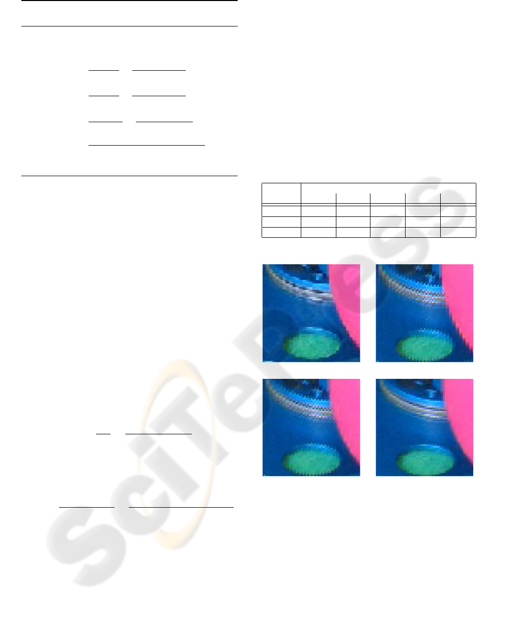
quality. In Fig. 7 interpolation algorithms have been
visually compared . It is visible the presence of zip-
per effect an false colors in Fig. 7(b) and Fig. 7(c)
corresponding to Nearest Neighbor Replication and
Bilinear Interpolation alortithm. The Fig. 7(d) ob-
tained with Periodic Reconstruction algorithm has
sharp edges and no zipper effects.
Table 1: Comparison between interpolation methods on
QVGA Bayer pattern, all values are in 10
−5
.
Dependency index
P|F
˜
D
(R)
P|F
˜
D
(G)
P|F
˜
D
(B)
P|F
˜
D
(T)
P|F
˜
D
C
Neighbor 10.4765 5.8445 23.1138 10.2245 11.0308
Bilinear 10.9063 5.8445 22.6590 10.2537 11.0618
Periodic 7.3436 2.4420 15.2124 6.8667 7.5032
(a) Original (b) Neighbor
(c) Bilinear (d) Periodic
Figure 7: Visive comparison between QVGA interpolation
methods.
5 CONCLUSION
The use of QVGA format is important in low cost and
low computational power systems as embedded PCs,
PDAs and cellular phones. In this paper we present
a new interpolation method for QVGA Bayer pattern:
Periodic Reconstruction Interpolation. The improve-

ment of quality of the images reconstructed with pro-
posed method is demonstrated using dependency in-
dexes.
The platform on which this method is imple-
mented is Robovie-M by VStone with a Renesas CPU
at 40Mhz and a RAM of 256k–Word of 16–bit. The
digital camera used is a CMOS camera (an OV3620
by Omnivision). Acquiring the 240×240 Bayer pat-
tern with a QVGA resolution and interpolating it
with the Periodic Reconstruction Interpolation, en-
ables the robot to allocate memory space for three im-
ages to be used for image processing operations that
cannot be done in place. We reached a performance
of 2 fps on the 40Mhz CPU that has also to control 22
motors during image processing time.
At the moment of writing, we are applying the
proposed method to omnidirectional images. We are
evaluating an extension of Periodic Reconstruction
Interpolation to other patterns, for example to pat-
tern implemented in STMicroelectronics cameras, ob-
tained skipping also two rows with the same ratio.
REFERENCES
Adams, J.E. and Hamilton, J.F.: Design of practical color
filter array interpolation algorithms for digital cam-
eras, Proceedings of SPIE 3028 (1997) 117–125.
Adams, J.E. et al.: Adaptive color plane interpolation in
single color electronic camera, U.S. Patent 5 506 619
(1997).
Adams, J.E., Parulski, K. and Spaulding, K.: Color Pro-
cessing in Digital Cameras, IEEE Transactions on Mi-
croeletectronic, 18 6 (1998) 20–31.
Chan, W. et al.: A Mega-Pixel resolution PC Digital Still
Camera, Proceedings of SPIE, 2654 (1996) 164–171.
Gunturk, B.K., Glotzbach, J., Altunbasak, Y., Schafer, R.W.
and Mersereau, R.M.: Demosaicking: Color Filter Ar-
ray Interpolation, exploring the imaging process and
the correlations among three color planes in single-
chip digital cameras, IEEE Signal Processing Maga-
zine, 10 53 (2005) January 44–54.
Guseo, R: Statistica, terza ediz., Cedam, Padova (2006).
Guseo, T.: Architettura Software per Robot Umanoide Au-
tonomo, Tesi di laurea, University of Padova, Padova
(2006).
Hamilton, J.F. and Adams, J.E.: Adaptive color plane inter-
polation in single sensor color electronic camera, U.S.
Patent 5 629 734, (1997).
Lukin, A. and Kubasov, D.: An Improved Demosaicing
Algorithm, Graphicon.2004 conference proceedings,
Faculty of Applied Mathematics and Computer Sci-
ence, State University of Moscow, Russia (2004).
Malvar, H.S., He, L. and Cutler, R.: High-quality linear in-
terpolation for demosaicing of Bayer-patterned color
images, Microsoft Research One Microsoft Way, Red-
mond, WA, USA, (2004).
Maris, M.: Attention-based navigation in mobile robots us-
ing a reconfigurable sensor, Robotics and Autonomous
Systems, 34 (2001) 53–63.
Okuno, H.G., Nakadai, K., Lourens, T., Kitano, H.: Sound
and Visual Tracking for Humanoid Robot, Applied In-
telligence 20 (2004) 253–266.
Parulski, K.A.: Color Filters and Processing Alternatives
for one-chip cameras, IEEE Transactions on Electron
Devices, 32 8 (1985) August.
Reece, D.A., Shafer, S.A.: Control of perceptual atten-
tion in robot driving, Artificial Intelligence 78, (1995)
397–430.
Sakamoto, Tadashi, et al.: Software pixel interpolation for
digital still cameras suitable for a 32-bit MCU, IEEE
Transactions on Consumer Electronics, 44 4 (1998)
November 1342–1352.
Tang, B. and Lee, K.F.: An efficient color image acquisition
system for wireless handheld devices, IEEE ICASSP
2004, 3 (2004) 105–108, Multimedia Architecture
Lab Motorola Labs, Schaumburg, Illinois, USA.
Tsai, Y.T. et al.: Optimized Image Processing Algorithms
for a Single Sensor Camera, IEEE Pacific Rim Confer-
ence on Communications, Computers and Signal Pro-
cessing, 2 (1997) 1010–1013.
Vijayakumar, S., Conradt J., Shibata, T. e Schaal, S.: Overt
Visual Attention for a Humanoid Robot, Proc. Inter-
national Conference on Intelligence in Robotics and
Autonomous Systems, IROS (2001).
Wu, X. et al.: Color Restoration from Digital Camera
Data by Pattern Matching, Proceedings of SPIE, 3018
(1997) April 12–17.
Zen, Hidemori, et al.: A New digital signal processor for
progressive scan CCD, IEEE Transactions on Con-
sumer Electronics, 44 2 (1998) May 289–295.
