
ONTOLOGY-DRIVEN 3D RECONSTRUCTION OF
ARCHITECTURAL OBJECTS
Christophe Cruz, Franck Marzani
Laboratoire Le2i, UFR Sciences et Techniques, Université de Bourgogne
B.P. 47870, 21078 Dijon Cedex, France
Frank Boochs
Institut i3mainz, am Fachbereich 1 - Geoinformatik und Vermessung
Fachhochschule Mainz, Holzstrasse 3655116 Mainz
Keywords: Scanning, automatic reconstruction, architectural objects, knowledge database detection, semantic,
ontology.
Abstract: This paper presents an ontology-driven 3D architectural reconstruction approach based on the survey with a
3D scanner. This solution is powerful in the field of civil engineering projects to save time during the cost
process estimation. This time is saved using efficient scanning instruments and a fast reconstruction of a
digital mock-up that can be used in specific software. The reconstruction approach considers the three
following issues. How to define an ontology to drive the reconstruction process? How to find semantic
objects in a cloud of points? How to control an algorithm in order to find all objects in the cloud of points?
This paper underlines the solutions found for these questions.
1 INTRODUCTION
In the field of civil engineering projects it is often
difficult to update a building. Most of the time,
information concerning its design has simply
disappeared. Indeed, no process was usually defined
to store digital data concerning the design of the
architectural project. Such data would be helpful to
estimate the update costs. For instance, the security
laws evolve and the buildings have to follow them.
Consequently, the buildings must be updated too.
Also, the building has to be captured “as-built” using
expensive geometrical measurements to improve the
design and to evaluate the update costs. These
measurements have to be done by engineers and
comprise several steps like the establishment of a
geometrical reference and a local data capture. This
process is time consuming, that’s why automatic
algorithms are welcome in order to reduce time and
cost. In principle, photogrammetry and laser
scanning both have the potential for improvements
and higher degrees of automatism. In this article we
focus on a method based on the laser scanning
survey. Digital building plans being defined by the
civil engineers with the help of CAD software
mostly contain simple geometries. In addition,
semantic rules are applied to achieve better design.
However, during various processing steps and their
inevitable data exchange object information is
reduced to a set of vectors using formats like DXF
or DWG. As a consequence, semantic information
and object structures are lost. Such problems might
be avoided with file formats like IFC, defined by the
International Alliance for Interoperability. This
standard associates a semantic definition to
geometrical elements in the field of building
projects. Up to now, this standard is used as an
exchange format by international leaders of CAD
software. This format is of value for "as-built"
problems, aiming at the digital reconstruction of real
buildings. Consequently, it should be helpful to use
the IFC semantic information directly during an “as-
built” reconstruction of a building for an automatic
reconstruction. In this article we focus on a method
not only based on the laser scanning survey and IFC
semantics but also introducing an ontology defining
47
Cruz C., Marzani F. and Boochs F. (2007).
ONTOLOGY-DRIVEN 3D RECONSTRUCTION OF ARCHITECTURAL OBJECTS.
In Proceedings of the Second International Conference on Computer Vision Theory and Applications, pages 47-54
DOI: 10.5220/0002047300470054
Copyright
c
SciTePress

the semantic context to simplify the automatic
reconstruction.
The following section gives background
information on projects that aim to reconstruct a 3D
model of a building from survey data. In these
projects the semantic information that describes the
context of the building takes an important place.
Section 3 describes our approach inspired from these
projects. Section 4 focuses on this method by
explaining all the important parts of the
reconstruction process.
2 BACKGROUND
Today, computer-driven evaluation of spatial data
sets is limited by the complexity of the objects to be
extracted. As a matter of fact it is complicated and
time consuming to formulate rules in order to detect
and extract objects geometrically correct. It is due to
one essential reason that the objects are broken
down into many small geometrical pieces. Even if
each piece can be treated in an isolated way, it is not
possible to treat all data at one time. Therefore, the
use of knowledge and its introduction into the
process of evaluation is promising for global
interrelations. The impact of semantic information
on the reconstruction process depends on the
structure of the raw data that has to be handled.
Therefore, it is necessary to study those structures
and reconstruction processes. A short survey is
given in the two following subsections. The first
subsection is concerned with reconstruction methods
based on photogrammetric data and the second
considers reconstruction methods based on scanning
data. Each method has its own characteristics and
advantages but the best choice depends on the
material available, the object to be captured, the
required precision, and the time available (Grün,
2002), (Bryan, 1999), (Balletti, 2004), (Boehler,
2004).
2.1 Photogrammetry
Reconstruction methods based on photogrammetric
data are of two kinds. The semi-automatic methods
consist of the interaction with the user during the
whole process. The automatic methods consist in the
initiation of the process by the user at the beginning
so that later the process runs without user
interaction. Semi-automatic reconstruction methods
can be found in the projects: Realise (Zitova, 2003),
TotalCalib (Robert, 1995), (Bougnoux, 1997),
(Faugeras, 1997), Marina (Cantzler, 2002),
(Nüchter, 2003) and Rekon (Frasson, 1999),
(Loscos, 1999), (Poulin, 1998). Automatic
reconstruction methods have been developed by
Pollefeys et al. (Pollefeys, 2000) and Zisserman et
al. (Werner, 2002). They use the projective
geometry on non-calibrated images. Pollefeys'
system combines various algorithms from computer
vision, like projective reconstruction, auto-
calibration and depth map estimation. Of special
interest for our work was the project Aida (Weik,
1996) because it uses a semantic network to guide
the reconstruction. This method opens a new way by
using semantic information. The automatic
reconstruction remains a difficult task in spite of
many years of research (Backer, 1981), (Fleet,
1991), (Grimson, 1981), (Jones, 1992), (Marr,
1979), (McMillan, 1995). The major problems are
the impact of the viewpoint onto the appearance of
the object in the image. This is due to the changes
with respect to geometry, radiometry, occlusions and
the lack of texture. Strong variations of the
viewpoint may destroy the adjacency relations of
points, especially when the object surface shows
considerable geometrical variations. This
dissimilarity causes confusion in the determination
of correspondence and it is worse when partial
occlusions result in a disappearance of object parts.
In cases of weak texture the algorithms do not have
sufficient information to solve the correspondence
problem correctly. Usually, this is the reason why
the reconstruction fails.
2.2 Scanning
Accurate reconstruction of a surface model from
unorganized points of clouds provided by scanning
systems are complex and are still not completely
solved. Problems arise from the fact that the points
are generally not organized, contain noise and do not
reflect directly the object characteristics, for
example. Computer-based processes of object
extraction are therefore limited in their efficiency. F.
Remonido gives a good overview of existing
algorithms (Remondino, 2003). Close attention is
given to the work of Cantzler et al. (Cantzler, 2002)
and to the work of Nüchter et al. (Nüchter, 2003)
because these projects use semantic information.
Planes which are being reconstructed are associated
to a semantic interpretation which has to fit to a
network model (Grau,1997). A tree of
“backtracking” allows to find the best mapping
between the scene interpretation and the semantic
network model. A coherent labelling exists if all
surfaces are labelled.
VISAPP 2007 - International Conference on Computer Vision Theory and Applications
48
Compared to photogrammetry, problems seem to
be fewer in the field of scanning but an automatic
reconstruction is just as impossible as it is within
image based techniques. One important reason for
this is the complexity of objects in combination with
redundancy, incompleteness and noise within the
clouds of points. Improvements can be expected
when knowledge about the scene is used, as is
shown in the work of Cantzler and Nüchter. This is
the reason why the nature of the geometrical objects
and the existing constraints between them make it
possible to support computer based detection.
3 ONTOLOGY-DRIVEN
RECONSTRUCTION
As the work presented in the previous section shows,
a semantic context may support considerably a 3D
reconstruction. This might be helpful for the
reconstruction within clouds of points where some
elements of the object have already been detected
and need to be combined to a final structure.
Semantic knowledge is also useful for
photogrammetric tasks. This might either help to
group 2D points in the images or to form the spatial
structure when several images are available. The
semantic structure of the spatial object model is the
same, only the use and the interaction with the data
are different. In the following section our vision of
the use of semantic definition for 3D reconstruction
will be sketched. Our main idea is founded on the
duality between context and constraints. It starts
from the idea that it is easier to rebuild a scene using
available knowledge about the scene’s elements.
Therefore, in order to define the knowledge about
the context, a coarse geometrical and semantic
model has to be established. We call this c
oarse
m
odel “CM” and it is a spatial structure that defines
a building and the semantics about the elements that
compose the building.
Figure 1: Example of an architectural CM.
The “CM” (e.g. fig. 1) defines the rough
geometry and the semantics of the building without
any real measurement. Such a "CM" will then be
updated by means of real measurements representing
the building. In order to achieve this, knowledge has
to represent the real world by reflecting entities and
relations between them. Therefore, knowledge
constitutes a model of the world and agents use their
knowledge as a model of the world. In addition, to
model the semantics of knowledge as well as the
structure where this knowledge is stored, it is
necessary to reach a higher conceptual level. For
that, knowledge representation is independent of
knowledge use. Thus, knowledge representation and
inferential mechanisms are dissociated (Guarino &
al., 1994). On the other hand, domain
conceptualization can be performed without
ambiguity only if a context of use can be given. In
fact, a word or a term can designate two different
concepts depending on the particular context of use
(Bachimont, 2000). The semantic of knowledge is
strongly constrained by the symbolic representation
of computers. Therefore N. Guarino (Guarino, 1994)
introduced an ontological level between the
conceptual level and the epistemological level. The
ontological level forms a bridge between
interpretative semantics in which users interpret
terms and operational semantics in which computers
handle symbols (Dechilly, 2000). Some projects
presented previously have used a semantic network
to model the semantics of a scene. We will use an
ontology language for several reasons.
• First, the implementation of an ontology is a
mapping stage between the system elements and
their ontological “counterparts”. Once this
mapping has been carried out, the representation
of elements in the ontology is regarded as a
meta-data diagram. The role of a meta-data
diagram is double (Amann, 2003). On the one
hand, it represents the knowledge shared on a
domain. On the other hand, it plays the role of a
database schema which is used for the
formulation of requests structured on meta-data
or to constitute views.
• Secondly, the ontologies allow to dissociate
knowledge representation and inferential
mechanisms. We have sketched a generic
definition of semantic elements that permit to
dynamically add new elements in the ontology
without changing the code. Those new elements
are also taken automatically into account in the
storing process and the inferential mechanisms.
• Thirdly, once the “CM” has been corrected,
geometric and semantic information in the
ontology can be exported into an IFC file
format. So, the 3D model can be used directly in
civil engineering processes and CAD software.
ONTOLOGY-DRIVEN 3D RECONSTRUCTION OF ARCHITECTURAL OBJECTS
49
4 METHOD DEFINITION
Our method aims at developing a solution to
reconstruct automatically a 3D building from a point
cloud measured by a 3D scanner. This solution has
to consider the three following aspects. How to
define a geometric and semantic coarse model? How
to find objects in a cloud of points? Which
algorithms to use as a propagation method to find all
objects in the cloud of points? In our solution the
user has to assign the context by defining a coarse
model of the building to be reconstructed. Then the
user interactively selects a set of points in the cloud
that represents a wall. The selection is also mapped
to the coarse model by assigning the corresponding
wall in the “CM” (e.g. figure 3). Then the user starts
the reconstruction algorithm. Within an iterative
process the plane representing the wall is found and
will be used to correct the model. The process starts
with the mapped plane, corrects it, and continues
with information in “CM” to detect an adjacent
plane by propagation. A final stage should aim at the
detection of smaller parts like doors, windows, etc.
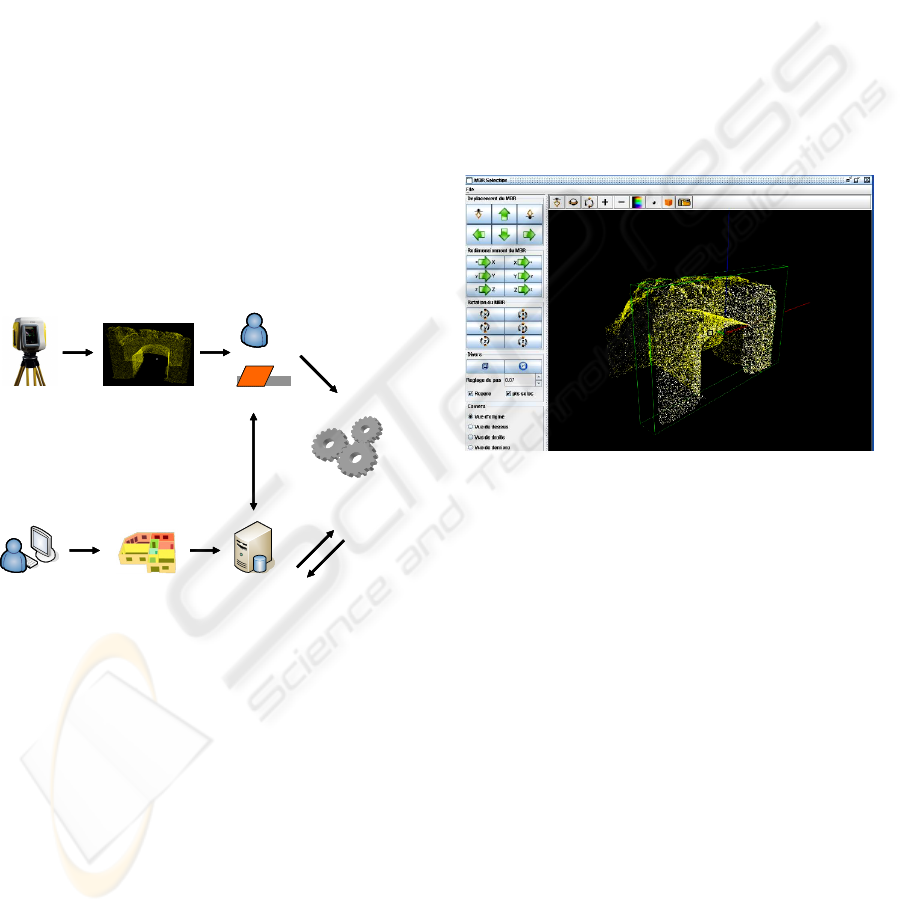
3D Scanner
User DatabaseCoarse Model
File of points
User
First plane
3D reconstruction
algorithm
Mapping
C
o
r
r
e
c
t
i
o
n
D
a
t
a
3D Scanner3D Scanner
UserUser DatabaseDatabaseCoarse ModelCoarse Model
File of pointsFile of points
User
First plane
UserUser
First plane
3D reconstruction
algorithm
Mapping
C
o
r
r
e
c
t
i
o
n
D
a
t
a
Figure 2: Global view of our method.
The three following subsections give an
overview of our solution to achieve the final goal
consisting of the definition of a “CM”, the plane
detection that allows to find objects in the cloud of
point, the search of objects by propagation
permitting the correction of the “CM”.
4.1 Definition of the “CM”
This section describes our method used to define a
“CM”. With the application that has been developed
(e.g. figure 4) the user can indicate the general
geometrical structure of a building like the position
and the size. Moreover, the interaction with our
application allows to define automatically
constraints between elements of the “CM” which are
described by the architectural ontology. For
instance, a window is a concept that composes the
architectural ontology. This window has a constraint
which is “the window must be in a wall with a
bigger size”. To implement this part we resolved
three main issues. First, it was necessary to define
the structure of the architectural ontology. Secondly,
it was necessary to manage the persistence of data as
well. Thirdly, data should be exported into an IFC
file format. To resolve the first issue, two ways were
available which are the static way and the dynamic
way. The static way consists in implementing
directly the class necessary to describe the elements
that compose a building as well as the relations.
Once the necessary elements are defined, the
conception of the databases and graphical interfaces
can be overtaken.
Figure 3: Selection of a subcloud of points.
The problem linked to the static way arises when
new kinds of objects have to be added to the
ontology. As a result, the database and the graphical
interface must be adapted. The dynamic way
consists in taking into account this issue and in
developing a structure that allows to add a new kind
of object without changing the structure of the
database and the graphical interface. The model
defined in this application takes into account this
issue and manages the description of the classes and
instances from the start.
Our model is divided into two levels which are
the semantic level and the instance level. The
semantic level allows to store the description of the
ontology classes from a OWL (Web Ontology
Language) file. The OWL file is defined with the
help of the software Protégé OWL plugin. The
instance level allows to store the description of the
instances from the classes of the ontology. The
storing process and the graphical interface are then
not modified when a new class has to be added.
Nevertheless, there is still a problem in the
VISAPP 2007 - International Conference on Computer Vision Theory and Applications
50
management of a dynamic ontology. It is necessary
to manage the positioning interactions between
elements.
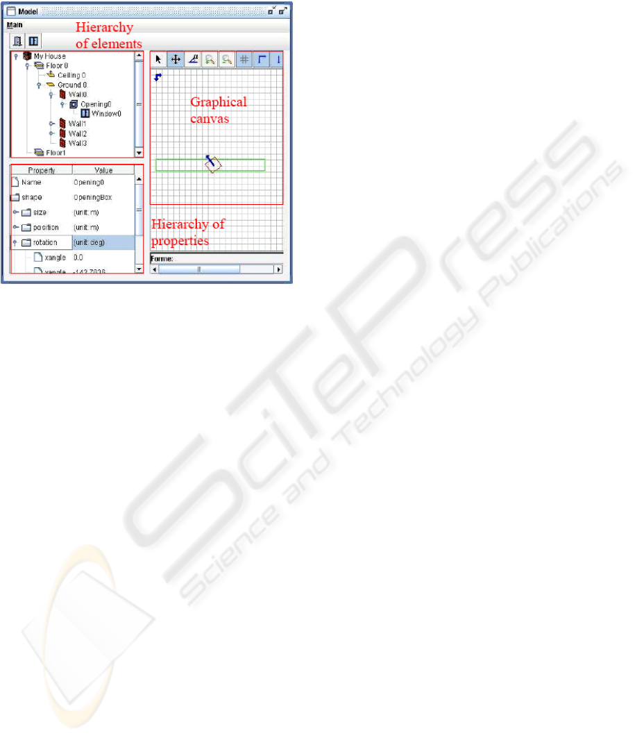
Figure 4: Definition of the “CM”.
For instance, if a ground is moved then the
elements carried by this ground, like the walls, must
undergo a displacement. The solution is to define
predefined behaviors and then associate those
behaviors of the future elements to the existing
behaviors. For example, a new class column has the
same behavior as a wall. It is indeed located on the
ground and touches the ceiling. Thus, it was
necessary to locate the types of behavior according
to the possible interactions. A set of behavior was
found but only three of them are described here. The
ground is rather a horizontally flat element and on
this one walls can be deposited. The walls are rather
vertical elements. A window is an element in a wall.
From those facts the types of elements are the
“horizontal elements”, the “vertical elements” and
the “vertical subelements”. Concerning the basic
constraints, the “horizontal elements” are used as
support for the “vertical elements”. So the ”vertical
elements” are positioned on the “horizontal
elements” and contain the “vertical subelements”.
The “vertical subelements” are contained in “vertical
elements”. With the help of those predefined
behaviors and constraints, it is easy to add a new
complex class in the architectural ontology.
Concerning the IFC export, the ontology
contains all information about the object that
composes the building. The architectural concepts
and relations are fully inspired by the IFC standard.
So, the objects are exported by our export module
with geometrical definition and the relations
between them but the constraints are only used for
the validation of the “CM”.
4.2 Plan Detection and Research by
Propagation
The objects which have to be found in the point
cloud are planes. This geometric primitive is the
easiest one to search and also the fastest one
(Remondino, 2003). During the plane search
process, there are several stages that have to be
carried out. The first stage is the partitioning of the
point cloud. When it is known that a set of points
defines only one plane, it is easier to find an
equation of the plane that represents this subset. In
most cases the point clouds do not model only one
plane. To simplify the search of planes in such a
cloud it is helpful to initially cut out such a subset of
points. After a first segmentation is achieved, one
can calculate the plane equation of each subset. But,
the equation of a plane is not sufficient for a wall
because the extensions are not contained. It is thus
necessary to limit the equation of a plane, in order to
represent the edges of the wall. The equation of a
plane provides the orientation of the wall and the
outlines are found in the point cloud.
However, this ideal situation is affected by
several real world factors. Like in all physical
measurements there will always be noise in such
measurements. In addition, the point cloud may
contain environmental objects like trees or traffic
signs partly hiding the real object. Those objects will
add more or less erroneous points that will not
represent the building. Moreover, the wall is not an
ideal mathematical planar object, leading to a
roughness of several millimetres on the surface.
Finally, not all the 3d points will be coplanar
because only in an ideal model the points can be
aligned perfectly.
All these problems must be taken into account in
the detection of planes. The noise, the erroneous
points and irregularities in the wall are parameters
which cannot be modified, and thus it is necessary to
manage them in the program. Another important
point is that the plane detection algorithm must be
automated. The user should not have to interact with
the algorithm and only has to judge that the results
are correct or not.
The degree of complexity increases enormously,
when a simple plane should be detected in a point
cloud representing a complex object. This is why the
algorithm starts with an adjacency search allowing
to group the object into small spatial elements
ONTOLOGY-DRIVEN 3D RECONSTRUCTION OF ARCHITECTURAL OBJECTS
51
(voxel). All points which are contained in a voxel
are considered as a subgroup and a plane is found
out in each voxel (e.g. figure 5). Subsequently, the
neighbourhood is used to extend the voxel planes.
The size of the voxels is an important parameter. If
the voxel size is too large then multiple planes can
be found in one voxel. Thus, it does not resolve the
problem. If the voxel size is too small then it is hard
to find a correct plane equation.
After initial planes are found, they have to be
extended within the point cloud. This is achieved by
starting from the plane equation for one voxel and
looking at the adjacent voxels if there are points
possibly belonging to the same planar surface part.
There are several methods to support such a
decision. One solution is to calculate a plane for
each voxel by means of “least square adjustement”.
This is relatively simple to set up, but needs to
define a threshold for the different angle of
orientation to define the similarity. A better solution
starts with the voxel having the best residual error
and then it consists in checking the distance to this
plane, beginning with the direct neighbours. If the
sum of the distance is lower than a certain threshold
then the voxels are fused. For the fused group a new
equation has to be calculated in order to refine the
result.
The plane search by propagation is done in an
iterative way. The process starts from a voxel and
looks at the neighbours. When the neighbours check
the same criteria then the process continues with the
"neighbours of the neighbour". Then, all planes that
have been found are checked to determine if there
are similarities between them. The method based on
the angles is also used to avoid useless calculations.
If the angle between two planes is higher than 60°,
then it is not necessary to try to see whether they can
be fused.
The plane detection in a point cloud is the most
delicate part of the process but needs, in addition, to
find the real dimensions of the various elements.
One way to achieve this might calculate a
bounding box by taking the extreme values of the
points. Some turns of this bounding box with a
predefined angle produce acceptable results. In order
to find the correct bounding box the characteristics
of the delimiting points have to be checked, because
single points cannot be regarded as reliable (e.g.
figure 7). Only a set of points allows to minimize the
errors. The most precise results will be generated by
use of the final planes constituting the walls.
Assuming the calculations of the equations were
done with large sets of points and thus of sufficient
accuracy, the edges of the walls can be calculated by
intersecting adjacent planes. The result is much
more precise and avoids the problem of the parasitic
points (e.g. figure 8).
4.3 Correction of the “CM”
The principle of the project is to use a point cloud
coming from a building survey to correct a coarse
model that defines the context. Although the
improvement of the coarse model is the most
interesting result, the initial model - and the
knowledge contained therein - is of basic importance
for the update process. Therefore, two aspects are of
interest in the context of model improvement: first,
readjusting the initial wall definition compared to
the “CM”, and, secondly, the support for the
Found rectangle
Wished
point
Parasitic
poi
nt
Similar
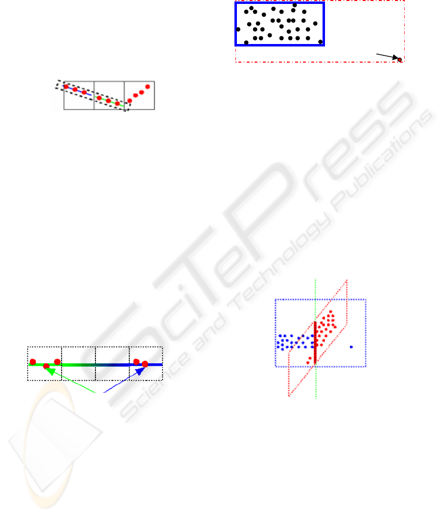
Figure 5: Plane research in voxel space.
Figure 6: Plane similarity between distant voxels.
Figure 7: Bounding box and parasitic point.
Figure 8: Plane intersection.
VISAPP 2007 - International Conference on Computer Vision Theory and Applications
52

propagation of the plane detection in the whole point
cloud.
Repositioning of the initial plane compared to the
coarse model
At the beginning, the cloud of points can be
positioned in a way completely different compared
to the “CM” coordinate system. For the search of the
other planes, it is fundamental "to readjust the cloud
of points". That readjustment defines an identical
framework that accelerates the process. This
repositioning takes place during the research of the
first plane. Once the readjusted plane has been
accomplished, the wall of the “CM” is corrected.
The correction of this wall is propagated to the
adjacent elements thanks to the constraints defined
in “CM”.
Research of nearby elements and correction
To propagate the “CM” modification a direction was
defined. The propagation is made left towards right
then bottom towards top. The “CM” contains
information of the neighbourhood. Indeed, the
neighbourhood relations are automatically defined
during the “CM” definition. To find the bounding
box of the second element, the equation of the initial
element is used to deduce from “CM” which rotation
is defined between the initial element and the second
element to be treated. The theoretical equation of the
second wall makes it possible to calculate the
distance between the second element and each point
of the cloud. Thus, by leaving an error margin, we
can detect by reading the entire file that contains the
points, all the points which are close to this plane.
Then, the sub cloud of points undergoes a detection
of plane and edges described in the preceding
section. Thanks to this information the second
element is corrected. Once all the elements from the
“CM” are corrected, the sub elements contained in
elements of the building must be corrected with the
same methods of search of plane and correction.
5 CONCLUSION
This paper presented a solution for the 3D
reconstruction driven by an architectural ontology.
At this time, most of the huge issues were resolved
and the complete process was prototyped. The
following issue to be resolved is the use of the other
primitives like the cylinder to reconstruct
automatically more complex scenes. Furthermore,
we are also working on a solution to reuse a partial
“CM” that allows to define more easily a complex
“CM”.
ACKNOWLEDGEMENTS
Authors would like to thank Jeremy Contant,
Laurent Huot and Nicolas Montelle for their
important contribution on the application
instanciation.
REFERENCES
Amann B., 2003. Du Partage centralisé de ressources Web
centralisées à l’échange de documents intensionnels,
Documents de Synthèse, 2003.
Bachimont B., 2000. Engagement sémantique et
engagement ontologique : conception et réalisation
d'ontologie en ingénierie des connaissances, In Charlet
J., Zackland M., Kessel G. & Bourigault D., eds.,
Ingénierie des connaissances : évolution récentes et
nouveaux défis, Eyrolles, pages 305-323.
Backer H. H. & Binford T. O., 1981. Depth from edge and
intensity based stereo. In Proceedinds of the seventh
IJCAI, Vancouver, BC, pages 631-636.
Balletti C. & Mander S., 2004. Contemporary Master’s
Architecture: New Architectural Heritage, Approaches
For Surveying and Representation, Geo-Imagery
Bridging Continents, XXth ISPRS Congress, 12-23
July, Istanbul, Turkey.
Boehler W. & al., 2004. The potential of non-contact close
range laser scanners for cultural heritage recording,
Actes du XVIII Symposium International CIPA,
Postdam, Allemagne.
Bougnoux S. & Robert L, 1997, TotalCalib: a fast and
reliable system for off-line calibration of images
sequences., In Proceedings of International
Conference on Computer Vision and Pattern
Recognition, The Demo Session.
Bryan P.G., Corner I. & Stevens D., 1999. Digital
Rectification Techniques for Architectural and
Archaeological, Photogrammetric Record, 16(93):
399-415, April.
Cantzler H., Fisher R. B. & Devy M., 2002. Quality
enhancement of reconstructed 3D models using
coplanarity and constraints, Proc. Annual German
Symposium for Pattern Recognition (DAGM02,
Zurich), pp 34-41.
Dechilly T. & Bachimont B., 2000. Une ontologie pour
éditer des schémas de description audiovisuels,
extension pour l'inférence sur les descriptions, In
Actes des journées francophones d'Ingénierie des
Connaissances (IC'2000).
Faugeras O., Laveau S., Robert L., Csurka G., Zeller C.,
Gauclin C. & Zoghlami I., 1997. 3-d reconstruction of
ONTOLOGY-DRIVEN 3D RECONSTRUCTION OF ARCHITECTURAL OBJECTS
53

urban scenes from image sequences., CVGIP : Image
Understanding.
Fleet D. J., Jepson A. D. & Jenkin M. R. M., 1991. Phase-
Based Disparity measurement., CVGIP : Image
Understanding, 53(2):198-210.
Frasson M., 1999. Reconstruction interactive de scènes
tridimensionnelles à partir d'images, M.Sc. Thesis,
March.
Grau O., 1997. A Scene Analysis System for the
Generation of 3-D Models, 3dim, p. 221, First.
Grimson W. E. L., 1981. From Images to Surfaces., MIT
Press.
Grün A., Bär S. & Beutner S., 2002. Signals in the Sand -
3D Recording and Visualization of the Nasca
Geoglyphs, PFG (Photogrammetrie, Fernerkundung,
Geoinformation), No. 6/2000. pp. 385-398.
Guarino N., 1994, The ontological level, in R. Casati B. S.
& White G., eds, Philosophy and the cognitive
sciences, Hölder-Pichler-Tempsky.
Guarino N., Carrara C., Giaretta P., 1994. An ontologie of
meta-level categories, in J. Doyle F. S & Torano P.,
eds., Principles of Knowledge representation and
Reasonning, Morgan-Kauffman, pages 270-280.
Huot S. & Colin C., 2002. MArINa : reconstruction de
bâtiments 3D à partir d'images., Colloque
Modélisation Multimodale appliquée à la
reconstruction d'environnements architecturaux et
urbains, Bordeaux, France.
Jones D. & Malik J., 1992. Computational Framework for
determining stereo correspondence from a set of linear
spatial filters., Image and Vision Computing,
10(10):699-708, December.
Kuzo P. M., 1999. Des contraintes projectives en
modélisation tridimensionnelle interactive, Thèse de
doctorat, Ecole des Mines de Nantes – Université de
Nantes, novembre.
Loscos C., Frasson M., Drettakis G., Walter B., Granier X.
& Poulin P., 1999. Interactive Virtual Relighting and
Remodeling of Real Scenes, Proc. Eurographics
Workshop on Rendering 99, June.
Marr D. & Poggio T., 1979. A computational theory of
human stereo vision. Proceedings of the Royal Society
of London, 204:301-328.
McMillan L. & Bishop G., 1995. Plenoptic modeling : An
image-based rendering system., In SIGGRAPH '95.
Nüchter A., Surmann H. & Hertzberg J., 2003. Automatic
Model Refinement for 3D Reconstruction with Mobile
Robots, Fraunhofer Institute for Autonomous
Intelligent Systems (AIS) Schloss Birlinghoven, D-
53754 Sankt Augustin, Germany.
Pollefeys M., Koch R., Vergauwen M. & Van Gool L.
2000. Automated reconstruction of 3D scenes from
sequences of images, ISPRS Journal Of
Photogrammetry And Remote Sensing (55)4, pp. 251-
267.
Poulin P., Ouimet M. & M. Frasson, 1998. Interactively
Modeling with Photogrammetry, Proc. Eurographics
Workshop on Rendering 98, June.
Remondino F., 2003. From point cloud to surface: the
modeling and visualization problem, Proc. Int.
Worksh. Visualization and Animation of Reality-
Based 3D Models, Int. Archives of Photogrammetry,
Remote Sensing and Spatial Information Sciences
XXXIV-5/W10, Feb.
Robert L., 1995. Camera calibration without feature
extraction, Computer Vision, Graphics, and Image
Processing, 63(2) :314–325, March also INRIA
Technical Report 2204.
Weik S. & Grau O., 1996. Recovering 3-D Object
Geometry using a Generic Constraint Description. In
ISPRS96 - 18th Congress of the International Society
for Photogrammetry and Remote Sensing, July,
Vienne.
Werner T. & Zisserman A., 2002. New Techniques for
Automated Architecture Reconstruction from
Photographs, Proc. 7th European Conference on
Computer Vision, Copenhagen, Denmark.
Zitova B. & Flusser J., 2003. Image registration methods:
A survey, Image and Vision, Computing 21, 977–
1000.
VISAPP 2007 - International Conference on Computer Vision Theory and Applications
54
