
OBSERVER BASED OPTIMAL CONTROL OF SHIP ELECTRIC
PROPULSION SYSTEM
Habib Dallagi
1
, Ali Sghaïer Tlili
2
1
Académie Navale Menzel Bourguiba, BP 7050 ,
1, 2
Ecole Polytechnique de Tunisie
BP. 743 2078 La Marsa, Tunisie
Samir Nejim
1
1
Académie Navale Menzel Bourguiba, BP 7050 ,
1, 2
Ecole Polytechnique de Tunisie
BP. 743 2078 La Marsa, Tunisie
Keywords: Electric Propulsion Ship, Optimal Control, State Observer.
Abstract: This paper describes the synthesis of a linear state observer based optimal control of ship electric propulsion
using permanent magnet synchronous motor. The proposed approach is used for the ship speed control by
measuring the stator current and the motor speed. This strategy of control is made possible by using a ship
speed state observer. A numerical simulation study, applied to the global system, has confirmed the
efficiency and the good performances of the proposed control law.
1 INTRODUCTION
The characterization of industrial processes leads, in
most cases, to nonlinear models which are generally
difficult to control. The study of such processes was
generally used by a linearization leading to a linear
model on which the linear arsenal of controls can be
applied. These different control laws use often a
state feedback. However the state vector is not
always measurable, so it is necessary to use state
observers.
The work presented in this paper concerns the
modelisation of a ship electric propulsion system.
The obtained global model is strongly nonlinear,
coupled and presenting non measurable variables.
Indeed, a linearization was firstly elaborated and the
synthesis of a control law with state feedback, for
the regulation of the stator current and the ship speed
of the synchronous motor, was secondly designed.
This control strategy is carried out using a linear
state observer allowing the ship speed
reconstruction.
This paper is organized as follows: the modeling of
the different subsystems of the ship is developed in
the section 2. The linearization model of the global
system is elaborated in section 3. Section 4 is
devoted to the optimal control development based on
state observer and in section 5 simulation resultats
are reported and discussed. Finally some conclusions
ended this work.
2 MODELISATION OF THE
ELECTRIC PROPULSION
SYSTEM
2.1 Different Parts of the Ship Electric
Propulsion System
An electric ship is generally composed by two
principal parts ( Dallagi and Nejim, 2004 ).
- a first part ensuring the energy production using
several alternators drived either by diesel motors, or
by gas turbines. It feeds the board network and the
propulsion equipment.
- a second part of electric propulsion composed by
one or two electric motors, each one of them driving
a fixed blade propeller.
2.2 Modelling of the Permanent
Magnet Synchronous Motor
By the Park transformation, the voltage equations of
the permanent magnet synchronous motor are
written as follows (Grellet and Clerc, 2000):
296
Dallagi H., Sghaïer Tlili A. and Nejim S. (2007).
OBSERVER BASED OPTIMAL CONTROL OF SHIP ELECTRIC PROPULSION SYSTEM.
In Proceedings of the Fourth International Conference on Informatics in Control, Automation and Robotics, pages 296-302
DOI: 10.5220/0001650702960302
Copyright
c
SciTePress
⎪
⎪
⎩
⎪
⎪
⎨
⎧
++=
−+=
dd
q
qqsq
qq
d
ddsd
iLp
dt
di
LiRv
iLp
dt
di
LiRv
Ω
Ω
(1)
The motor torque is given by:
(
)
qdqdqfe
ii LLpipC −+=
Φ
(2)
The mechanical equation can be written as
following:
propem
QCI −=
Ω
(3)
with:
Φ
f
: inductor flux,
R
S
: stator phase resistance,
v
d
: stator voltage longitudinal component,
v
q
: stator voltage transverse component,
i
d
: stator current longitudinal component,
i
q
: stator current transverse component,
L
d
: longitudinal inductance,
L
q
: transverse inductance,
I
m
: shaft inertia,
P : pole pairs numbers,
Ce : electromagnetic torque,
Q
prop
: propeller torque,
Ω: shaft speed.
2.3 Hull Resistance
During displacement, the ship is confronted to
several constraints among them, the sea state,
conditioned by the climatic data which is a
significant factor influencing the ship behaviour.
The sea applies a resistance which is opposed to the
ship moving forward. Thus, to study the ship
movement, it is necessary, on the one hand, to model
its displacement and, on the other hand, to know the
constraints which are opposed to its movement as
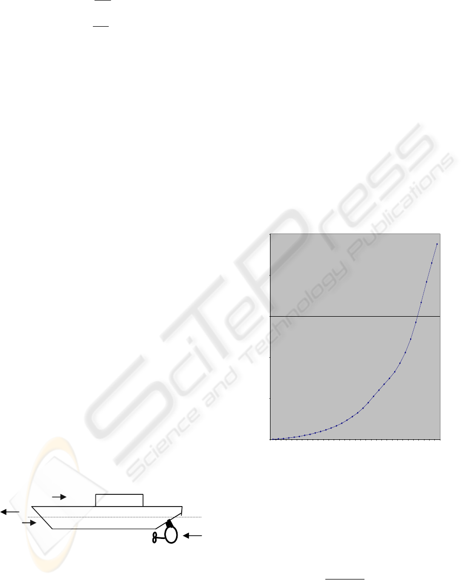
presented in the figure 1 ( Dallagi and Nejim, 2006).
Figure 1: Ship movement.
The advance total resistance to is given by:
airappwft
RRRRR +++=
(4)
with:
R
t
: advance total resistance,
R
f
: friction resistance,
R
W
: waves resistance,
R
app
: appendices resistance,
R
air
: air resistance.
This modeling is based on the resistance tests of the
ship. Thus, total resistance to advance can be
represented by the sum of four resistances (4). It is
obtained by applying different practical pulling tests
on the similarity model (Izadi-Zamanabadi and
Blank, 2001. Doutreleau and Codier, 2001).
Resistance to advance can be modeled by a function
of the following form ( Dallagi and Nejim, 2006 ):
2
t
avR =
(5)
with:
v: ship speed,
a: constant coefficient of the following curve.
Figure 2: Advance total resistance.
2.4 Equations of the Propeller
The model of propeller thrust can be written as
follows (Fosen and Blanke, 2000 ).( Guo, Zheng,
Wang and Shen, 2005):
42
T
DN
T
K
ρ
=
(6)
with T the propeller thrust given by:
T
42
KDn T
ρ
=
(7)
0
500000
1000000
1500000
2000000
2500000
1 2 3 4 5 6 7 8 9 1011121314151617181920212223242526272829303132
Speed (Nœuds)
Total resistance
T
Hull
Text
R
t
Propeller
Moto
r
v
OBSERVER BASED OPTIMAL CONTROL OF SHIP ELECTRIC PROPULSION SYSTEM
297

The model propeller torque can be written as
follows:
52
prop
Q
Dn
Q
K
ρ
=
(8)
with Q
prop
the propeller torque given by:
Q
52
prop
KDn Q
ρ
=
(9)
The coefficients K
T
and K
Q
given respectively by (6)
and (8) depend on the following parameters (Izadi-
Zamanabadi and Blank):
v
a
: advance speed (m/s), p
a
: propeller pitch,
v : ship speed (m/s), J : advance coefficient,
w : wake coefficient , n : propeller speed ( tr/s).
Coefficients K
T
and K
Q
are given from ship practical
tests. The advance coefficient is given by
(Devauchell, 1986). (Lootsma, Izadi-Zamanabadi
and Nijmeijer, 2002):
nD
v2
J
a
Π
=
(10)
and the advance speed is written as:
v)w1(v
a
−=
(11)
Coefficients K
T
and K
Q
can be represented by the
affine lines having the following forms:
JrrK
21T
+
=
(12)
JssK
21Q
+=
(13)
The substitution of equations (10), (11), (12) in (7)
gives:
)
nD
v)w1(2
rr(DnT
21
42
−
+=
Π
ρ
(14)
by replacing the equations (10), (11) (13) in (9), it
yields:
)
nD
v)w1(2
ss(DnQ
21
52
prop
−
+=
Π
ρ
(15)
The ship motion equation is given by (Fosen and
Blanke 2000):
ext
TT)t1(Rvm −
−
+
−
=
(16)
2.5 Global Model of the Ship Electric
Propulsion System
The global model of the ship electric propulsion
using synchronous motor is represented by the
following system.
⎩
⎨
⎧
=
+=
)x(hy
u)x(g)x(fx
s
(17)
with:
⎟
⎟
⎟
⎟
⎟
⎟
⎟
⎟
⎟
⎟
⎟
⎟
⎟
⎟
⎟
⎟
⎠
⎞
⎜
⎜
⎜
⎜
⎜
⎜
⎜
⎜
⎜
⎜
⎜
⎜
⎜
⎜
⎜
⎜
⎝
⎛
−−
−
+
−
−−−+
−+−
−−−
+−
=
q
f
q
q
s
d
q
d
q
d
q
d
d
s
ext
3
2
24
1
2
4
2
52
1
qfqdqdm
L
n2p
i
L
R
i
L
nL2p
i
L
nL2p
i
L
R
]Tnv Dr)w1(2)t1(
nD r)t1(av)[m/1(
)]v)w1(2nDs()Dns(
)ipii)LL(p)[(I2/1(
)x(f
ΦΠ
Π
Π
ρΠ
ρ
Πρρ
ΦΠ
⎥
⎥
⎥
⎥
⎥
⎥
⎥
⎦
⎤
⎢
⎢
⎢
⎢
⎢
⎢
⎢
⎣
⎡
=
q
d
L
1
0
0
L
1
00
00
)x(g
and
⎥
⎦
⎤
⎢
⎣
⎡
=
id
n
)x(h
The following figure gives the structure of the ship
electric propulsion system and its different
subsystems:
Figure 3: Synoptic of the ship propulsion system.
MS
model
Control
And
Regulation
Propeller
Vd
Vq
1-t
Ship
Movement
Advance resistance
1
-w
Tu
R
Text
Va
Qprop
y
s
n
Reference
v
ˆ
T
Q
p
ro
p
id iq
n
va
ICINCO 2007 - International Conference on Informatics in Control, Automation and Robotics
298

3 LINEARIZATION OF THE SHIP
ELECTRIC PROPULSION
SYSTEM
An industrial system is often intended to operate in
regulation mode, i.e. the system output has to track
an imposed the reference signal despite of the
various disturbances. Under these conditions, the
use of nonlinear state representation for the
purpose of control is not necessary. A linear local
state representation is sufficient.
The linearization of (17), around an operating point
characterized by (x
0
, y
0
, u
0
), is given by:
⎩
⎨
⎧
=
+=
Cxy
BuAxx
(18)
with:
[]
T
qd
i,i,v,nx = the state vector
[]
T
qq
vvu = the input vector,
[]
T
ds
iny =
the output vector.
A, B and C are the Jacobien matrices given by:
0
xx
x
f
A
=
∂
∂
=
;
0
uu
u
f
B
=
∂
∂
=
and
0
xx
x
h
C
=
∂
∂
=
⎥
⎥
⎥
⎥
⎥
⎥
⎥
⎦
⎤
⎢
⎢
⎢
⎢
⎢
⎢
⎢
⎣
⎡
=
iqidn
iqidn
vn
m
iq
m
id
m
v
m
n
dd0d
cc0c
00
m
b
m
b
I2
a
I2
a
I2
a
I2
a
A
ΠΠΠΠ
⎥
⎥
⎥
⎥
⎥
⎥
⎥
⎦
⎤
⎢
⎢
⎢
⎢
⎢
⎢
⎢
⎣
⎡
=
q
d
L
1
0
0
L
1
00
00
B
,
⎥
⎦
⎤
⎢
⎣
⎡
=
1000
0001
C
with:
0dqdfiq
i)LL(pp2a −+=
ΦΠ
002
4
v
n)w1(sD2a −−=
Πρ
0dqdid
i)LL(pa −=
0d
i)
q
L
d
p(L
0
v)
0
w1(
4
D2
2
s
0
n
5
D
1
s2
n
a −+−−−=
Πρρ
0
v
3
D
2
a)
0
w1(2)
0
t1(
0
n)
0
t1(
2
)2(
4
D
1
a2
n
b
ρΠΠρ
−−+−=
0
n)
0
w1(2)
0
t1(
3
D
2
a
0
av2
v
b −−+−=
Πρ
0q
d
q
n
i
L
L
pc =
,
d
s
id
L
R
c −=
,
d
L
q
L
0
pn2
iq
c
Π
=
q
f
0d
q
d
n
L
2pi
L
L
pd
Φ
Π
−−=
,
q
s
iq
L
R
d −=
q
d0
id
L
Ln2p
d
Π
=
4 OPTIMAL CONTROL OF THE
SHIP ELECTRIC PROPULSION
4.1 Principle of the Optimal Control
To obtain an optimal control law for the ship electric
propulsion system, we minimize the following
criterion (Toscano, 2005). (Rachid and Mehdi, 1997
( Corriou , 1996.):
∫
∞
+=
0
TT
dt) QuRu(
2
1
J
εε
(19)
with:
R a symmetric positive definite matrix,
Q a symmetric non-negative definite matrix,
)t(y)t(e)t(
−
=
ε
is the difference between the
reference and the output vector.
The control law is then given by:
)t(Kx)t(Fe)t(u
−
=
(20)
where:
.
[
]
T
refdref
vi)t(e = is the reference vector.
. K is control gain matrix defined by:
P
BR
K
T1−
=
(21)
. F is reference gain matrix given by:
QPC)BPBRA(BRF
T1T1TT1 −−−
−=
(22)
with P the solution of the following Riccati
equation:
0QCCPBPBRPAPA
TT1T
=+−+
−
(23)
4.2 The Ship Speed State Observer
To design the sate feedback optimal control law, it is
necessary to reconstruct the ship speed v in order to
be controlled. For this purpose, we propose a linear
state observer using the output vector
[
]
niy
ds
=
and the vector
[
]
qd
uuu =
.
OBSERVER BASED OPTIMAL CONTROL OF SHIP ELECTRIC PROPULSION SYSTEM
299
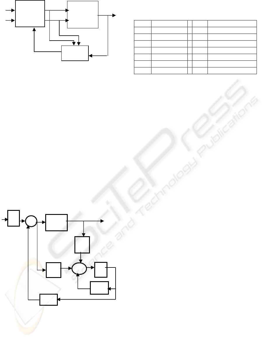
Figure 4: Control with ship speed observer.
The structure a luenberger observer is given by
(Stoorvogel , Saberi and Chen 1994). ( Mieczarski,
1988):
⎪
⎩
⎪
⎨
⎧
=
−++=
x
ˆ
Cy
ˆ
)y
ˆ
y(LBux
ˆ
Ax
ˆ
s
(24)
where:
x
ˆ
is the output vector of the state observer
L is the observer gain
This structure can be written in this form:
s
LyBux
ˆ
A
ˆ
x
ˆ
++=
(25)
with :
LCAA
ˆ
−=
To have an asymptotic convergence of the
observed state towards the real state, it is necessary
to choose the gain L such that the matrix
)LCA(
−
has negative real part eigen values. The control law
using the state observer is presented as follows:
)t(x
ˆ
K)t(Fe)t(u
−
=
(26)
Figure 5: Observed state feedback control.
5 SIMULATION RESULTS
SECOND SECTION
A digital simulation of the proposed control law
with the designed state observer has been carried out
with on the ship electric propulsion system using the
following characteristics.
Para. value Par. Value
ρ 1025 Kg/m
3
Q
n
3.1480010
5
Nm
D 5.9 m T
n
3.82000 10
5
N
m 20690000 kg, Q
f
0.382 10
5
t 0.178 T
ext.
-1.8*0.1*10^5N
w 0.2304 s
1
0.075
a 1.54 10
6
s
2
0.1375
r2 1.1 r
1
0.5
The resolution of the Riccati equation (23) yields to:
• The optimal control gain:
⎥
⎦
⎤
⎢
⎣
⎡
−
=
0030.07618.90467.01064.0
0002.03830.100520.09807.0
K
• The observer gain:
⎥
⎥
⎥
⎥
⎦
⎤
⎢
⎢
⎢
⎢
⎣
⎡
−−
=
9.13623.10
6.61.0
6.3396.10
8.19645.3
L
The resolution of the equation (22) gives the
reference gain:
⎥
⎦
⎤
⎢
⎣
⎡
−
=
3032.261064.0
05078.39963.0
F
For the designed control, we impose i
dref
=0, so that
the electromagnetic torque C
e
will be proportional to
i
q
.
In order to control the ship speed v it is
necessary to change the motor speed n through the
stator component i
q
which modify the
electromagnetic torque ( Dallagi and Nejim, 2005 ).
The performances of the proposed strategy
control law are depicted in the figures 6, 7, 8 and 9.
The ship speed is needed to reach the reference
speed value V
ref
=8m/s in the interval [0 150s] and
V
ref
=10m/s in the interval [150 300s].
It appears from figure 6, that the proposed
control law allows a convergence towards the
desired value of the ship speed v.
The figure 7 shows the behavior of the motor speed.
It's clear that the ship speed changes where the
variation of the propeller speed changes.
Furthermore, we impose i
dref
=0, so the
electromagnetic torque becomes proportional to
statoric current i
q
.
In order to control the motor speed n, one modify the
electromagnetic torque C
em
by changing the stator
current i
q
through the regulation of the voltage
component v
q.
(
Grellet and Clerc,2000).
v
ref
Electric
Motor
+ Ship
Optimal
Control
i
dref
Observer
x
ˆ
Vd Vq
id, n
v
∫
A-LC
-K
B
+
System
L
+
e(t)
u(t)
y
s
(t)
x
ˆ
F
ICINCO 2007 - International Conference on Informatics in Control, Automation and Robotics
300
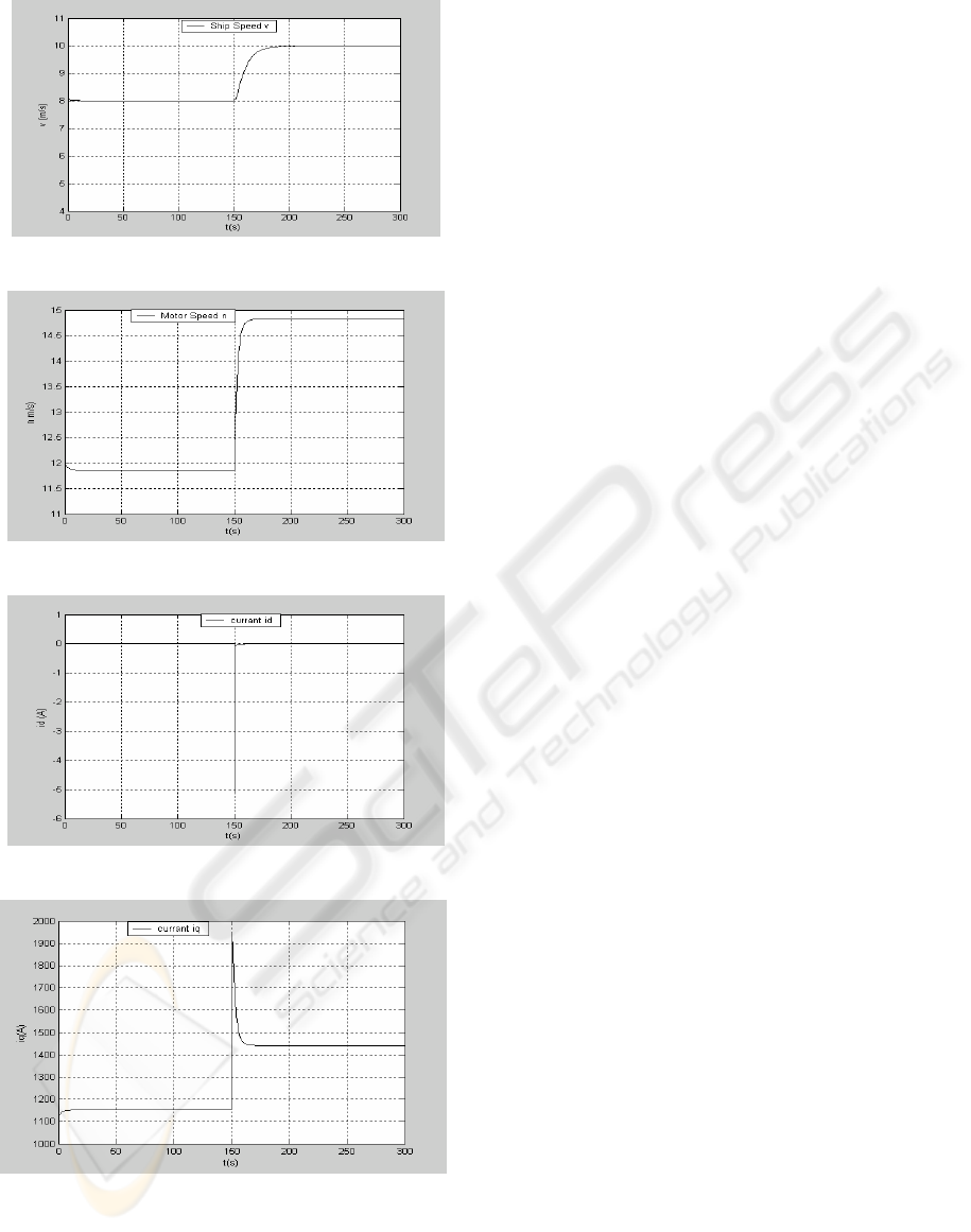
Figure 6: Ship Speed.
Figure 7: Motor Speed.
Figure 8: Current id.
Figure 9: Current iq.
6 CONCLUSIONS
In this paper we have proposed an optimal control
law using a Luenberger sate observer to control the
ship speed.
The designed observer is used to reconstruct the
ship speed in order to complete the control strategy.
It has been shown from the simulated results that the
proposed estimated state feedback optimal control
permits the regulation of the ship speed which
converges exactly to the imposed reference.
REFERENCES
Dallagi, H., Nejim, S., 2004. Modélisation et simulation
d’un système de propulsion diesel-électrique de
Navire. In 3ème Conférence Internationale, JTEA,
Tunisie.
Grellet,Guy., Clerc, Guy., 2000. Actionneurs Electriques,
principe modèle et commande. In Editions Eyrolles.
Dallagi, H,. Nejim, S., 2006. Conception d’un programme
de prédiction et d’estimation de la puissance
propulsive des navires à propulsion électrique. In 4ème
Conférence Internationale, JTEA, Tunisie.
Izadi-Zamanabadi, R, Blanke, M., Katebi, S.2001. Cheap
diagnostisis using structural modelling and fuzzy-logic
based detection.
Fosen, T.I Blanke, M. 2000. Nonlinear output feedback
control of underwater vehicle propellers usingfeedbak
from estimated axial flow velocity. In IEEE journal of
oceanic engineering, vol 25, no2
Guo Y, Zheng, Y Wang B Shen A. 2005. Design of ship
electric propulsion simulation system. In Proceeding
of the fourth international conference on machine
learning and cybernetics. Guangzhou.
Devauchell, P., 1986 “Dynamique du Navire. In Masson,
Paris.
Toscano, R,. 2005. Commande et diagnostic des système
dynamique,. In Elipses Edition , Paris.
Corriou J.P,. 1996. Commande des procédés. In
Techniques et documentations, Paris.
Rachid, A,. Mehdi, D,. 1997. Réalisation réduction et
commande des systèmes linéaire. In édition technip
Paris.
Stoorvogel , A.A., Saberi, A., Chen, B.M., 1994. A
Reduced order observer base control design for
optimization. In IEEE transaction automatic
Mieczarski.,W., 1988. Very fast linear and nonlinear
observer. In int. J. control.
Dallagi, H., Nejim,S., 2005. Modélisation and Simulation
of an Electric Drive for a Two Propeller Ship. In 17
ème
Congrès Mondial IMACS, Calcul Scientifique,
Mathématiques Appliquées et Simulation, Paris,
France.
Doutreleau, Y., Codier ,.S. 2001. Les problèmes des
navires à grande vitesse. In J.T .
Snitchler G., Gambe B.B., Kalsi S., Ige, S.O. 2006. The
stats of HTS ship propulsion motor developments. In
IEEE Transaction on applied superconductivity.
OBSERVER BASED OPTIMAL CONTROL OF SHIP ELECTRIC PROPULSION SYSTEM
301

Kalsi S, Gambe B.B, Snitchler G,. 2005. The performance
of 5Mw high temperature superconductor ship
propulsion motor. In IEEE Transaction on applied
superconductivity, vol, 15, n°2
Dallagi, H., Nejim, S., 2005. Optimization of an
integrated power system of an electric ship. In
International Conference on ship propulsion and
railway traction systems, Bologna–Italy,
Zimin, W.Vilar., Roger, A.Douglas., 2005. Effectiveness
of generator Strategies on meeting pulsed load
requirements in ship electric system. In IEEE electric
ship technologies symposium.
Izadi-Zamanabadi R. Blank, M,. A ship propulsion
system model for fault-tolerant Control,” Department
of control Engineering Aalborg university,
Dennemark.
Gillmer T.C., Jonson B,. 1982. Propulsive force and
propulsion system. In Naval Institue Press, Annapolis,
Maryland.
Blanke, M., Izadi-Zamanabadi, R,. 1998. Reconfigurable
control of a ship propulsion plant. In Control
Applications in Marine Systems, CAMS, Fukuoka,
Japan.
Lootsma, T.F., Zamanabadi, R.I., Nijmeijer, H., 2002. A
Geometric approach to diagnosis applied to a ship
propulsion problem. In 15
th
Triennal World Congress,
IFAC , Barcelona, Spain.
Steinar J.Dale., 2005. Ship power system testing and
simulation. In IEEE Electric ship technology
symposium.
Rudly, Limpaecher., 2000. Novel converters for electric
ship propulsion system and shipboard power
distribution. In IEEE transactions on energy
conversion.
ICINCO 2007 - International Conference on Informatics in Control, Automation and Robotics
302
