
AN IMPLEMENTATION OF HIGH AVAILABILITY IN
NETWORKED ROBOTIC SYSTEMS
Florin Daniel Anton, Theodor Borangiu and Silvia Anton
University Politehnica of Bucharest, Dept. of Automation and Applied Informatics
313, Spl. Independentei sector 6, RO-060032, Bucharest
Keywords: Networked robotics, high availability, fault tolerant systems, resource monitoring, resource control.
Abstract: In today’s complex enterprise environments, providing continuous service for applications is a key
component of a successful robotized implementing of manufacturing. High availability (HA) is one of the
components contributing to continuous service provision for applications, by masking or eliminating both
planned and unplanned systems and application downtime. This is achieved through the elimination of
hardware and software single points of failure (SPOF). A high availability solution will ensure that the
failure of any component of the solution - either hardware, software or system management, will not cause
the application and its data to become permanently unavailable. High availability solutions should eliminate
single points of failure through appropriate design, planning, hardware selection, software configuring,
application control, carefully environment control and change management discipline. In short, one can
define high availability as the process of ensuring an application is available for use by duplicating and/or
sharing hardware resources managed by a specialized software component. A high availability solution in
robotized manufacturing provides automated failure detection, diagnosis, application recovery, and node
(robot controller) re integration. The paper discusses the implementing of a high availability solution in a
robotized manufacturing line.
1 HIGH AVAILABILITY VERSUS
FAULT TOLERANCE
Based on the response time and response action to
system detected failures, clusters and systems can be
generally classified as:
• Fau
lt-tolerant
• High
availability
1.1 Fault-tolerant Systems
The systems provided with fault tolerance are
designed to operate virtually without interruption,
regardless of the failure that may occur (except
perhaps for a complete site going down due to a
natural disaster). In such systems
all
components are
at least duplicated for both software and hardware.
This means that all components, CPUs, memory,
Ethernet cards
, serial lines and disks have a special
design and provide continuous service, even if one
sub-component fails. Only special software solutions
will run on fault tolerant hardware.
Such systems are very expensive and extremely
sp
ecialized. Implementing a fault tolerant solution
requires a lot of effort and a high degree of
customization for all system components.
For environments where no dow
ntime is
acceptable (life critical systems), fault-tolerant
equipment and solutions are required.
1.2 High Availability Systems
The systems configured for high availability are a
combination of hardware and software components
configured to work together to ensure automated
recovery in case of failure with a minimal acceptable
downtime.
In such industrial systems, th
e software involved
detects problems in the robotized environment
(production line, flexible manufacturing cell), and
manages application survivability by restarting it on
the same or on another available robot controller.
Thus, it is very important to eliminate all single
poi
nts of failure in the manufacturing environment.
For example, if a robot controller has only one
network interface (connection), a second network
131
Daniel Anton F., Borangiu T. and Anton S. (2007).
AN IMPLEMENTATION OF HIGH AVAILABILITY IN NETWORKED ROBOTIC SYSTEMS.
In Proceedings of the Fourth International Conference on Informatics in Control, Automation and Robotics, pages 131-136
DOI: 10.5220/0001647901310136
Copyright
c
SciTePress
interface (connection) should be provided in the
same node to take over in case the primary interface
providing the service fails.
Another important issue is to protect the data by
mirroring and placing it on shared disk areas
accessible from any machine in the cluster, directly
or using the local area network.
2 HIGH AVAILABILITY TERMS
AND CONCEPTS
For the purpose of designing and implementing a
high-availability solution for networked robotic
stations integrated in a manufacturing environment,
the following terminology and concepts are
introduced:
RMC: The Resource Monitoring and Control
(RMC) is a function giving one the ability to
monitor the state of system resources and respond
when predefined thresholds are crossed, so that
many routine tasks can be automatically performed.
Cluster: Loosely-coupled collection of
independent systems (nodes – in this case robot
controllers) organized into a network for the purpose
of sharing resources and communicating with each
other. A cluster defines relationships among
cooperating systems, where peer cluster nodes
provide the services offered by a cluster node should
that node be unable to do so.
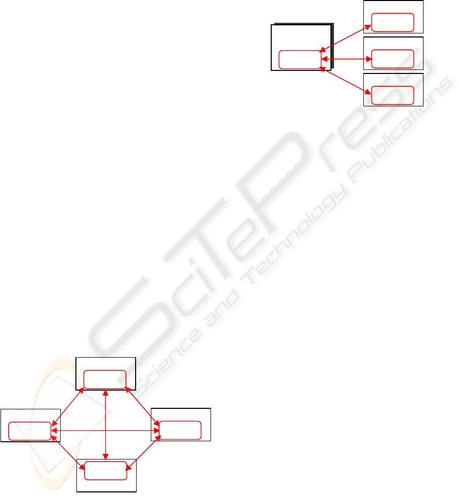
There are two types of high availability clusters:
• Peer domain
• Managed domain
The general difference between these types of
clusters is the relationship between the nodes.
Figure 1: Peer domain cluster topology.
In a peer domain (Figure 1), all nodes are
considered equal and any node can monitor and
control (or be monitored and controlled) by any
other node (Harris et. al., 2004).
In a management domain (Figure 2), a
management node is aware of all nodes it is
managing and all managed nodes are aware of their
management server, but the nodes themselves know
nothing about each other.
Cluster Node 1
Figure 2: Managed domain cluster topology.
Node: A robot controller that is defined as part
of a cluster. Each node has a collection of resources
(disks, file systems, IP addresses, and applications)
that can be transferred to another node in the cluster
in case the node or a component fails.
Clients: A client is a system that can access the
application running on the cluster nodes over a local
area network. Clients run a client application that
connects to the server (node) where the application
runs.
Resources: Logical components or entities that
are being made highly available (for example, file
systems, raw devices, applications, etc.) by being
moved from one node to another. All the resources
that together form a highly available application or
service are grouped in one resource group (RG).
Group Leader: The node with the highest IP as
defined in one of the cluster networks (the first
communication network available), that acts as the
central repository for all topology and group data
coming from the applications which monitor the
state of the cluster.
SPOF: A single point of failure (SPOF) is any
individual component integrated in a cluster which,
in case of failure, renders the application unavailable
for end users. Good design will remove single points
of failure in the cluster - nodes, storage, networks.
The implementation described here manages such
single points of failure, as well as the resources
required by the application.
The most important unit of a high availability
cluster is the Resource Monitoring and Control
(RMC) function, which monitors resources (selected
by the user in concordance with the application) and
performs actions in response to a defined condition.
Management
server
RM
C
RM
C
Cluster Node 2
RM
C
Cluster Node 3
RM
C
Cluster Node 1
Cluster Node 2
RM
C
RM
C
Cluster Node 4
RM
C
Cluster Node 3
RM
C
ICINCO 2007 - International Conference on Informatics in Control, Automation and Robotics
132
RMC Process
RMC Command:
lsrsrc, mkrsrc ,…
RM
C
API
(
local or remote
)
RMgr Api
S
DK
V
+
Audit
Logging
RMgr Api
S
DK
V
+
Filesystem
Local FS
NFS
RMgr Api
S
DK
V
+
EventResponse
Condition
EventResponse
Association
RMgr Api
S
DK
V
+
Host
Host (Controller)
Program
Ethernet Device
RS232 Device
Resource
Managers
Configuration database
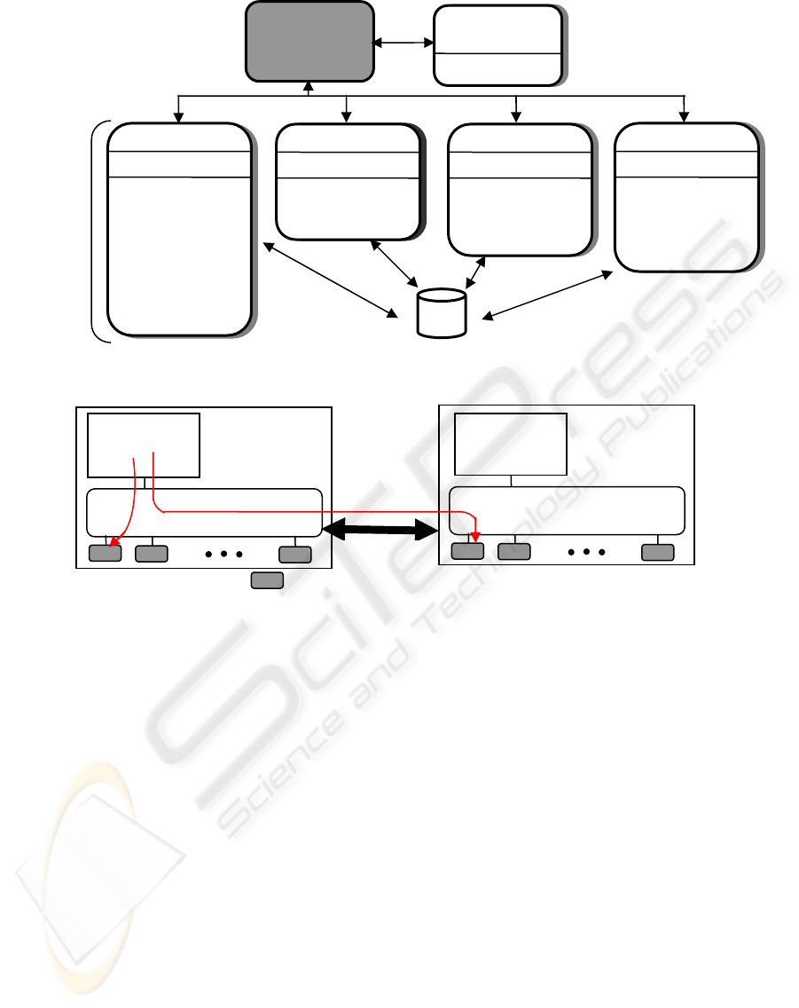
Figure 3: The structure of the RMC subsystem.
N
ode 1
N
ode 2
R
esou
r
ce
a
n
d
R
esou
r
se
c
l
asses
RMC client
(CLI)
RMC client
(CLI)
RMC subsyste
m
Netwo
r
k
A B
RMC subsyste
m
Figure 4: The relationship between RMC Clients (CLI) and RMC subsystems.
3 RMC ARCHITECTURE AND
COMPONENTS DESIGN
The design of RMC architecture is presented for a
multiple-resource production control system. The set
of resources is represented by the command, control,
communication, and operational components of
networked robot controllers and robot terminals
integrated in the manufacturing cell.
The RMC subsystem to be defined is a generic
cluster component that provides a scalable and
reliable backbone to its clients with an interface to
resources.
The RMC has no knowledge of resource
implementation, characteristics or features. The
RMC subsystem therefore delegates to resource
managers the actual execution of the actions the
clients ask to perform (see Figure 3).
The RMC subsystem and RMC clients need not
be in the same node; RMC provides a distributed
service to its clients. The RMC clients can connect
to the RMC process either locally or remotely using
the RMC API i.e. Resource Monitoring and Control
Application user Interface (Matsubara et al., 2002).
Similarly, the RMC subsystem interacting with
Resource Managers need not be in the same node. If
they are on different nodes, the RMC subsystem will
interact with local RMC subsystems located on the
same node as the resource managers; then the local
RMC process will forward the requests. Each
resource manager is instantiated as one process. To
avoid the multiplication of processes, a resource
manager can handle several resource classes.
The commands of the Command Line Interface
are V+ programs (V+ is the robot programming
environment); the end-user can check and use them
as samples for writing his own commands.
A RMC command line client can access all the
resources within a cluster locally (A) and remotely
(B) located (Figure 4). The RMC command line
interface is comprised of more than 50 commands
(V+ programs): some components, such as the Audit
resource manager, have only two commands, while
AN IMPLEMENTATION OF HIGH AVAILABILITY IN NETWORKED ROBOTIC SYSTEMS
133
others, such as Event Response resource manager,
have 15 commands.
Each resource manager is the interface between the
it resource manager)
1. on resource manager).
2. ents (Event Response resource
4. e manager, File
esponse resource manager (ERRM)
pla
resource manager provides
a s
dition composed of a resource
• composed of zero or
• ore responses with a
condition and activate the association.
are tatus of
res
Co being
used and with
are
4 SOLUTION IMPLEMENTING
FOR NETWORKED ROBOTS
In o of
robo d,
RMC subsystem and a specific aspect of the Adept
Windows operating system instance it controls. All
resource managers have the same architecture and
interact with the other RMC components. However,
due to their specific nature, they have different usage
for the end user. The resource managers are
categorized into four groups:
1. Logging and debugging (Aud
The Audit Log resource manager is used by other
RMC components to log information about their
actions, errors, and so on.
Configuration (configurati
The configuration resource manager is used by
the system administrator to configure the system
in a Peer Domain cluster. It is not used when
RMC is configured in Standalone or Management
Domain nodes.
Reacting to ev
manager). The Event Response resource manager
is the only resource manager that is directly used
in normal operation conditions.
Data monitoring (Host resourc
system resource manager). This group contains
the file system resource manager and the Host
resource manager. They can be seen by the end
user as the containers of the objects and variables
to monitor.
The Event R
ys the most important role to monitor systems
using RMC and provides the system administrator
with the ability to define a set of conditions to
monitor in the various nodes of the cluster, and to
define actions to take in response to these events
(Lascu, 2005). The conditions are applied to
dynamic properties of any resources of any resource
manager in the cluster.
The Event Response
imple automation mechanism for implementing
event driven actions. Basically, one can do the
following actions:
• Define a con
property to be monitored and an expression that
is evaluated periodically.
Define a response that is
several actions that consist of a command to be
run and controls, such as to when and how the
command is to be run.
Associate one or m
ERRM evaluates the defined conditions which
logical expressions based on the s
ources attributes; if the conditions are true a
response is executed.
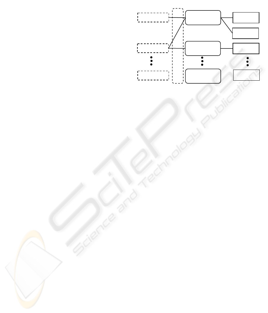
Figure 5: Conditions, responses and actions.
nditions and responses can exist without
nothing related to each other. Actions
part of responses and only defined relative to
them. Although it is possible that multiple responses
have an action using the same name, these actions
do not refer to the same object.
To start observing the monitored resource, a
condition must be associated with at least one
res
ponse. You can associate a condition with
multiple responses.
Figure 5 illustrates the relationship between the
conditions, the responses, and the actions. In this
sch
eme, there are three associations (A, B, and C).
The association has no name. The labels A, B,
and C are for reference purposes. To refer to the
spe
cific association, you have to specify the
condition name and the response name that make the
association. For example, you have to specify the
condition 1 and the response 1 to refer to the
association A. Also, it must be clear that the same
action name (in this example, action a) can be used
in multiple responses, but these actions are different
objects.
rder to implement the solution on a network
t controllers, first a shared storage is neede
which must be reached by any controller from the
cluster.
Association
Condition 1
Response 1
Action a
Action b
Action a
Action n
Condition 2 Response 2
A
B
C
Condition N
R
esponse M
ICINCO 2007 - International Conference on Informatics in Control, Automation and Robotics
134
Quorum
Shared storage
NFS
Network Switch
Network Switch
Fiber Channel HBA
Network interface
Network interface
NFS Cluster
Node 2
Fiber Channel HBA
Network interface
Network interface
NFS Cluster
Node 1
Network Switch
Fiber Channel HBAFiber Channel HBA
SAN Switch
RSA 232
RSA 232 RSA 232
RSA 232
SAN Switch
Network interface
Fabrication Cluster
Robot Controller 1
RSA 232
RSA 232
Network interface
Fabrication Cluster
Robot Controller 2
RSA 232
RSA 232
Network interface
Fabrication Cluster
Robot Controller n
RSA 232
RSA 232
MANUFACTURING STRUCTURE
(
Cell, Line, …
)
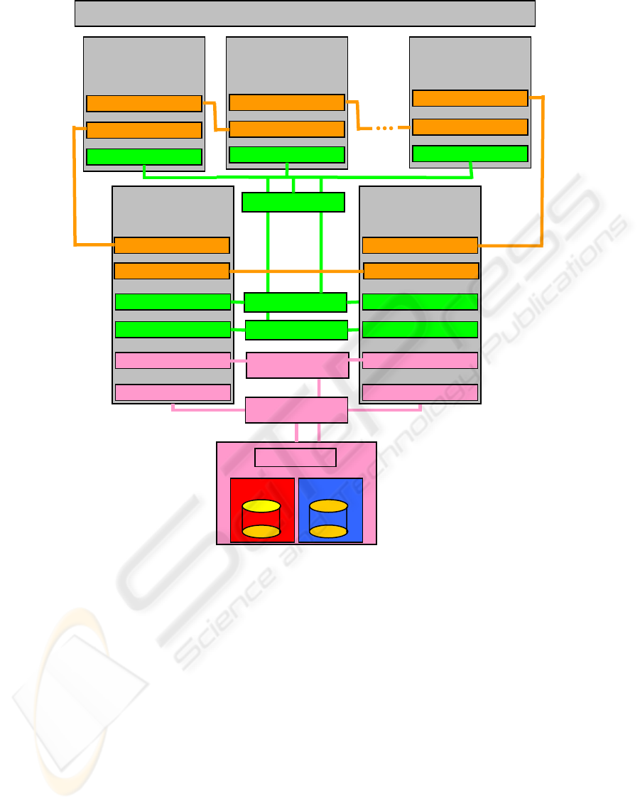
Figure 6: Implementing the high availability solution for the networked robotic system.
The file system from the storage is limited to
NFS (network file system) by the operating system
of the robot controllers (Adept Windows). Five
Adept robot manipulators were considered, each one
having its own multitasking controller.
For the proposed architecture, there is no option
to use a directly connected shared storage, because
Adept robot controllers do not support a Fiber
Channel Host Bus Adapter (HBA). Also the storage
must be high available, because it is a single point of
failure for the Fabrication Cluster (FC).
Due to these constraints, the solution was to use
a High Availability cluster to provide the shared
storage option (NFS Cluster), and another cluster
composed by Adept Controllers which will use the
NFS service provided by the NFS Cluster (Figure 6).
The NFS cluster is composed by two identical
IBM xSeries 345 servers (2 processors at 2.4 GHz,
1GB RAM, and 75GB Disk space, two RSA 232
lines, two Network adapters, and two Fiber Channel
HBA), and a DS4100 storage. The storage contains a
volume named Quorum which is used by the NFS
cluster for communication between nodes, and a
NFS volume which is exported by the NFS service
which runs in the NFS cluster. The servers have
each interface (network, serial, and HBA) duplicated
to assure redundancy (Anton et al., 2006; Borangiu
et al., 2006).
In order to detect the malfunctions of the NFS
cluster, the servers send and receive status packets to
ensure that the communication is established.
There are three communication routes: the first
route is the Ethernet network, the second is the
Quorum volume and the last communication route is
the serial line. If the NFS cluster detects a
malfunction of one of the nodes and if this node was
AN IMPLEMENTATION OF HIGH AVAILABILITY IN NETWORKED ROBOTIC SYSTEMS
135

the node which served the NFS service the cluster is
reconfiguring as follows:
1. The server which is still running writes in the
Quorum volume which is taking the functions of
the NFS server, then
2. Mounts the NFS volume, then
3. Takes the IP of the other server and
4. Starts the NFS service.
In this mode the Fabrication Cluster is not
aware about the problems from the NFS cluster,
because the NFS file system is further available.
The Fabrication Cluster can be composed by at
least two robot controllers (nodes) – group leader
and a common node. The nodes have resources like:
robot manipulators (with attributes like: collision
detection, current robot position, etc...), serial lines,
Ethernet adapter, variables, programs, NFS file
system. The NFS file system is used to store
programs, log files and status files. The programs
are stored on NFS to make them available to all
controllers, the log files are used to discover the
causes of failure and the status files are used to
know the last state of a controller.
In the event of a node failure, the production
flow is interrupted. In this case, if there is a
connection between the affected node and the group
leader, the leader will be informed and the GL takes
the necessary actions to remove the node from the
cluster. The GL also reconfigures the cluster so the
fabrication process will continue. For example if one
node cluster fails in a three-node cluster, the
operations this node was doing will be reassigned to
one of the remaining nodes.
The communication paths in the multiple-robot
system are: the Ethernet network and the serial
network. The serial network is the last resort for
communication due to the low speed and also to the
fact that it uses a set of Adept controllers to reach
the destination. In this case the ring network will be
down if more than one node will fail.
5 CONCLUSIONS
The high availability solution presented in this paper
is worth to be considered in environments where the
production structure has the possibility to
reconfigure, and where the manufacturing must
assure a continuous production flow at batch level
(job shop flow).
There are also some drawbacks like the need of
an additional NFS cluster. The spatial layout and
configuring of robots must be done such that one
robot will be able to take the functions of another
robot in case of failure. If this involves common
workspaces, programming must be made with much
care using robot synchronizations and monitoring
continuously the current position of the manipulator.
The advantages of the proposed solution are that
the structure provides a high availability robotized
work structure with a insignificant downtime.
The solution is tested on a four-robot assembly
cell located in the Robotics and IA Laboratory of the
University Politehnica of Bucharest. The cell also
includes a CNC milling machine and one Automatic
Storage and Retrieval System, for raw material
feeding and finite products storage.
During the tests the robot network has detected a
number of errors (end-effector collision with parts,
communication errors, power failure, etc.) The GL
has evaluated the particular situation, the network
was reconfigured and the abandoned applications
were restarted in a time between 0.2 and 3 seconds.
The most unfavourable situation is when a robot
manipulator is down; in this case the down time is
greater because the application which was executed
on that controller must be transferred, reconfigured
and restarted on another controller. Also if the
controller still runs properly it will become group
leader to facilitate the job of the previous GL.
In some situations the solution could be
considered as a fault tolerant system due to the fact
that even if a robot controller failed, the production
continued in normal conditions.
REFERENCES
Anton F., D., Borangiu, Th., Tunaru, S., Dogar, A., and S.
Gheorghiu, 2006. Remote Monitoring and Control of a
Robotized Fault Tolerant Workcell, Proc. of the 12
th
IFAC Sympos. on Information Control Problems in
Manufacturing INCOM'06, Elsevier.
Borangiu, Th., Anton F., D., Tunaru, S., and A. Dogar,
2006. A Holonic Fault Tolerant Manufacturing
Platform with Multiple Robots, Proc. of 15
th
Int.
Workshop on Robotics in Alpe-Adria-Danube Region
RAAD 2006.
Lascu, O. et al, 2005. Implementing High Availability
Cluster Multi-Processing (HACMP) Cookbook, IBM
Int. Technical Support Organization, 1
st
Edition.
Harris, N., Armingaud, F., Belardi, M., Hunt, C., Lima,
M., Malchisky Jr., W., Ruibal, J., R. and J. Taylor,
2004. Linux Handbook: A guide to IBM Linux
Solutions and Resources, IBM Int. Technical Support
Organization, 2
nd
Edition.
Matsubara, K., Blanchard, B., Nutt, P., Tokuyama, M.,
and T. Niijima, 2002. A practical guide for Resource
Monitoring and Control (RMC), IBM Int. Technical
Support Organization, 1
st
Edition.
ICINCO 2007 - International Conference on Informatics in Control, Automation and Robotics
136
