
BICYCLE WHEEL WOBBLE
A Case Study in Dynamics
John V. Ringwood and Ruijuan Feng
Dept. of Electronic Engineering
NUI Maynooth
County Kildare, Ireland
Keywords:
Bicycle, dynamics, wheel wobble, instability.
Abstract:
This paper examines reasons why wheel wobble occurs in common production bicycles. In particular, the
effects of frame size, rider position and riding style are examined with reference to a range of mathematical
models of bicycles which are available in the published literature. Much of the motivation for this work comes
from the personal cycling experience of one of the authors and the difficulty in resolving the true cause of
wheel wobble from the wide range of advice offered of a variety of cycling experts. It is hoped that recourse to
a mathematical analysis will give objective direction as to how wheel wobble can be alleviated through rider
intervention.
1 INTRODUCTION
Since 1869 (Rankine, 1869), engineers have been in-
trigued by the dynamics of the simple bicycle. In re-
cent years, there has been somewhat of a resurgence
of interest with the appearance of a number of ex-
cellent review papers, such as (Astrom et al., 2005;
Limebeer and Sharp, 2006), with reference to almost
170 technical works on the subject. From a dynamics
perspective, the study of the bicycle is attractive for
many reasons:
• The bicycle is ubiquitous in our lives as a device
for commuting, recreation and sport,
• It permits various levels of complexity of anal-
ysis, from an interesting lumped-parameter sys-
tem with non-minimum phase characteristics to
a complex system described by a distributed-
parameter model,
• Since bicycles are relatively easy to construct,
they can be used as mechanical engineering
testbeds, with a range of configurations limited
only by imagination (Klein, 1989), and
• With the drive towards decreased weight and im-
proved performance, commercial developers in
bicycle and motorsport have a great interest in
the dynamics of single-track vehicles (Beghi and
Frezza, 2006; Hauser and Saccon, 2006).
The motivation for the current study comes from
the modest, but important, aspiration of trying to stay
upright on a road (racing) bicycle during high-speed
descents. While it might be true to say that the aspi-
rant in question (one of the authors on this paper!) is
not the most accomplished/confident bike rider, some
contribution by the bicycle dynamics to the rider’s
problem is likely, since:
• The author in question has consistently experi-
enced speed wobble (sometimes called ‘shimmy’
(Brandt, 2005)) with two well-known production
bicycles, but not with a third, and
• The bicycles which exhibited wheel wobble have
been successfully ridden by many other cyclists
(including Lance Armstrong in his 2003 Tour de
France success) with no evidence of wheel wob-
ble.
Wheel wobble is a spontaneous steering oscillation
of the front wheel, usually building as the speed
approaches a certain threshold. Many theories and
myths exist in relation to wheel wobble, including:
1. Wheel wobble is a function of the natural bicycle
dynamics, not rider induced i.e. it is inherent to
the geometry and elasticity of the bicycle frame
(Brandt, 2005).
2. The common rider response of gripping the han-
dlebars tighter only serves to increase the oscilla-
tion.
3. Shimmy can be minimised by keeping the knee
against the crossbar (increases damping).
238
V. Ringwood J. and Feng R. (2007).
BICYCLE WHEEL WOBBLE - A Case Study in Dynamics.
In Proceedings of the Fourth International Conference on Informatics in Control, Automation and Robotics, pages 238-243
DOI: 10.5220/0001643302380243
Copyright
c
SciTePress
4. Shimmy is less prevalent in bicycles which have a
longer trail (see model in Section 2).
5. Shimmy is more likely in bicycles with longer
frames and higher saddles.
6. Weight distribution has no effect on shimmy al-
though where that weight contacts the frame does
(Brandt, 2005).
7. Shimmy is due to loose bearings or eccentrics
in the rotational masses (most common reason
given, but refuted my many experts).
It is also the experience of the author that shimmy
tends to accompanying braking - release of brakes ap-
pears to diminish the wobble oscillation amplitude or
remove it altogether.
The objective of this study is to examine the range
of possible reasons from a pragmatic dynamical sys-
tems perspective to see if the root cause of wheel wob-
ble can be identified and to look for any rider interven-
tions (such as weight distribution, braking protocol,
etc) which may help to alleviate the symptom.
2 BICYCLE MODEL
The model used in this study is based on that pre-
sented in (Astrom et al., 2005). Assumptions under
which the model is developed include:
• The bicycle consists of four rigid parts: Frame (in-
cluding rider), front fork with handlebars and two
wheels.
• The influence of other moving parts, such as ped-
als, chain and brakes on the dynamics is ne-
glected.
• The forward velocity of the bicycle,V, is constant.
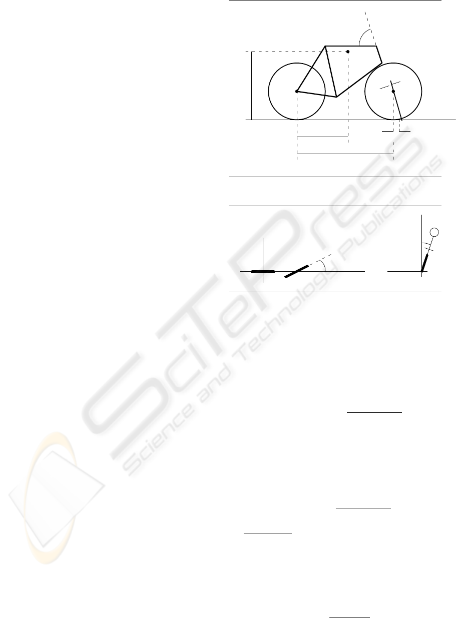
Figs.1 and 2 show the representations of the parame-
ters and variables of the system (respectively), with:
O being the centre of mass (including rider)
c is known as the trail
λ is the head angle
φ is the lean angle
δ is the steering angle
The front fork is key to the ability of a bicycle to
self-stabilize and the key relationship is that between
φ and δ. For small angles, the front fork roll angle is:
φ
f
= φ− δcos(λ) (1)
and the effective front fork steering angle is:
δ
f
= δsin(λ) (2)
.
.
.
.
.
.
.
.
.
.
.
.
.
.
.
.
.
.
.
.
.
.
.
.
.
.
.
.
-
c
1
)
R
O
6
?
-
-
h
a
b
λ
Figure 1: Bicycle parameters.
-
6
δ
x
y
6
y
z
φ
Steering angle, δ
Lean
angle,
φ
Figure 2: Bicycle variables.
A static torque balance is used to model the front fork,
neglecting dynamics and gyroscopic effects. If N
f
and F
f
are the vertical and horizontal forces acting
on the front wheel at the ground contact, then:
N
f
= a m g/b (3)
where m is the combined mass of rider and frame, and
F
f
= amV
2
δ
f
/b
2
=
a m V
2
sin(λ)
b
2
δ (4)
The static torque balance for the front fork, assuming
negligible mass of the front fork assembly, is:
T − (F
f
+ N
f
φ
f
)c sin(λ) (5)
where T is the external torque applied to the handle-
bar. Using (1), (2), (3) and (4), (5) reduces to:
T −
a c m g sin(λ)
b
φ−
a c m sin(λ)
b
2
(V
2
sin(λ) − b gcos(λ))δ = 0
where g is the acceleration due to gravity. The torque
balance can be rewritten as:
δ = k
1
(V)T − k
2
(V)φ (6)
which demonstrates negative feedback (self-
stabilization) between φ and δ if k
2
is +ve, or
V >
p
b g cot(λ) (7)
BICYCLE WHEEL WOBBLE - A Case Study in Dynamics
239
where:
k
1
(V) =
b
2
(V
2
sin(λ) − b g cos(λ))m a c sin(λ)
(8)
and
k
2
(V) =
b g
V
2
sin(λ) − b g cos(λ)
(9)
Note that the center of mass of the frame is shifted
when the front wheel is turned, giving the torque:
T
δ
= −
m g a c sin(λ)
b
δ (10)
An overall angular momentum balance for the frame
can now be constructed as:
J
d
2
φ
dt
2
−mghφ =
DVsin(λ)
b
dδ
dt
+
m(V
2
h− acg)sin(λ)
b
δ
(11)
where J is the moment of inertia of the bicycle with
respect to the x-axis and D is the inertia product with
respect to the x − z axes (see Figs.1 and 2). Finally,
inserting (6) into the momentum balance gives:
J
d
2
φ
dt
2
+
DVg
V
2
sin(λ) − bgcos(λ)
dφ
dt
+
mg
2
(bhcos(λ) − acsin(λ))
V
2
sin(λ) − bgcos(λ)
φ
=
DVb
acm(V
2
sin(λ) − bgcos(λ))
dT
dt
+
b(V
2
h− acg)
ac(V
2
sin(λ) − bgcos(λ))
T (12)
The system poles can be evaluated as:
p
1,2
=
−DVg
K
±
r
d
2
V
2
g
2
K
2
1
−
4Jmg
2
(K
2
)
K
1
2J
(13)
or
p
1,2
=
−mahVg±
p
(mahVg)
2
− 4m
2
g
2
h
2
K
1
(K
2
)
2mh
2
K
1
(14)
where
K
1
= V
2
sin(λ) − bgcos(λ) (15)
and
K
2
= bhcos(λ) − acsin(λ) (16)
3 MODEL PARAMETERIZATION
In this section, the model parameters will be deter-
mined for a (2003) Trek 5200. The manufacturer pro-
vides a table of some of the critical model dimensions,
as they vary with frame size, as: We can provide a
Table 1: Variation in bicycle parameters with frame size.
Frame size b(m) R λ (deg)
50 0.979 0.0045 72
52 0.981 0.0045 72.5
54 0.985 0.0045 73
56 0.996 0.0045 73.8
58 0.996 0.0045 73.8
60 1.004 0.0045 74
62 1.008 0.0045 74
simple transformation of fork rake (given by the man-
ufacturer), R, to trail (used in the model), c, via some
simple geometry as:
c =
r− R/cos(λ)
tan(λ)
(17)
where r = 0.35m for a 700c wheel. The remaining
model parameters, h and a, which define the vertical
and horizontal position (respectively) of the centre of
mass, O, must be determined by experiment and are
addressed in Sections 3.1 and 3.2 respectively. While
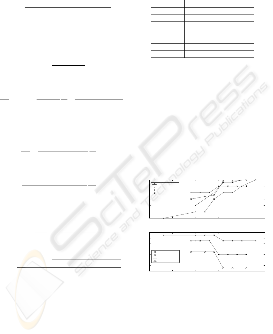
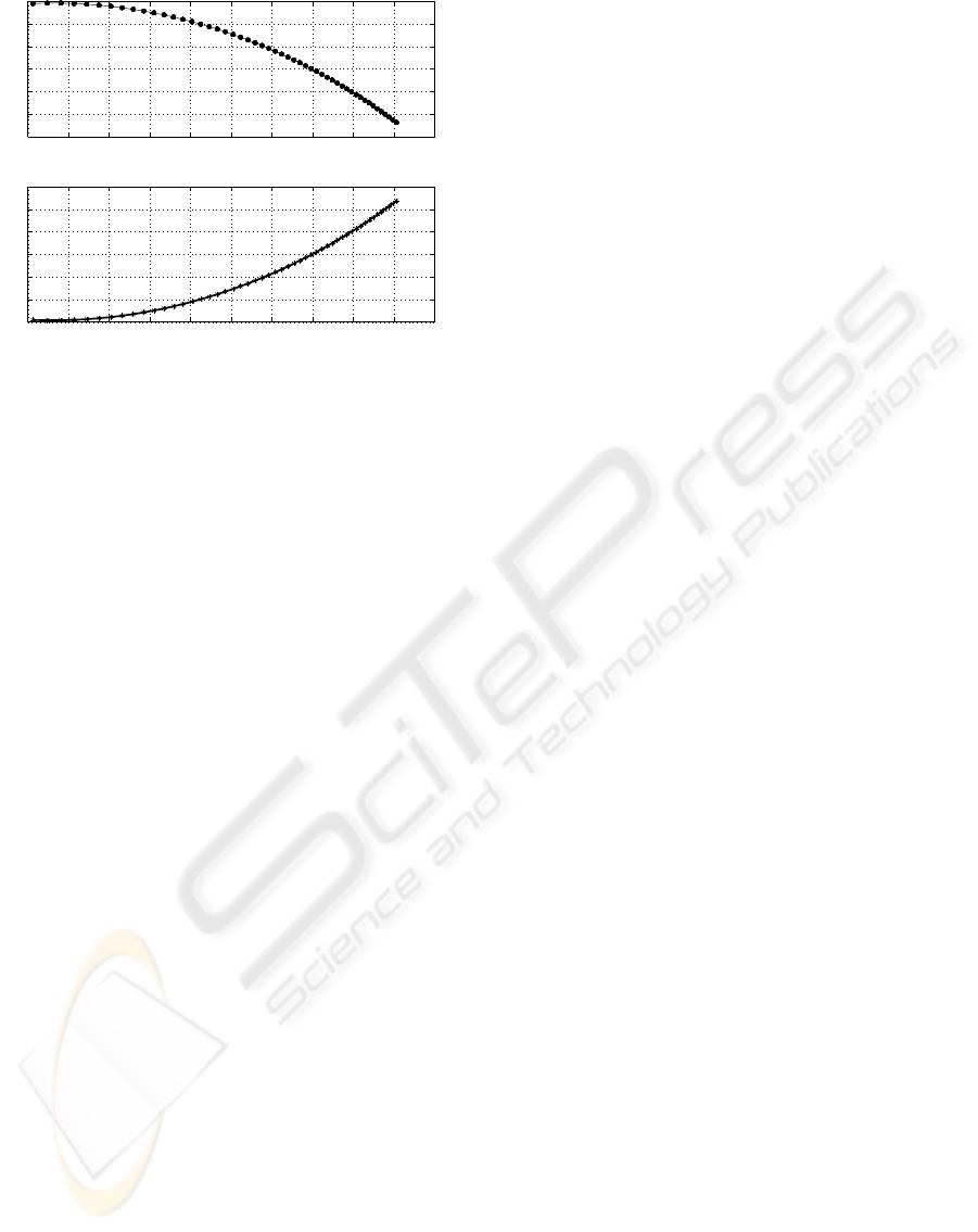
Table 1 shows the variation for the Trek 5200, the
variation in head angle and rake (which are key deter-
minants of stability) with frame size for some other
popular road bikes is shown in Fig.3.
40 45 50 55 60 65
71
71.5
72
72.5
73
73.5
74
Head angle (deg)
Klein q−pro
Trek 1000
Trek Madone
Litespeed Vortex
40 45 50 55 60 65
34
36
38
40
42
44
46
48
Frame size (cm)
Fork rake (mm)
Klein q−pro
Trek 1000
Trek Madone
Litespeed Vortex
Figure 3: Typical head angle and rake variations.
3.1 Determination of a
The horizontal position of O relative to the centre of
the back wheel, a, may be determined by a see-saw
balance to find the horizontal position of O. The set-
up is as shown in Fig.4. The bicycle, including rider,
is moved back and forth in tiny increments until bal-
ance is achieved. This arrangement was also used to
test the effect of an incline on A, with the following
ICINCO 2007 - International Conference on Informatics in Control, Automation and Robotics
240
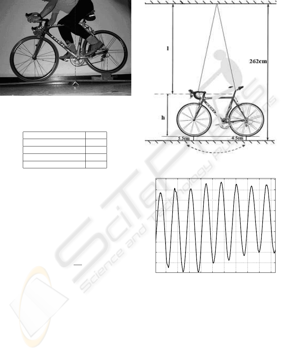
Figure 4: Experimental determination of a.
Table 2: Variation in a with incline.
Rear wheel height (m) a (m)
0 0.43
0.045 0.46
0.09 0.499
0.09
∗
0.501
results: The ‘
∗
’ denotes a condition where, with an
‘incline’ of 0.09 m, the rider leans forward to simu-
late a braking condition.
3.2 Determination of h
h can also be determined by a slightly more compli-
cated arrangement, as shown in Fig.5. The bicycle,
including rider, is induced to act as a pendulum, by
suspension of the bicycle from an overhead fixture.
For small angles of swing, the period of the pendu-
lum is:
T = 2π
p
l/g (18)
where l is the pendulum length (to the centre of
mass). The movement of the bike/rider combination
was measured by bluetooth-enabled MTx motion sen-
sor from Xsens Motion Technologies. This allows the
accurate 3 degree-of-freedom tracking of an object in
motion. Fig.6 shows a section of the output from the
sensor for the degree of freedom most closely aligned
with the pendulum motion. The average measured os-
cillation period, over three trials, is 2.622 secs. This
accords well with (average) stopwatch measurements
of zero-crossing time of 2.617. From the measure-
ments in Fig.5 and (18), we can determine h as 0.867
m. Since the mass of the bicycle + rider is dominated
by the rider (80kg Vs 9kg), one would expect O to be
roughly at the centre of mass of the rider. The mean
ratio of centre of mass to height in males has been de-
Figure 5: Experimental determination of h.
4 6 8 10 12 14 16 18 20 22
−9
−8
−7
−6
−5
−4
−3
−2
−1
Time (secs)
Displacement
Figure 6: Pendulum period determination.
termined (Elert, 2006) as 0.565, which would put h
roughly at the hip bone for the rider in question, con-
sistent with the result obtained from the experimental
determination. This provides a rough check on the
experimental result.
4 RESULTS
In this section, we examine the stability of the bicycle
model, for the parameters determined in Section 3,
BICYCLE WHEEL WOBBLE - A Case Study in Dynamics
241
with variations in frame size and aspects which might
relate to rider physique and position.
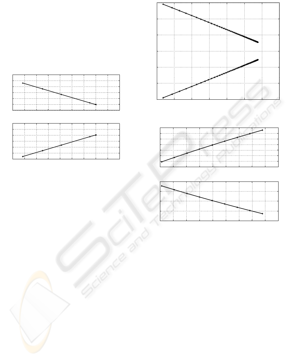
4.1 Variation in Poles with Frame Size
Using equation (14) and the data contained in Table 1,
the pole variations may be plotted for a baseline con-
dition of a = 0.43 as shown in Fig.7. It can be noted
−0.2365 −0.236 −0.2355 −0.235 −0.2345 −0.234 −0.2335 −0.233 −0.2325 −0.232
1.032
1.034
1.036
1.038
1.04
1.042
1.044
Im(s)
Re(s)
−0.2365 −0.236 −0.2355 −0.235 −0.2345 −0.234 −0.2335 −0.233 −0.2325 −0.232
−1.042
−1.04
−1.038
−1.036
−1.034
−1.032
−1.03
Re(s)
Im(s)
50 cm
62 cm
62 cm
50 cm
Figure 7: Pole variations with frame size.
that there is a perceptible movement of the poles to-
wards the imaginary axis as the frame size increases.
This suggests that, on the basis of frame geometry
alone (not taking into account frame flexibility), there
is a decrease in the stability of the bicycle with in-
creasing frame size.
4.2 Variation in Poles with Velocity
Using equation (14), for a baseline condition of a =
0.43 and a 60cm frame, the variation in the poles
with changes in velocity are computed as in Fig.8. It
is clear that bicycle stability reduces as velocity in-
creases. In the author’s experience, the onset of wheel
wobble typically occurs above 45 km/h. Note that the
condition of basic bicycle self-stabilization in (7) is
valid for the range of velocity considered in Fig.8.
4.3 Rider Position Variations
4.3.1 Horizontal Position
Again using equation (14), for a baseline condition
of V = 45km/h (equivalent to 12.5 m/s) and a 60cm
frame, the pole variations with the relative forward
position of the rider, a, can be evaluated, as shown in
Fig.9. In this case, Fig.9 suggests that, as the rider
moves more forwards on the bicycle, the stability of
the bicycle increases. This would not have been the
−0.7 −0.6 −0.5 −0.4 −0.3 −0.2 −0.1 0
−3
−2
−1
0
1
2
3
Im(s)
Re(s)
V = 16 km/h
V = 16 km/h
V = 75 km/h
V = 75 km/h
Figure 8: Pole variations with velocity.
−0.245 −0.24 −0.235 −0.23 −0.225 −0.22 −0.215 −0.21 −0.205 −0.2
0.35
0.355
0.36
0.365
0.37
0.375
0.38
0.385
Im(s)
Re(s)
−0.245 −0.24 −0.235 −0.23 −0.225 −0.22 −0.215 −0.21 −0.205 −0.2
−0.39
−0.38
−0.37
−0.36
−0.35
Re(s)
Im(s)
a=0.43 m
a=0.43 m
a=0.50 m
a=0.50 m
Figure 9: Pole variations with rider horiz. position.
impression of the author, but the result is supported
by some anecdotal evidence presented in (Limebeer
and Sharp, 2006), which documents a ‘floating sensa-
tion’ experienced by a motorcyclist on a record speed
attempt while lying horizontal on the machine. This
would, most certainly, have moved the centre of mass
of the motorbike/rider combination to the rear, with a
consequently relatively smaller value for a.
This result does not support the conclusion that the
relative increase in a, due to the rider position moving
forward under braking, causes any increased instabil-
ity.
4.3.2 Vertical Position
Again using equation (14), for a baseline condition of
V = 45km/h, a 60cm frame and a returned to its nom-
inal value of 0.43, the pole variations with the relative
vertical position of the rider, h, can be evaluated, as
shown in Fig.10. From Fig.10, it is clear that increas-
ICINCO 2007 - International Conference on Informatics in Control, Automation and Robotics
242
−0.36 −0.34 −0.32 −0.3 −0.28 −0.26 −0.24 −0.22 −0.2 −0.18 −0.16
0.36
0.37
0.38
0.39
0.4
0.41
0.42
Re(s)
Im(s)
−0.36 −0.34 −0.32 −0.3 −0.28 −0.26 −0.24 −0.22 −0.2 −0.18 −0.16
−0.42
−0.41
−0.4
−0.39
−0.38
−0.37
−0.36
Re(s)
Im(s)
h = 0.5 m
h = 0.5 m
h = 1 m
h = 1 m
Figure 10: Pole variations with rider vertical position.
ing saddle height or a more upright position of the
rider has a destabilizing effect on the bicycle, with a
migration of the poles towards the imaginary axis.
5 CONCLUSIONS
Though the simple model in Section 2 omits some
aspects of bicycle dynamics, such as frame compli-
ance, mass of front fork assembly and rider interven-
tion (via the torque input T), it can help to achieve an
understanding of the broad effects that rider position
and action has on bicycle stability. Though it is not
possible to rely on absolute pole positions returned by
the model, the relative pole movement under certain
interventions can reveal the type of actions that can
help to improve bicycle stability under certain condi-
tions.
Clearly, road (racing) bicycles attempt to achieve
a compromise between responsiveness and stability.
This is largely dictated by frame geometry and trail
(or fork rake). From the analysis in this paper, it ap-
pears that this compromise gives poorer stability for
larger framed bicycles.
The impact of rider intervention via the torque in-
put, T, deserves further examination. It is believed
(Brandt, 2005) that attempting to reduce wheel wob-
ble by rigidly holding the handlebars can, in fact,
exaggerate it, due to the spring effect of the arms.
One solution offered by an accomplished rider (who
also has considerable experience in bicycle design) is
to avoid holding the handlebars during fast descents
(Brandt, 2006). While this is likely to alleviate sta-
bility problems due to frame shortening (as a result
of braking) and exaggerated resonance via the arms,
it may have it’s own particular perils! The effect of
rider steering action could be included as a feedback
term in the model, though the parameters of such a
subsystem may not be trivial to determine.
Further work should also examine the effect of
frame compliance, since this is thought to be an im-
portant factor leading to wheel wobble and is likely to
be more pronounced in bicycles with larger frames.
However, some effects which result from component
compliance can be examined within the current model
structure. In particular, braking (with most of the
braking effect coming from the front wheel) is likely
to lead to some shortening of the wheelbase, due to
flexibility in the (carbon) forks. This could cause a
reduction in both b (the wheelbase) and R (the fork
rake). The model predicts that a reduction in both
these values would have a destabilizing effect, which
could more than offset any stabilizing effect resulting
from a movement forward in the centre of mass (un-
der downhill braking), examined in Section 4.3.1.
ACKNOWLEDGEMENTS
The authors are grateful to Denis Buckley, John Mal-
oco and Dr. Tom
´
as Ward of the Dept. of Electronic
Eng. ay NUI Maynooth for their contribution to the
experimental measurements of Section 3.1 and 3.2.
REFERENCES
Astrom, K., Klein, R., and Lennartsson, A. (2005). Bicycle
dynamics and control - adapted bicycles for education
and research. IEEE Control Systems Mag., 25:26–47.
Beghi, A. and Frezza, R. (2006). Advances in motorcy-
cle design and control. IEEE Control Systems Mag.,
26:32–33.
Brandt, J. (2005). Shimmy or speed wobble.
http://www.sheldonbrown.com/brandt/shimmy.html.
Brandt, J. (2006). Speed wobble. Private correspondence.
Elert, G. (2006). Centre of mass of a
human. In The Physics Factbook.
http://hypertextbook.com/facts/2006/centerofmass.shtml.
Hauser, J. and Saccon, A. (2006). Motorcycle modelling for
high-performance manouvering. IEEE Control Sys-
tems Mag., 26:89–105.
Klein, R. (1989). Using bicycles to teach system dynamics.
IEEE Control Systems Mag., 9:4.
Limebeer, D. and Sharp, R. (2006). Bicycles, motorcycles
and models - single track vehicle modelling and con-
trol. IEEE Control Systems Mag., 26:34–61.
Rankine, W. (1869). On the dynamical properties of the
motion of velocipedes. Engineer, 28:79–175.
BICYCLE WHEEL WOBBLE - A Case Study in Dynamics
243
