
DISTRIBUTED CONTROL ARCHITECTURE FOR AUTOMATED
NANOHANDLING
Christian Stolle
Division of Microrobotics and Control Engineering, University of Oldenburg, 26111 Oldenburg, Germany
Keywords: Automation, nanohandling, robot control.
Abstract: New distributed control architecture for micro- and nanohandling cells is presented. As a modular system it
is designed to handle micro- and nanorobotic automation tasks at semi- up to full automation level. The
architecture includes different visual sensors as there are scanning electron microscopes (SEM) and CCD
cameras for position tracking as well as non-optical force, temperature, etc. sensors for environmental
control. It allows usage of multiple nanorobots in parallel for combined autonomous fabrication tasks. The
system provides a unified framework for mobile platforms and linear actors.
1 INTRODUCTION
Handling of micro- and nanoscaled objects is an
important research field in micro system technology
(MST) and nanotechnology. While most MST
techniques are concerned with bottom-up batch
procedures for massive parallel production of micro
systems (Menz, et al., 2001) micro- and nano-
robotics tackles the nanoassebly task top-down by
applying adapted macro scale manufacturing and
control methods (Fatikow and Rembold, 1997).
This paper introduces general purpose control
architecture for automated robot-based handling.
1.1 Microrobot Automation
Automation in microrobotics encounters many of the
problems, which have been well studied in the do-
mains of industrial robotics and autonomous service
robotics for decades. Some of the problems are e.g.
collision avoidance in path planning, error handling
due to uncertainty of operations (Bennewitz and
Burgard, 2000), or timing constraints which need to
be met for successful automation.
However, there are some environmental
challenges while operating in the vacuum chamber
of an SEM. It takes several minutes to generate a
high vacuum (10
-3
- 10
-7
hPa) which is a serious time
constraint. Therefore, all cell parts of a
nanofabrication unit need to be inside of the SEM
before operation starts, including tools and objects to
be handled.
All tools, sensors and objects have to be vacuum
compliant. Depending on the kind of manipulation,
the materials need to be selected such that no conta-
mination of the workpieces can occur. E.g. actors
need to have low or even no abrasion.
For real-time position tracking of nanoobjects
like carbon nanotubes (CNTs, typical diameter about
0.4 – 100 nm) only SEM images are available due to
their high scanning rate and resolution. High
scanning rates are crucial for image acquisition in
closed-loop control, but they can only be archived
with the tradeoff of noisy image data. All this makes
real-time SEM tracking a challenging two
dimensional problem (Sievers and Fatikow, 2005).
Another challenge is that there is only limited
depth information available due to SEM by now. As
a result approaching and depth alignment of objects
and tools need to done in a try an error manner.
Automation chain planning also needs to take the
different environment and object scale into account.
In contrast to large scale objects it is harder to
release an object than to grip it. The reason for this
“sticky finger” effect (Fearing 1995) is that adhesive
forces are stronger at the scale of the gripper jaws
and samples than gravity. Therefore pick and place
operations need to be carefully planned.
One possible solution to overcome this problem
is to use electron beam induced deposition (EBiD).
One end of the gripped CNT gets fixated to the
specimen holder by the deposited material of the
127
Stolle C. (2007).
DISTRIBUTED CONTROL ARCHITECTURE FOR AUTOMATED NANOHANDLING.
In Proceedings of the Fourth International Conference on Informatics in Control, Automation and Robotics, pages 127-132
DOI: 10.5220/0001642301270132
Copyright
c
SciTePress
EBiD process just before releasing it from the
gripper (Wich, et al., 2006).
2 CONTROL OF MICROROBOTS
Several microrobots have been developed for coarse
and fine positioning to carry tools and objects. The
major categories are mobile platforms and fixed
platforms. Mobile robots are more flexible than
fixed ones due to their working range, but they are
harder to control (Ritter, et al., 1992; Hülsen and
Fatikow, 2005). Linear actors are most often
combined to a Cartesian microrobot for (x,y,z)-
coarse positioning and additional fine positioning
axes.
The control system of the nanohandling cell in
the SEM is split into two parts: high-level control
and low-level control. Low-level control
continuously compares set-point and actual value
and calculates parameters for actor steering signals.
Low-level controllers are therefore responsible for
the control of states and can process tasks as “grip
object” or “move actor from point A to point B”.
Two types of controllers are used: open- and
closed-loop controllers. Closed-loop controllers have
continuous feedback of the current system state
through sensor data while open-loop controllers just
execute a command due to their internal knowledge
of the current state.
High-level control is responsible for planning
and execution of automation tasks and for
supporting user input for tele-operation. Error
handling of low-level tasks, parallelization of
automation tasks and path planning are also part of
high-level control.
The user interacts with the control system via a
graphical user interface (GUI), which is displaying
the current system state and is forwarding user input
to high-level control.
Several different sensors measure continuously
data within the vacuum chamber (e.g. cameras,
pressure sensors, etc.). These measurements are
collected and provided to low- and high-level
control. Low-level control directly derives set values
(e.g. actuation signals) from the sensor data, which
are applied to the actuators. The update rate of the
sensor data has direct influence on positioning speed
and accuracy of the robot. High-level control sets
configuration values to sensors and actor signal
generators according to the task that needs to be
performed. It also provides input for low-level
control as position data values which are used as
goal positions for low-level closed-loop control (Fig.
1).
The reliability of closed-loop low-level control
nowadays has increased up to a level where single
tasks can be done semi-automatically, and even full
automation of various handling steps can be taken
into account. The latter is a hierarchical process
which takes place at the high-level control layer,
where the sensors for tracking can be selected, and
the sequence of process primitives is controlled.
Execution and reliability of single process primitives
is the responsibility of the low-level control layer
(Fatikow, et al., 2006).
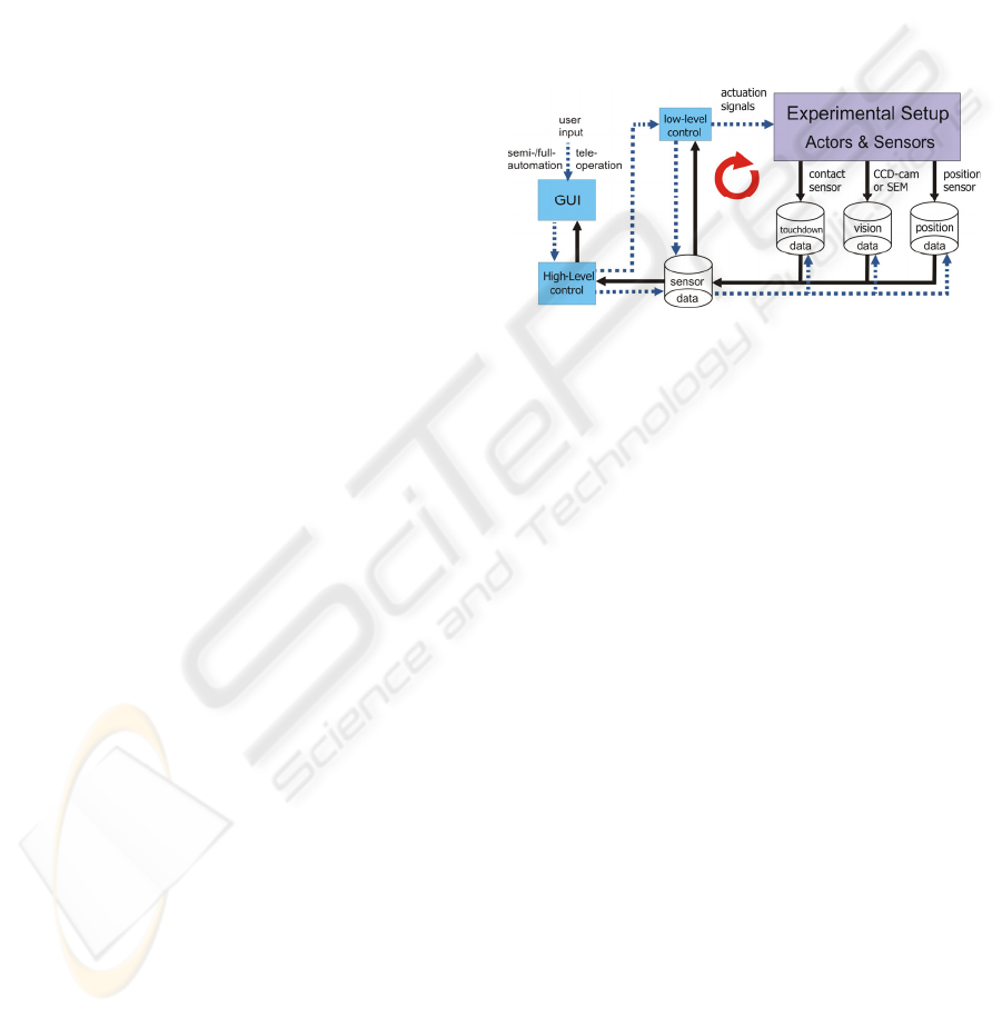
Figure 1: Control dataflow with different sensors for
continuous feedback of the current system state. Actuation
signals are generated by low-level control from sensor
input, high-level control processes user input and sends
steering signals to all components.
3 CONTROL ARCHITECTURE
3.1 Control Architecture Requirements
The rough dataflow schema for experimental setups
in figure 1 needs to be met by any control
architecture. All the actuators and sensors of the cell
need to be included into a modular control system
for successful automation. In order to be
independent of a particular experimental setup this
control system architecture needs to fulfill certain
requirements:
New actors can be integrated with low effort,
independent of the low-level control algorithm
of the actor.
New sensors can be integrated with low effort,
without the need of restructuring other parts of
the architecture.
Sensors and actors can be accessed through a
common interface to prevent changes in high-
level control.
ICINCO 2007 - International Conference on Informatics in Control, Automation and Robotics
128
The time from data acquisition till actuation
needs to be sufficiently low to be able to
archive the required low-level control results.
Communication between units needs to be
done asynchronous in order not to block parts
of the systems while waiting for others.
All commands issued by high-level control
have to be executed providing feedback about
the operation result for reliable error handling.
The architecture is able to be scaled up, such
that enough actors and sensors can be
integrated for any automation sequence.
The architecture has to allow parallel
execution of several automation tasks.
Depending on the process’ power
requirements parts of the architecture may be
distributed throughout several PCs.
This set of requirements leads to a distributed
system on a common client server basis, described
below.
3.2 Distributed Control Architecture
The system architecture applied consists of high-
level control, sensor, vision and several low-level
control server (Fig. 2) following a “Black Box
Design” (Fatikow, et al. 2006). Every server offers
an individual service which is defined by a public
interface. Therefore every component in this
modular control system can be easily replaced or
updated independently of the other components.
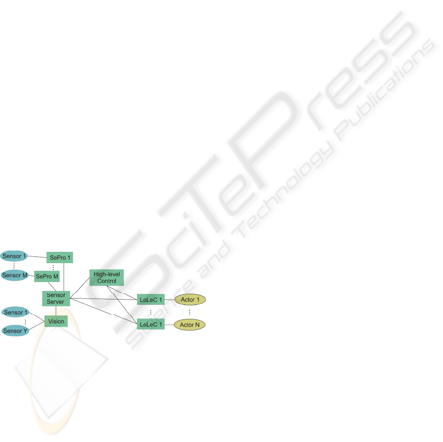
Figure 2: Software architecture connection chart.
Rectangles are servers (e.g. sensor programs SePro, low-
level controller LoLeC, etc.) and circles are hardware
components. Automation module is part of the high-level
control server.
Visual feedback is provided by the vision server. It
is responsible for collecting images from different
sources and extracts position and orientation data
(poses) of tracked objects in real-time. These poses
are transmitted to the sensor server. All sensor data
(e.g. pose, touchdown, force, temperature, etc.) are
collected by the sensor server which is supplied by
different sensor service programs (e.g. vision
server). This data is provided to low- or high-level
control, which act as client of the sensor server. It
represents therefore an abstraction layer for sensors
and builds a common interface for further process-
ing. The different sensors may acquire their data at
different update rates.
In contrast to the previous architecture (Fatikow,
et al. 2006) the newly developed one has one low-
level control server for every single actor. Each of
the low-level control server requests the data needed
for closed-loop control from the sensor server. There
is a uniform interface for commands from high-level
control. The advantage of this lean low-level control
server approach is that single servers can be easily
distributed among several PCs.
Their good maintainability is another important
feature. Furthermore, it is easy to include different –
e.g. fixed and mobile – robot platforms, because
only the internal structure of the low-level controller
has to be changed.
On the high-level control level still only poses
have to be submitted through the command
interface. Actors with internal sensors are included
into this architecture in a way that the low-level
control server provides the internal sensor readings
to the sensor server and receives high-level
commands.
In order not to adapt the high-level control server
to every change in an automation sequence, a script
language has been developed, which is described in
more detail in section 4.2. These scripts get inter-
preted by the high-level control server and then
mapped to low-level control tasks and steering
signals (Fig. 1). Low-level control tasks can either
be closed-loop for positioning or open-loop (e.g.
gripping objects) tasks. The latter have to be
monitored to check the operation results.
The proposed system architecture uses the
Common Object Request Broker Architecture
(CORBA) as communication framework, which is
an object oriented middleware defined by the Object
Management Group (OMG), and which is platform-
and language-independent. There are several
implementations of the CORBA standard, including
some for real-time applications.
CORBA’s Interface Definition Language (IDL)
is used as common language for all communication
interfaces between different network components.
Therefore the servers and clients in the system
architecture only need to implement the required
IDL interfaces to be able to communicate to each
other via simple method calls.
A major advantage of IDLs is that they can be
translated into different programming languages,
DISTRIBUTED CONTROL ARCHITECTURE FOR AUTOMATED NANOHANDLING
129
which enables heterogeneous software design. The
communication overhead in a closed loop cycle has
been evaluated to be sufficient low (< 5 µs) in a
local full switched Ethernet network. Therefore the
limiting time factor still remains to be the image
acquisition time.
The interfaces of the client server architecture
are designed to provide asynchronous
communication. All control commands return
unique process IDs so that delayed control feedback
can be matched with the corresponding command.
This part of the control feedback is crucial for
successful, reliable automation. The automation
scheduler will wait at synchronization points for this
feedback (Section 4.1). To avoid dead-locks a time-
out is issued after a sufficient time. The system has
also a common time base enabling low-level control
servers to decide whether sensor data is outdated or
not. The clock synchronization is periodically
triggered by a master clock.
Every network component is designed in a way
that it can be run on different PCs, which makes the
system fairly flexible. The distribution of low-level
control servers is especially useful for control cycles
that run in parallel because the distributed
controllers do not compete for the same PC
hardware resources. The control architecture may
contain several sensor servers for different data, to
overcome possible data acquisition bottle necks. It is
possible to organize the sensor data traffic shaping a
minimum update interval so that the inbound traffic
of any single sensor server can be controlled.
The problem of keeping several low-level control
programs maintainable is tackled by common low-
level server templates which are available for
different actor types. This also enables rapid design
and integration of new actors. Similar templates will
also be provided to sensor data acquisition server.
4 HIGH-LEVEL CONTROL
The purpose of high-level control is to processes an
automation sequence or to receive tele-operation
commands from a user via graphical user interface
(GUI). Input information is translated into low-level
command tokens called tasks and steering signals for
the selection of certain sensors.
4.1 High-Level Control Design
Based on the description above the high-level
controller provides tele-operation, automation, path
planning, error handling and parallel execution of
tasks. These different tasks are addressed in different
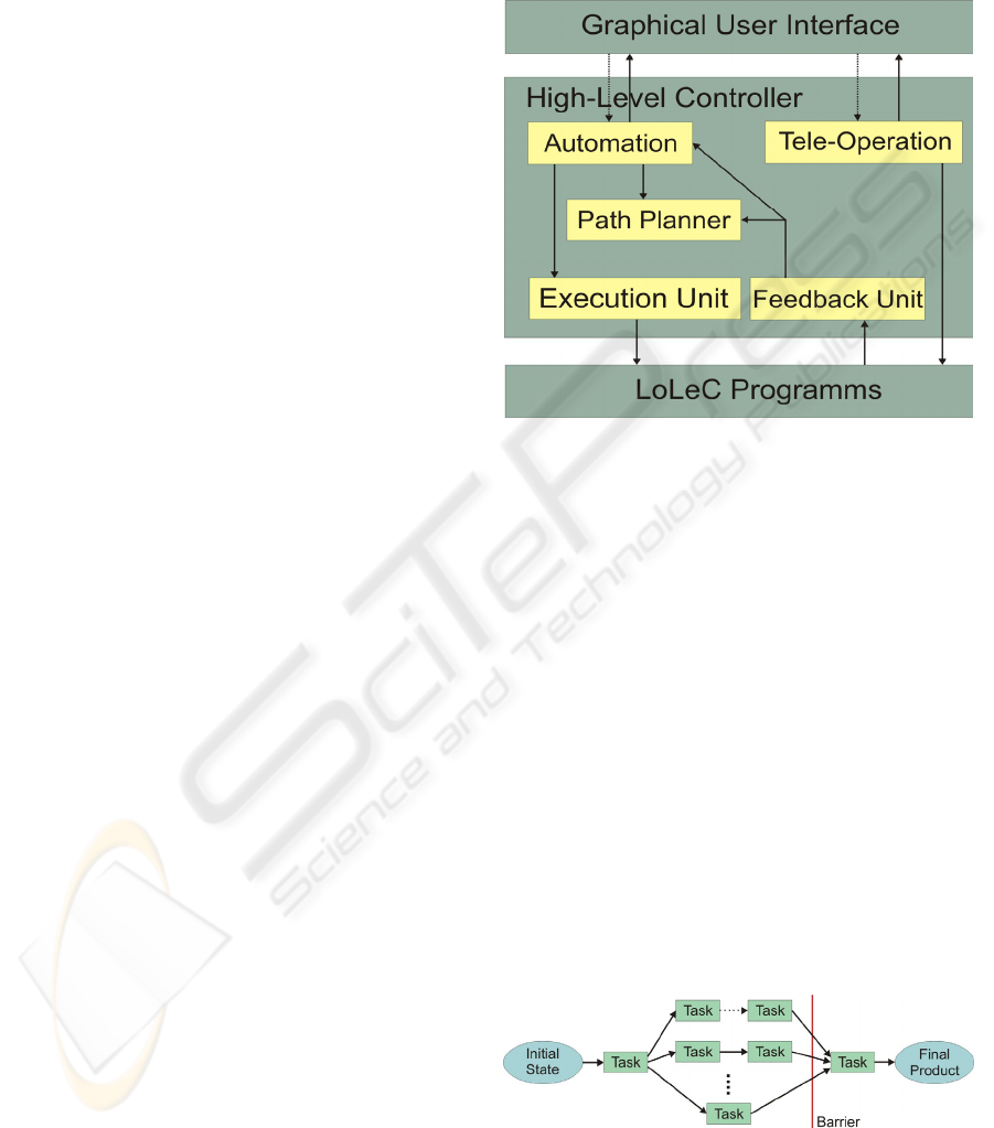
units in our high-level control design (Fig. 3).
Main trigger for high-level control is a human
controller, who inputs a tele-operation, semi- or full-
automation command using the GUI.
Figure 3: Components of a high-level controller.
If an automation command is received by the
automation units of the high-level controller e.g.
start or stop automation, a preloaded automation
sequence is processed. The sequence of automation
tasks is executed one by one or in parallel.
Every task has a defined set of pre- and post-
conditions (Section 4.2). The automation unit
decides based on required resources (e.g. sensors
and actors) and pre- and postconditions, whether two
consecutive tasks can run in parallel. These
postconditions should not be contradictive. If
resource conflicts arise, a barrier approach is taken
so that all parallel tasks are finished before
automation of the resource critical task starts (Fig.
4).
For SEM automation these resource-critical tasks
are often tasks which use the SEM as tracking sensor
for two objects on different heights or if the SEM
acts as sensor and actor at the same time (e.g. EBiD
and a concurrent positioning task).
Figure 4: Schematic view on an arbitrary automation task.
Parallel tasks are finished before resource critical tasks get
started.
ICINCO 2007 - International Conference on Informatics in Control, Automation and Robotics
130

At the automation unit level only goal positions are
visible. The main task of the path planning unit is to
break down goal positions into a discrete set of
intermediate positions that approximate the
trajectory of the robots. This trajectory should be
time efficient since bad trajectories may lead to poor
automation cycle times (e.g. rotating to the left
might be slower that moving in x, y direction.).
Another goal of path planning is to avoid collisions
with objects or other robots. For collision avoidance
an environmental model is required. Path planning
can be performed during the automation sequence
design phase or online.
On the current development state of the system
only offline path planning is supported, which is
sufficient in most cases but delegates more
responsibility to the designer of the automation
sequence.
Subgoal positions calculated by the planning unit
are sent to the execution unit as well as steering
commands of the automation unit. The execution
unit is responsible for execution of single actuation
commands.
First for every command received, all necessary
steering signals are sent to the involved programs.
These steering signals prepare all components in the
system for the low-level control command that
follows. For example the right camera is selected or
actor subcomponents are turned on or off.
After receiving an acknowledgment for every the
steering signal the low-level control command is
issued to the corresponding LoLeC.
One of the major problems in micro- and
nanorobotic is the high error rate of single
automation tasks. Due to environmental and scale
effects operations that are simple in macro
automation as positioning do have a high error rate.
E.g. there might well be endless positioning tries
because of a too low low-level control error
threshold, which was correct at a different humidity
or temperature level.
∏
∈
−−=
taskst
tseq
)1(1
εε
(1)
As in macro automation the error of a sequence is
the multiplied error rate of every single automation
task (Eq. 1). E.g. for a sequence consisting of 7 task
each having an complimentary error rate of 10% the
error rate of the automation sequence is higher then
50%.
The first step to deal with these high error rates is
a reliable error detection which is the task of the
feedback unit in the high-level controller. This unit
receives all error conditions which occurred in the
components of the system (e.g. a LoLeC) and
presents them to the right abstraction level.
Another yet not implemented task for the
feedback unit would be the observation of certain
environmental states. E.g. a carbon nanotube (CNT)
escaping from a gripper needs to be detected through
visual feedback since there is no other sensorial
information for this event. To cover this kind of
errors the feedback unit could track the CNT
through a vision sensor and rise an error condition if
the CNT gets lost.
Error conditions get handled by different units in
a different manner. If a collision is detected the
planning unit might generate a new trajectory.
On automation unit level the error handling is
performed by sweeping backwards in the automation
sequence and looking for the first task with pre-
conditions that meet the current system status.
If there is no possible way of handling an error
automatically the automation sequence is interrupted
and needs to be handled by a human controller.
The lowest level of automation i.e. tele-operation
is provided by the tele-operation unit, which directly
receives commands from a human controller. These
commands are directly provided to the
corresponding LoLeC servers. It is in the
responsibility of the human controller to avoid
collisions and move the robots to certain positions
using “save” trajectories.
4.2 Script Language for Automation
Sequences
Modeling a suitable automation sequence for a given
handling task can be performed in three steps. First,
the hardware setup has to be defined according to
the requirement analysis. Then robot-based process
primitives and their pre- and post-conditions have to
be defined (e.g. move robot to target position if it is
in range of the vision sensor). Finally, an automation
sequence is to be found, which meets all pre- and
post-conditions of the process primitives, avoids
collisions and eventually accomplishes the auto-
mation task. Additional constraints as e.g. executing
time can be taken into account as well.
The differences in process primitives between
different nanohandling robot cells (hardware setups)
impose the problems of how to avoid
reimplementation and hard coding of process
primitives and how to change the automation
sequence without changing the program code.
A flexible script language has been developed,
following the script based approach of Thompson
and Fearing (2001). The different commands of the
DISTRIBUTED CONTROL ARCHITECTURE FOR AUTOMATED NANOHANDLING
131

language are the process primitives itself. They are
implemented as sub-classes of a common task base
class. This avoids reimplementation of common
concepts as error handling or message protocols.
Composition and iteration are provided as
general language constructs. Positions as e.g.
parking or working positions for different actors can
be defined as constants and later on be used in all
commands.
Based on this script language arbitrary
automation sequences on the predefined operators
can be defined as plain text files (Fig. 5).
These sequence files gets interpreted and
executed by the high-level controller automation
unit. This way the automation sequences can take
advantage of the underlying closed-loop control. The
concept enables rapid development of different
automation sequences for the same set of process
primitives, while the high-level control program
keeps unchanged.
Figure 5: Automation sequence that lifts the specimen
holder, moves the robot into the focus of the electron
beam an grips an object.
The language design has been chosen with regard to
future application of a planning algorithm like
Metric-FF (Hoffmann, 2003) to find the optimal
automation sequence for given automation task.
5 CONCLUSIONS AND
FUTUREWORK
This paper has presented a new distributed system
architecture for controlling micro- and nanorobotic
cells competitive to the system of Fatikow et al.
(2006). However it scales up easier due to the lean
low-level control design.
In contrast to the micro handing setup in
Thompson and Fearing (2005) this system
architecture is designed for micro- and nanohandling
and full automation inside and outside a SEM
chamber.
Aside of all positive design aspects the full
capabilities of the system needs to be evaluated
carefully and applied to different kind of nano-
handling cells. So far only partial tests of
components and component interaction have been
performed.
Nevertheless subcomponents as there are the
high-level controller automation unit, the sensorial
parts and two low-level controllers for linear actors
have shown decent control behavior.
More attention also needs to be paid to
automation tasks reliability and detection of error
conditions apart from positioning tasks as described
in 4.1.
REFERENCES
Bennewitz, M., Burgard, W., 2000. A Probabilistic
Method for Planning Collision-free Trajectories of
Multiple Mobile Robots. ECAI’00. Proc. of the
workshop Service Robotics - Applications and Safety
Issues in an Emerging Market at the 14th European
Conference on Artificial Intelligence
Fatikow, S., Rembold, U., 1997. Microsystem Technology
and Microrobotics, Springer-Verlag
Fatikow, S., Wich, T., Hülsen, H., Sievers, T., and
Jähnisch, M. 2006. Microrobot system for automatic
nanohandling inside a scanning electron microscope.
ICRA’06. Proc. of Int. Conference on Robotics and
Automation, Orlando, FL, USA
Fearing, R.S., 1995. Survey of Sticking Effects for Micro-
Parts, IROS’95. Proc. of IEEE Int. Conf. on Robotics
and Intelligent Systems, Pittsburg, USA
Hoffmann, J., 2003. The Metric-FF Planning System:
Translating ``Ignoring Delete Lists'' to Numeric State
Variables. Journal of Artificial Intelligence Research
Vol. 20, pp. 291-341
Hülsen, H., Fatikow, S., 2005. Extrapolation with a self-
organising locally interpolating map. ICINCO’05.
Proc. of Int. Conference on Informatics in Control,
Automation and Robotics, Barcelona, Spain, pp. 173-
178
Menz, W., Mohr J., Paul O., 2001. Microsystem
Technology, Wiley-VCH.
Ritter, H., Martinetz, T., Schulten, K., 1992. Neural
computation and selforganizing maps. Addison
Wesley, Reading, Mass.
Sievers, T., Fatikow, S., 2005. Visual Servoing of a
Mobile Microrobot inside a Scanning Electron
Microscope, IROS’05. Proc. of IEEE Int. Conference
of Intelligent Robots and Systems, pp. 1682-1686
Thompson, J. A., Fearing, R. S., 2001. Automating
microassembly with ortho-tweezers and force sensing.
IROS’01. Proceedings IEEE/RSJ International
Conference on Intelligent Robots and Systems), Maui,
HI, pp. 1327-1334
Wich, T., Sievers, T., and Fatikow, S., 2006, Assembly
inside a Scanning Electron Microscope using Electron
Beam induced Deposition, IROS’06. Proc. of IEEE
Int. Conference on Intelligent Robots and Systems, pp.
294-299
lift(TOUCHDOWN_DIST);
move(EC,WORKING_POS);
grip(TRUE);
lift(SECURITY_DIST);
move(DROP_POS);
ICINCO 2007 - International Conference on Informatics in Control, Automation and Robotics
132
