
STUDY OF A CONTROLED COMPLEX MECHANICAL SYSTEM
IN ANTI VIBRATORY DOMAIN
Application to a Hard Landing of an Aircraft
Cédric Lopez, François Malburet
Laboratoire des Sciences de l’Information et des Systèmes, équipe Ingéniérie Mécanique des Systèmes, ENSAM
2 cours des Arts et Métiers, 13617 Aix en Provence,France
André Barraco
Laboratoire de Mécanique des Systèmes et des Procédés, ENSAM
151 Boulevard de l’Hôpital, 75013 Paris, France
Keywords: Control, excitation, high speed shock, mechanical coupling, minimization, modeling, oscillations, PID,
sliding mode, test bench.
Abstract: This paper studies problematic of a mechanical system composed of different parts mechanically coupled
and submitted to a high speed shock.
After a shock, different parts of the system oscillate. If one of them is excited at a particular frequency, such
as its proper frequency, important oscillations appear and can lead to the deterioration of the system by
introducing important stresses. In this paper, we propose an analysis in order to understand this kind of
problem and what we can do to avoid it. Firstly we discuss problematic and we expose the studied system.
In a second time, we present model which allows us to understand the phenomenon by carrying out
numerical simulations. Then we complete a comparative analysis of different methods of control. Prospects
and problematic of real controlled device are studied. Finally experimental set up is described.
1 INTRODUCTION
The topic of this paper takes place in the problematic
of the struggle against vibrations. More particularly
in the minimisation of induced vibrations by a high
speed shock in a complex mechanical system.
Vibrations and their effects are very problematic
phenomenoms for all mechanical systems. Although
there are a lot of applications, the overall of anti
vibratory devices aim the increase of the service life
of machines and structures but also the increase of
the comfort of passengers in means of
transportation.
In fact several complex systems are submitted to
external and internal excitations. There are external
excitations, like earthquakes or wind for buildings
and structures for example and road disturbances
(pothole for example) for vehicles. Internal
excitations are issued from mechanical pieces in
movement or out of balance for mechanical system.
Here we study vibrations induced by external
excitation and more especially these ones induced by
shock.
Aeronautics is a domain where it is important to
study the behaviour of an excited system. In fact
progress in the domain of materials leads frames of
aircrafts to be lighter. These ones easily bend under
an excitation. During taxiing, the fuselage is
submitted to excitations which lead to
uncomfortable situation for passengers and stressful
vibrations for the frame (Kruger, 2000). Moreover
aircrafts are particularly constrained during a
landing and especially a hard landing which is
equivalent to a high speed shock. In fact because of
the mechanical coupling existing between the
fuselage and the landing gear, the frame of the
aircraft bends and important deformations, resulting
of a particular excitation of the frame, can lead to the
deterioration of the aircraft. Reinforcement of the
fuselage can be made. But this passive solution
33
Lopez C., Malburet F. and Barraco A. (2007).
STUDY OF A CONTROLED COMPLEX MECHANICAL SYSTEM IN ANTI VIBRATORY DOMAIN - Application to a Hard Landing of an Aircraft.
In Proceedings of the Fourth International Conference on Informatics in Control, Automation and Robotics, pages 33-39
DOI: 10.5220/0001619600330039
Copyright
c
SciTePress
makes the aircraft heavier.
So in order to insure comfort of passengers and
to evict vibrations in fuselage, Ghiringhelli proposes
to control the landing gears (Ghiringhelli, 2000). In
this study, he only takes into account the cabin of an
aircraft. Here we take into account the tail beam, a
particular critic component that can easily bends
under a high speed shock and whose oscillations
lead to important stress in the area of the joint
between the cabin and the tail beam. This
phenomenon is particularly enhanced on helicopter.
Thus in order to analyse problematic and to
understand the phenomenon, we study the behaviour
of a mechanical system composed of different parts
mechanically coupled and submitted to a high speed
shock.
In order to reproduce a high speed shock, we
study the free fall and the impact on the ground of
the system. The behaviour of the upper part of the
system is particularly studied because it represents
for example the tail beam of an aircraft and so we
want to understand and to avoid its oscillations.
Thus we firstly present modelization of studied
system in order to carry out numerical simulations.
Then we complete an analysis of different methods
of control. A prospect of real device is introduced.
Finally experimental set-up is exposed.
2 MODELING
2.1 Description
In a first time, in order to simplify the study only the
main movement of bounce is taken into account. The
studied system is composed of a system which is
equivalent to a quarter part of a vehicle with another
sprung mass located on the upper mass of the quarter
part of a vehicle.
The quarter part of a vehicle is composed of a
wheel, an unsprung mass (mns) and a sprung mass
(ms) linked by a suspension (cf.
Figure 1 and Figure
5). The subsystem located on the sprung mass of the
quarter part of the vehicle, is composed of a mass
(mq), a spring and a damper. Its damping rate is
about 3%, which corresponds to a structural
damping.
We have a free fall of the system; so the speed of
the shock is proportional to the height of the fall.
Here we study a shock with a speed of 3 m/s. The
height of the fall is 0.4 m. In all following
simulations, initial conditions on positions of
different masses making up the system, allow us to
adjust the speed of the shock.
Two approaches have been studied. An
analytical approach and a multi body approach have
been presented in a previous paper. Multi body
approach corresponds to a non linear model based
on experimental characterizations of some different
constitutive parts of the system such as the tire and
the hydraulic shock absorber. After study, the non
linear model can be linearized. In this paper, we only
present and study the linear analytical model.
Moreover this one has been cross checked with
experimental tests made on the drop test bench,
described in the following of this paper.
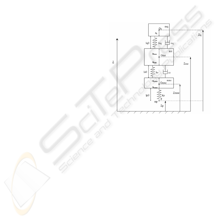
The studied system is also described by the
following figure:
Figure 1: Model and definition of parameters.
We consider four degrees of freedom (d.o.f),
which are:
-Zq, absolute displacement of the centre of mass mq.
-Zms, absolute displacement of the centre of mass
ms.
-Zmns, absolute displacement of the centre of mass
mns.
-Zp, absolute displacement of the point P.
REMARK. setting conditions on the absolute
displacement of the point P, which corresponds to
the bottom point of the tire, allow us to differentiate
the phase of fall and the phase of contact with the
ground during simulations.
In fact we have following conditions:
Zp>0, phase of fall.
Zp≤0, phase of evolution of the system on ground.
Notations:
-mq, mass of the upper system.
-Gq, centre of mass mq.
ICINCO 2007 - International Conference on Informatics in Control, Automation and Robotics
34
-ms, sprung mass.
-Gms, centre of mass ms.
-mns, unsprung mass.
-Gmns, centre of mass mns.
-kq, stiffness of the upper system.
-lq0, length of the unloaded spring kq.
-cq, damping coefficient of the upper system.
-cs, damping coefficient of the suspension.
-ks, stiffness of the suspension.
-ls0, length of the unloaded spring ks.
-kp, stiffness of the tire.
-lp0, length of the unloaded tire.
-P, point of contact of the tire.
-a
i
, distance between a centre of mass and the point
of application of a spring. The index i corresponds to
the different notations used in Figure 1.
The behaviour of the system is described by the
following equations:
()
()
()
qhms
mq Zq mq g kq Zq Zms cq Zq Zms
kq a a lq0
⋅=−⋅−⋅ − −⋅ −
−⋅−− −
(1)
(
)
(
)
()
()
()
()
qhms
bms hmns
ms Zms ms g kq Zq Zms cq Zq Zms
kq a a lq0 ks Zms Zmns
ks a a ls0 cs Zms Zmns
⋅=−⋅+⋅− +⋅−
+⋅−− − −⋅ −
−⋅− − − −⋅ −
(2)
(
)
()
()
()
mns Zmns mns g ks a a ls0
bms hmns
ks Zms Zmns cs Zms Zmns
kp Zmns Zp a lp0
bmns
⋅=−⋅+⋅−− −
+⋅ − +⋅ −
−⋅ − − −
(3)
()( )
0lpakpZpZmnskpgmppZmp
bmns
−−⋅+−⋅+⋅−=⋅
(4)
The mass mp is set to zero. When Zp>0, the
system is falling, the tire represented by the spring
with stiffness kp doesn’t apply any force on the mass
mns.
2.2 Simulations and Analysis
We study vibrations induced by a high speed shock.
In this study, free fall of system is considered. Thus
the speed of the shock is determined by the height of
the fall ie initial positions of different masses. Here
we analyse a shock with a speed of 3 m/s (a 0.4 m
high fall). Moreover we set the following condition;
no bounce of the system can occur. This is a
condition of stability for an aircraft during landing
or a condition of safety for a car riding on a chaotic
road.
The upper system is composed of the mass mq,
the spring kq and the damper cq. It has a low proper
frequency about 7 Hz.
The damping coefficient (cs) of the suspension is
different between the phase of compression and the
phase of extension. This difference makes the
suspension softer and guaranties no bounce.
After several simulations, we chose a damping
rate of 60% for compression and 90% for extension.
The damping rate, noted λ, is calculated as
following:
msks2
cs
⋅⋅
=λ
(5)
The stiffness of the spring kp modelling the tire
is set to 250000 N/m. This is an average value of the
used tire on the test bench.
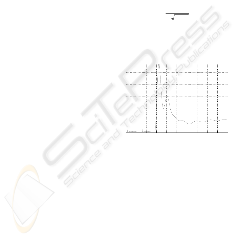
We study the excitation force transmitted to the
sprung mass (ms). We obtain the following result of
simulation:
0 0.1 0.2 0.3 0.4 0.5 0.6 0.7 0.8 0.9 1
−2000
0
2000
4000
6000
8000
Time [sec]
Force [N]
Figure 2: Excitation force on ms.
The impact occurs at the time 0.28 sec (outlined
on the graph by the red vertical dashed lined). As
soon as the impact occurs, we notice the presence of
a double bump. The first peak depends on
characteristics of the suspension (stiffness, damping
rate). The second peak depends on the stiffness of
the tire. The stiffer these elements are, the higher the
peaks are. The duration of the double bump is equal
to 0.13 sec.
Because the coupling between the mass ms and
the mass mq, the double bump excites the upper
system in a frequency band near its proper
frequency; leading to important displacements of the
mass mq.
We can conclude that the duration and the
particular shape of the excitation transmitted by the
suspension and resulting of the high speed shock are
responsible for important displacements of the mass
mq.
STUDY OF A CONTROLED COMPLEX MECHANICAL SYSTEM IN ANTI VIBRATORY DOMAIN - Application to
a Hard Landing of an Aircraft
35

Thus in order to prevent important oscillations of
the upper system, we have to control the transmitted
excitation. This one is transmitted by the suspension.
To control the dynamic behaviour of the suspension
allows us to minimize oscillations of the mass mq
and also to minimize the force on the upper system.
In the following, different methods of control of
the dynamic behaviour are designed and a
comparative analysis is presented. Then problematic
and prospects of real device are exposed.
3 CONTROLED SYSTEM
3.1 Problematic
The previous work shows that the particular
excitation transmitted by the suspension to the mass
ms, leads to important oscillations of the mass mq.
Several studies propose different controled
suspensions in order to minimize the acceleration of
the mass ms (Giua et al., 2004; Guglielmino and
Edge, 2004; Kim et al., 2003). The aim of all these
studies is to minimize the acceleration of the mass
ms in order to insure the comfort of passengers
(Yagiz, 2004). Our aim is to minimize acceleration
of the mass mq. In fact, according to the coupling
between the sprung mass (ms) and the upper mass
(mq), we will control the transmitted force on ms in
order to minimize acceleration of the upper mass
(mq).
In fact we can’t add a control force on the upper
system; that would mean a collocated actuator on the
tail beam on a real aircraft. This is more difficult and
less practicable than control the landing gear.
3.2 Comparative Analysis of Different
Methods of Control
Here we compare different methods of control. First
we study two classical methods of PID with
feedback on ms measure of acceleration and then on
mq measure of acceleration in order to respectively
minimize acceleration on ms and on mq.
Then we design sliding mode controller with
state feedback on ms using the existing coupling
between the sprung mass (ms) and the upper mass
(mq) in order to minimize the acceleration of mq.
We want to control the excitation force
transmitted by the suspension to the sprung mass
(ms). We introduce a control force, noted u, in the
equations defining the system. This force is added
on the sprung mass in parallel with passive force of
damping and stiffness. According to equations (2)
and (3) previously exposed we obtain:
()
(
)
()
()
()
()
q
hms
bms hmns
ms Zms ms g kq Zq Zms cq Zq Zms
kq a a lq0 ks Zms Zmns
ks a a ls0 cs Zms Zmns
u
⋅=−⋅+⋅− +⋅−
+⋅−− − −⋅ −
−⋅− − − −⋅ −
+
(6)
(
)
()
()
()
bms hmns
bmns
mns Zmns mns g ks a a ls0
ks Zms Zmns cs Zms Zmns
kp Zmns Zp a lp0 u
⋅=−⋅+⋅−−−
+⋅ − +⋅ −
−⋅ − − − −
(7)
3.2.1 Design of PID Controller
Considering the Laplace domain, the transfer
function used for the PID controller is the following:
d
p
id
Tp
U(p) 1
H(p) K 1
(p) T p a T p 1
⎛⎞
⋅
==⋅++
⎜⎟
ε
⋅⋅⋅+
⎝⎠
(8)
Where K
p
, T
d
, T
i
and a are tuning parameters
determined from simulations. ε(p) is the offset
between the set point and the measure of the
considered parameter.
We study two approaches. First, we minimize the
acceleration of the sprung mass (ms). On a second
time, we minimize the acceleration of the upper
mass (mq). In fact, we firstly minimize the
acceleration of the sprung mass (ms) because
according to mechanical coupling between the two
masses, we want to analyse the behaviour of the
upper mass (mq) using a PID controller in order to
minimize the acceleration of the sprung mass (ms).
Then we use the same PID controller with
minimization of the upper mass (mq), always
exerting the control force u on the sprung mass.
Results of the simulations of these two controled
systems are presented and discussed in the following
of this paper (cf. part 3.2.3).
3.2.2 Design of Sliding Mode Controller
Always using the mechanical coupling between the
sprung mass (ms) and the upper mass (mq), we
control the behaviour of the sprung mass (ms) using
a sliding mode controller in order to minimize the
acceleration of the upper mass (mq).
In this part we develop the design of the sliding
mode controller which we will implement in the
following. We have the following state vector:
ICINCO 2007 - International Conference on Informatics in Control, Automation and Robotics
36
1
2
3
4
5
6
x
Zq
x
Zms
x
Zmns
x
x
Zq
x
Zms
x
Zmns
⎡⎤
⎡⎤
⎢⎥
⎢⎥
⎢⎥
⎢⎥
⎢⎥
⎢⎥
==
⎢⎥
⎢⎥
⎢⎥
⎢⎥
⎢⎥
⎢⎥
⎢⎥
⎢⎥
⎢⎥
⎢⎥
⎣⎦
⎣⎦
(9)
In order to design the sliding mode controller, we
explain the system model as an affine system of the
form:
()
xfx gu=+⋅
(10)
Using this form, we can write:
14
44j
xx
xf(x)
=
=
(11)
25
55j 5
xx
xf(x)gu
=
=+⋅
(12)
36
66j 6
xx
xf(x)gu
=
=+⋅
(13)
Where j=1…6. Moreover we have:
()
()
21 54
4j
kq x x cq x x
1
f(x)
mq
mq g
⋅−+⋅−
=⋅
−⋅
⎛⎞
⎜⎟
⎝⎠
(14)
(
)
()
123
5j 4 5 6
kq x kq ks x ks x
1
f(x) cqx cq cs x csx
ms
ms g
⋅+−− ⋅+⋅
=⋅+⋅+−−⋅+⋅
−⋅
⎛⎞
⎜⎟
⎜⎟
⎜⎟
⎝⎠
(15)
(
)
()
23
6j
56
ks x ks kp x
1
f(x)
mns
cs x cs x mns g
⋅+−− ⋅
=⋅
+⋅ +− ⋅ − ⋅
⎛⎞
⎜⎟
⎜⎟
⎝⎠
(16)
We consider the desired state
d
2
x . The error
between the actual and the desired state can be
written as:
d
22
ex x=− (17)
Here we consider the switching surface s defined
for second order system by:
se e
=
+λ⋅
(18)
λ sets the dynamic in the sliding phase (s=0).
The control force u must be chosen so that trajectory
of the state approaches the switching surface and
then stay on it for all future time; guarantying
stability and convergence to desired state. It is
compound of a sum of two terms as following:
*
eq
uu u
=
+
(19)
The first term called equivalent control, is
defined according to parameters of the nominal
system. It is expressed as:
()
(
)
1d
eq 5 2 5 j
ug x efx
−
=⋅−λ⋅−
(20)
The second term is defined in order to tackle
uncertainties and to introduce reaching law. It is
defined by:
()
*1
5
ug ks
−
=
⋅− ⋅ (21)
The parameter k is chosen by the designer in
order to define a reaching rate.
Thus we obtain the following law of control:
(
)
1d
52
ug x eks
−
=
⋅−λ⋅−⋅
(22)
Results of the simulations of this controled
system are discussed in the following part.
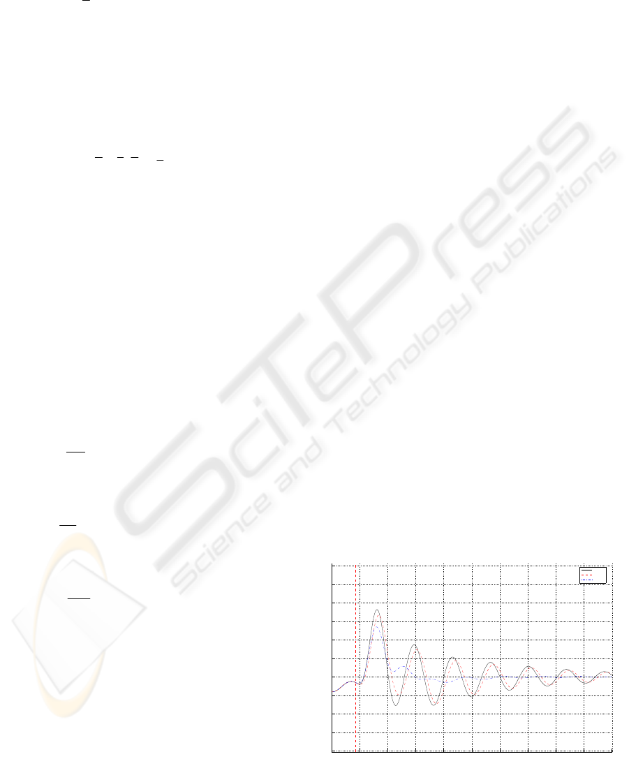
3.2.3 Analysis of Simulations Results
Simulations of the previous designed controllers
lead to following results:
0.2 0.3 0.4 0.5 0.6 0.7 0.8 0.9 1 1.1 1.
2
−8
−6
−4
−2
0
2
4
6
8
10
12
Time [sec]
Acceleration [g]
passive
PID ms
PID mq
Figure 3: Acceleration of the mass (mq) - comparison
between passive and PID controllers.
STUDY OF A CONTROLED COMPLEX MECHANICAL SYSTEM IN ANTI VIBRATORY DOMAIN - Application to
a Hard Landing of an Aircraft
37
0.2 0.3 0.4 0.5 0.6 0.7 0.8 0.9 1 1.1 1.
2
−8
−6
−4
−2
0
2
4
6
8
10
12
Time [sec]
Acceleration [g]
passive
PID mq
Sliding Mode
Figure 4: Acceleration of the mass (mq) - comparison
between passive, PID and Sliding mode controllers.
The critical point occurs at the landing during the
first compression of the landing gear. Thus, we want
to minimize the amplitude of the first peak on the
acceleration.
On Figure 3, we compare the passive system
with PID controllers minimizing the acceleration of
ms and mq (cf. part 3.2.1). The minimization of
acceleration of ms using PID is not effective on the
minimization of the acceleration of mq. Nevertheless
minimization of acceleration of mq using the same
PID is effective. In fact we have respectively a gain
of 9% and 25% in comparison with the passive
system.
On Figure 4, we compare the passive system
with PID and sliding mode controllers. Here
minimization of ms using sliding mode controller in
order to minimize the acceleration of mq is very
effective. We notice a gain of 35% in comparison
with the passive system on the first peak of
acceleration of the upper mass (mq).
Moreover in order to guaranty the stability of the
system and optimize the behaviour in minimization
of the acceleration of mq, the sliding mode
controller is operative only at the impact of the
system on the ground and during a defined time
corresponding to the proper period of the upper
system. This characteristic allows the maximum
minimization of the first peak of the acceleration of
the upper system (mq).
Thus using mechanical coupling, in order to
minimize the acceleration of the upper mass (mq),
the sliding mode controller is the most effective.
3.3 Prospects of Real Device
On the real device, we can’t add an actuator in
parallel of the passive landing gear.
In order to guaranty the maximum of stability
and to follow the control force u which will lead to
an optimal transmitted force, we keep a passive
hydraulic shock absorber that will dissipate the
majority of the shock energy and in parallel of the
passive shock absorber we add a controled throttling
device that will dissipate the rest of the energy.
This device is a semi active device where only
the damping coefficient of suspension will be
modified. Such a device doesn’t need a lot of energy
and moreover in case of failure of the controller, the
stability of the system is insured.
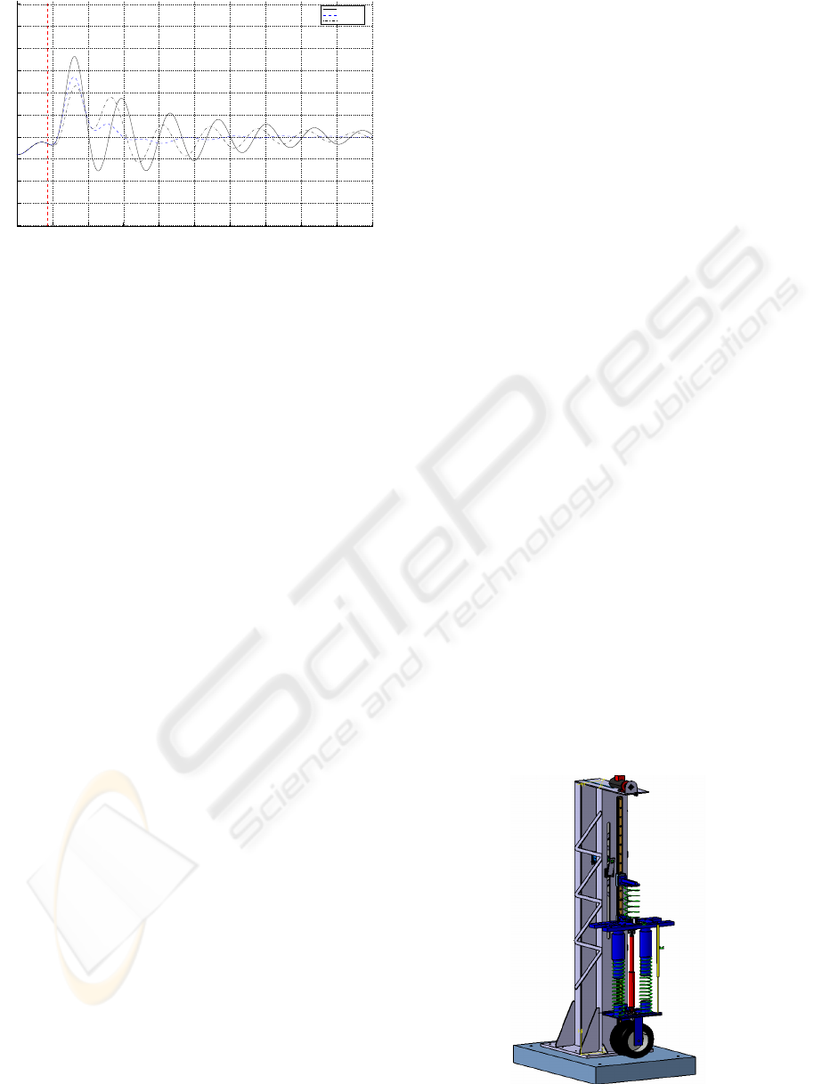
4 EXPERIMENTAL SET UP
We build a drop test bench in order to test free falls
of the system. The drop test bench is composed of a
static part and a mobile part. Two columns and a
base make up the static part. The mobile part is
composed of the quarter part of a vehicle (wheel,
suspension, sprung mass (ms) and unsprung mass
(mns)) and the upper system (mass mq, springs).
The stiffness of the suspension is insured by two
parallel linear springs. Damping is insured by a
hydraulic shock absorber. Four tuning parameters on
it, allow us to modify its characteristic damping
curve, in order to differentiate the damping rate in
domains of low and high speeds for phases of
compression and extension.
The used wheel is a wheel of an industrial
vehicle. This one has been selected because its
capacity to support heavy loads. A ball-bearing
runner insures the guide of the mobile and leads the
shock to be purely vertical.
Here frequential similitudes between a real
aircraft and each subsystem of the drop test bench
have been made. Drop test bench is represented on
the following figure:
Figure 5: Numerical mock-up of drop test bench.
ICINCO 2007 - International Conference on Informatics in Control, Automation and Robotics
38

Accelerometers on each mass insure the
knowledge of accelerations. Speeds and
displacements are determined by numerical
integrations. A force transducer between the shock
absorber and the sprung mass (ms) measures the
force transmitted by the damper. A linear inductive
displacement transducer gives the stroke of the
suspension. Thus redundancy of data on stroke of
the suspension is insured.
Several tests in different configurations have
been realized and have allowed us to cross check the
previous exposed model. Cross checking leads us to
have an accurate numerical model that allows us to
develop the controled device. In following of the
study, this one will be test on the drop test bench.
5 CONCLUSION
In this paper, a study of the induced vibrations by a
high speed shock on a complex mechanical system
has been presented. Different anti vibratory methods
of control have been designed from a cross checked
numerical model which has been previously
exposed. Cross checking results from an
experimental study that has been realized on a drop
test bench. Using mechanical coupling, a sliding
mode controller has proved its efficacy in order to
minimize the acceleration of an upper system
located on an equivalent quarter part of vehicle
system submitted to high speed shock.
Nevertheless this control force must be reachable
by a dynamical tuning of the damping coefficient of
the hydraulic shock absorber.
Thus in prospect, a semi active device has been
designed and will have to be tested.
REFERENCES
Ghiringhelli, G.L. 2000. ‘’Testing of semi active landing
gear control for a general aviation aircraft’’.
Journal of
aircraft vol. 37, No 4
. (July-August).
Giua, A.; M. Melas and C. Seatzu. 2004. ‘’Design of a
control law for a semi active suspension system using
a solenoid valve damper’’.
Proceeding 2004 IEEE
Conference on Control Applications
, Taipei, Taiwan.
(Sept.).
Guglielmino, E. and K.A. Edge. 2004. ‘’A controlled
friction damper for vehicle applications’’.
Control
Engineering Practice 12
, pp 431-443.
Kim, W.S.; W.S. Lee and J.H. Kim. 2003. ‘’Control of an
Active Vehicle Suspension Using Electromagnetic
Motor’’.
ICCAS2003, Gyeongju, Korea. (Oct. 22-25).
Kruger, W. 2000. ‘’
Integrated Design Process for the
Development of Semi-Active Landing Gears for
Transport Aircraft’’. Thesis Institut für Flugmechanik
und Flugregelung der Universität Stuttgart. 122p.
Yagiz, N. 2004. ‘’Comparison and Evaluation of Different
Control Strategies on a Full Vehicle Model with
Passenger Seat using Sliding Modes’’.
International
Journal of Vehicle Design, vol. 34, No 2
, pp 168-182.
STUDY OF A CONTROLED COMPLEX MECHANICAL SYSTEM IN ANTI VIBRATORY DOMAIN - Application to
a Hard Landing of an Aircraft
39
