
OFF-LINE SIGNATURE VERIFICATION
Comparison of Stroke Extraction Methods
Bence Kővári, Áron Horváth
Department of Automation and Applied Informatics, Budapest University of Technology and Economics
Goldman György tér 3, Budapest, Hungary
Zsolt Kertész, Csaba Illés
Department of Control Engineering and Information Technology, Budapest University of Technology and Economics
Magyar Tudósok Körútja 2, Budapest, Hungary
Keywords: Signature verification, feature extraction, stroke recovery, off-line analysis, curve fitting.
Abstract: Stroke extraction is a necessary part of the majority of semantic based off-line signature verification
systems. This paper discusses some stroke extraction variants which can be efficiently used in such
environments. First the different aspects and problems of signature verification are discussed in conjunction
with off-line analysis methods. It is shown, that on-line analysis methods perform usually better than off-
line methods because they can make use of the temporal information (and thereby get a better perception of
the semantics of the signature). To improve the accuracy of off-line signature verification methods the
extraction of semantic information is necessary. Three different approaches are introduced to reconstruct the
original strokes of a signature. One purely based on simple image processing algorithms, one with some
more intelligent processing and one with a pen model. The methods are examined and compared with regard
to their benefits and drawbacks on further signature processing.
1 INTRODUCTION
Signature recognition is probably the oldest
biometrical identification method, with a high legal
acceptance. Even if handwritten signature
verification has been extensively studied in the past
decades, and even with the best methodologies
functioning at high accuracy rates, there are a lot of
open questions. The most accurate systems almost
always take advantage of dynamic features like
acceleration, velocity and the difference between up
and down strokes. This class of solutions is called
on-line signature verification. However in the most
common real-world scenarios, this information is not
available, because it requires the observation and
recording off the signing process. This is the main
reason, why static signature analysis is still in focus
of many researchers. Off-line methods do not
require special acquisition hardware, just a pen and a
paper, they are therefore less invasive and more user
friendly. In the past decade a bunch of solutions has
been introduced, to overcome the limitations of off-
line signature verification and to compensate for the
loss of accuracy. Most of these methods have one in
common: they deliver acceptable results but they
have problems improving them.
2 RELATED WORK
The biggest limitation of off-line signature
verification methods is the absence of temporal
information. In the on-line case this can be used, to
segment the signature in a semantically meaningful
way and even to define an unambiguous matching
between the parts of two signatures. In the off-line
case no definite matching exists. These methods can
only operate on static image data; therefore they
often try to compare global features like size of the
signature or similarities of the contour (Martinez,
2004) (Miguel, 2005) (Sabourin, 1999). To get a
tractable abstraction of the two dimensional images,
these methods often involve some image
transformation, like the Hough or Radon
270
Kõvári B., Horváth Á., Kertész Z. and Illés C. (2007).
OFF-LINE SIGNATURE VERIFICATION - Comparison of Stroke Extraction Methods.
In Proceedings of the Second International Conference on Software and Data Technologies - PL/DPS/KE/WsMUSE, pages 270-276
DOI: 10.5220/0001344402700276
Copyright
c
SciTePress

transformations (Touj, 2003) or work on the density
models of the signatures (Mahmud, 2005). Although
these methods almost totally ignore the semantic
information hidden in the signature, combined with
each other they seem to give a good representation
of the signature, allowing the researchers to reach
Equal Error Rates (EER) between 10% and 15%
(Kővári, 2007). The drawback of this methodology
is that loosing the semantic information makes it
almost impossible to improve the algorithm or to
explain the results in detail. Jose L. Camino et al.
take an other approach (Camino, 1999) they try to
guess the pen movements during the signing by
starting at the left and bottom most line-end and then
following it. There are also other approaches trying
to reconstruct the signing process. In (Guo, 2000)
stroke, and sub-stroke properties are extracted and
used as a basis for the comparison. Based on own
experience, these latter approaches seem to be the
most promising, because their results can be
interpreted, explained and therefore improved.
3 STROKE EXTRACTION
By monitoring humans (including experts) during
the verification of signatures, it can be observed that
they always focus on a smaller part on both
signatures, trying to compare them. They examine
the radius of curvature, direction of strokes,
blotches, intensity of strokes, variation patterns in
the intensity etc. To make the automatic comparison
of these features possible, an almost unambiguous
matching must be defined, which is able to pair
features in two signatures, even (and especially)
when they do not look similar. The most
straightforward way to such a matching is the
reconstruction of the original signing process.
Although a perfect reconstruction is not
computationally feasible, some heuristic methods
can be defined, to get acceptable results.
Several approaches can be taken towards
restoring the strokes of the signature and each
approach has advantages and disadvantages. In the
following subsections three methods will be
introduced, which were used with success in our
verification system.
3.1 Morphological Approach
Probably the most obvious way is the morphological
image processing. Using a medial axis
transformation the skeleton of the signature can be
easily extracted, but these skeletons showed to be
highly unusable in our experiments. The most
common problems include misinterpretation of
junctions and false junctions at stroke ends.
Reducing the colour depth and converting the
pen strokes to one-pixel curves always results in an
inevitable information loss, therefore it is essential
to select a thinning algorithm which gives a good
abstraction of the original signature, with a low
noise level. We selected an algorithm, which
removes pixels so that an object without holes
shrinks to a minimally connected stroke, and an
object with holes shrinks to a connected ring
halfway between each hole and the outer boundary
(Lam, 1992), as can bee seen in figure 1.
Figure 1: Endpoint extraction on a thinned image.
This approach gives a simple representation of
the original signature. It performs good by finding
endpoints, but has difficulties with overlapping
strokes, and junctions. Although we achieved
promising results (an EER of 20%) with a simple
thinning based system (Kővári, 2007), this
representation does not fulfil the requirement of
giving a good abstraction of the original signature.
3.2 Stroke Extraction and Spline
Fitting
3.2.1 Point Extraction and Stroke
Assignment
During online signing the trajectory of the signature
can be precisely recorded by the many sensors in the
digital table that is used instead of paper. In the
following section a robust algorithm is introduced
with the purpose to identify the way how the signer
wrote his signature. The main goal was to create an
algorithm that performs well on noisy, unprocessed
images; this is why the term robust is used here. In
general, this method traces a signature using the
image of it, extracts control points from it,
determines their order, and finally assigns them to
strokes. This gives a graph representation of the
signature, which can be used for spline fitting.
OFF-LINE SIGNATURE VERIFICATION - Comparison of Stroke Extraction Methods
271
This method is a topological feature extraction
method. A topological method was introduced in
(Lee, 2005), where a general human-like signature
tracing method is described in-depth, using a thinned
signature and heuristic rules for the purpose, and
defining several solutions for removing noise caused
by the thinning process. In (Lau, 2002) a signature
thinned to one pixel width is the input for the stroke
extraction and then several cost functions are
defined for determining the overall stroke sequence.
The main goal was to improve the robustness of
these algorithms, thus the inputs were raw, scanned
images on which no noise filtering or morphological
operators (for the thinning process) were used.
(Currently morphological operators are only used for
obtaining the starting points of the signature
components, but this does not affect the original
image.)
The algorithm is based on the use of simple
virtual bows or with other word, a compass.
Beginning with a start point the pin of the bows is
stuck in it and a circle is drawn. Where this circle
sections the line of the signature, it gives an arc. The
middle point of this arc is selected as a possible
following point, and if it meets the necessary
conditions, it is taken as the new middle point.
Iteratively repeating this step the whole signature
can be traversed, but there are several difficulties to
face.
First of all the radius the bows uses has to be
determined. For this a circle is drawn with a constant
radius. If an adequately large arc is obtained, it is
stored. We start the circle with the first white point
found in order to avoid the loss of an arc, because if
we would start in the middle of the signature, we
could half an arc that is just big enough and we
would throw away its two half. After the first section
is obtained, the distance of the two edge points of
the arc is calculated, and heuristically 1.5-3 times of
its size is used as a radius. Too large values produce
too rough representation and information is lost, too
small values are simply not big enough to make a
section. To decrease the possibility of a wrongly
chosen radius size, it is further normalized in the
next few steps.
Sometimes it is not an obvious task to
differentiate between the points of the signature and
the noise. It is assumed that only blue ink is used
during the signing. With this information the blue
domination can be determined, calculated as the
difference of the blue colour component and the
average of the other two (red and green) colour
components. Splitting this parameter range in three
parts three classes of signature points can be
defined: paper, ink and undefined. In the paper and
ink classes the unambiguous points are categorized
with a heuristic threshold, the rest is put in the
undefined class.
Convexity of the points was first declared as:
two points are convexly connected, if the straight
path between them contains points only over a given
threshold. Later this did not qualify because of the
noisy input, so some undefined and even some paper
point had to be accepted.
To further improve this method, “level
difference” is calculated between the points: the size
of connected points from the same class on the path
is calculated, and where at least two continuous
points of the same kind are found, the average
intensity of the two points is calculated. This way a
quantified path is obtained, and the difference of the
highest and lowest level is calculated. This
difference is a necessary measure when too close
points must be separated, because going off the line
and coming back again can be detected this way.
Another way of path improving comes useful at
junction points. If one of the possible following
points can be reached from another one on a better
path (the maximum and total size of the undefined
and paper points is used for this parameter) than
from the junction point, then the connection of it to
the junction point is replaced with a connection to
the other point.
Loops also have to be detected and handled with
care. A loop is detected if looking ahead from the
actual point for a short distance a previously visited
point can be seen and convexly connected to the
current point. During this search the points are
prioritized in the end, junction, common point return
order (the first one found is returned).
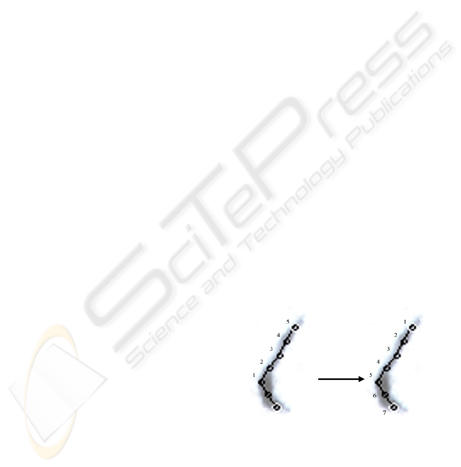
Figure 2: Point reordering at starting junction point.
To trace the signature the algorithm steps on and
over the points determined with the algorithm. If a
point has more than one possible follow-ups (this is
called junction point) then it continues in the
direction leading furthest from the previous point
and stores the other ones. If there is no acceptable
ICSOFT 2007 - International Conference on Software and Data Technologies
272

following point then the stored points are looked up,
and one of them is chosen. If there are no stored
points either, then the algorithm steps on the next
component if available. Otherwise, the algorithm is
finished. If a component starting point is also a
junction point, then the algorithm goes as far as can,
then inverts the order of the points of the stroke and
continue. This is necessary, because a starting
junction point is a fake junction.
A sample run of the algorithm is demonstrated in
figure 3. The algorithm still has some minor flaws,
but we have shown a way to extract stroke point
from noisy signatures. The order of the points should
be handled with greater care, but this tends to be an
easy task based on (Lee 2005) and (Lau, 2002).
Figure 3: Strokes of a signature: extracted points (black)
and end points of the strokes (white).
3.2.2 Spline Fitting
After the point and stroke extraction, the graph
representing the signature can be used as an input to
our decision-making system that fits splines to the
extracted points aiding the reconstructing of the
trajectories.
To compare these curves, the extracted strokes
should be approximated with an analytical form.
Polynomial interpolation is obvious to approximate
functions. However the signatures are sufficiently
varied, spiced with breakpoints and discontinues. If
a general curve is to be approximated on a large
interval, the degree of the approximating polynomial
may be unacceptably large. As an alternative
solution the full interval of signature can be
subdivided into sufficiently small intervals.
Relatively low degree polynomials on each of these
intervals can provide a good approximation to the
signature. Such piecewise polynomial functions are
called splines.
Generally, a function
s is called a spline
(Ahlberg, 1967) of degree
k on
n
xxx
<
<< L
21
if
[]
n
xxs ,
1
∈
(1)
1,,2,1,0,
)(
−= kjs
j
L are all
continuous functions on
[]
n
xx ,
1
where
)( j
s is the j
th
derivative
(2)
s is a polynomial of degree k≤ on each
interval
[
]
1
,
+ii
xx
(3)
The suitable point matching algorithm and the
consequent tracking technique guarantee the
correspondent of the splines to the same signature.
Figure 4: Original and forged signature. The differences
between curves can be extracted by applying the spline
fitting.
Using the correspondent splines, the difference
between the analytical curves can be calculated.
3.3 Pen Model
Our approach tries to capture the motion of the head
of the pen. We regard the head of the pen as a
moving object which has velocity and acceleration.
This object tries to keep these quantities at a
constant level towards minimizing the used energy,
and moving along the trace of the pen. This model
does not exactly agree with the physics of motion. If
the pen keeps its acceleration at a constant level it
does not consume energy. E.g. moving along a circle
does not use up energy, but changing the radius
does. Changing any of these quantities has almost
the same effect on the consumed energy. The cost of
changing these values is an important parameter of
the algorithm.
This model can also be considered in a different
way, which is a more visual approach. Taking a
point of the trajectory, where the foregoing
quantities are given, the aim is to calculate the new
values, which appoint the base for the next
simulation step. The velocity determines a direction,
and the acceleration determines a curvature (figure
5b). Thus a curve can be drawn from this point
approximating the unknown part of the trajectory.
OFF-LINE SIGNATURE VERIFICATION - Comparison of Stroke Extraction Methods
273
Therefore we got to a two dimensional optimization
problem. The curve, which is described by two
parameters, has to be altered in order to get the best
fitting, than the virtual object is moved one step
along this curve to get to the next simulation point.
The measure of coincidence can be derived from
the masked pixels by summarizing the intensity of
them. However this way the curve is not ensured to
be laid along the trajectory of the centre point of the
pen, but some swing around it is done (see figure
5d). To remove this unwelcome phenomenon some
image processing methods are needed. By producing
thinned versions of the track of the pen (figure 5e),
new measures can be introduced, which lead the
virtual object towards the centreline (figure 5c).
The most difficult challenge is to maximize the
fitness whilst the "energy" has to be minimized. If
the curve got too much freedom to change its
properties during one simulation step, it can easily
turn to the wrong direction at a junction (figure 5a),
or it can turn around at the end of the real curve. On
the other hand by restricting this freedom, the curve
tends to leave the centreline, stop at a hard band,
produce loops (figure 5h), or even leave the track of
the pen. There is an additional parameter which
determines the length of the test curve making the
parameter optimization more complex. A longer test
curve enables following even broken traces, but it
may also treat separate curves as one. These are the
questions when this method reaches its bounds.
Further features of the trace have to be taken into
consideration. Some information could be extracted
from the overlapping traces. Although those effect
on the image strongly depends on the type of the pen
used. In some cases nothing can be seen. By
observing the edge of the trace, useful information
can be extracted about the trajectory. As you can see
in figure 5f, it helped solving the problem which was
missed by the original algorithm. But some
preprocessing (figure 5f, figure 5g) is required with
a not trivial parameterization, making this approach
less robust.
A darker or a longer trace can divert the curve.
Like in figure 6, where the two curves run very close
to each other and the darker curve diverts the tracer.
Further development is needed to make the
algorithm keep the arc if it is possible, and alter the
curvature only if there is no choice. Our attempts to
achieve this always produced some intolerable side
effects. Probably there is no optimal
parameterization for this algorithm, thus the
parameters should be modified adaptively.
The last step of the method is still under
implementation. The virtual object has to be placed
on the trajectory and directed correctly. It is quite
simple in most cases, but when too many curves are
crossing each other, or two parallel lines are laying
close to each other it becomes a difficult task. The
letter 'a' of figure 7 depicts this challenge. The whole
trace has to be masked by the extracted curves, so
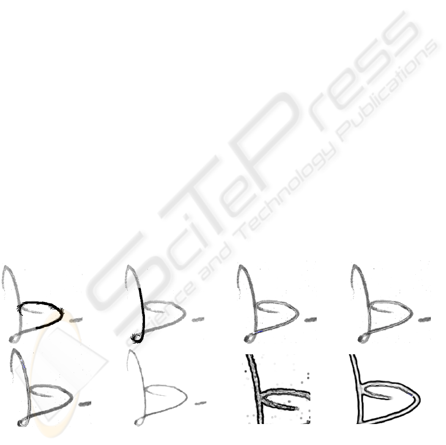
e) f) g) h)
Figure 5: a, b) The thick curve shows the estimated trajectory, the thin curves show the chosen curvature starting from each
simulation point c) the extracted trajectory d) the extracted trajectory without using thinned images e) by applying restricted
freedom for the curve, it may produce loops f) thinned image g) tracing on the edge image fails h) a median filter enhances
tracing on the edge image.
a) b) c) d)
ICSOFT 2007 - International Conference on Software and Data Technologies
274
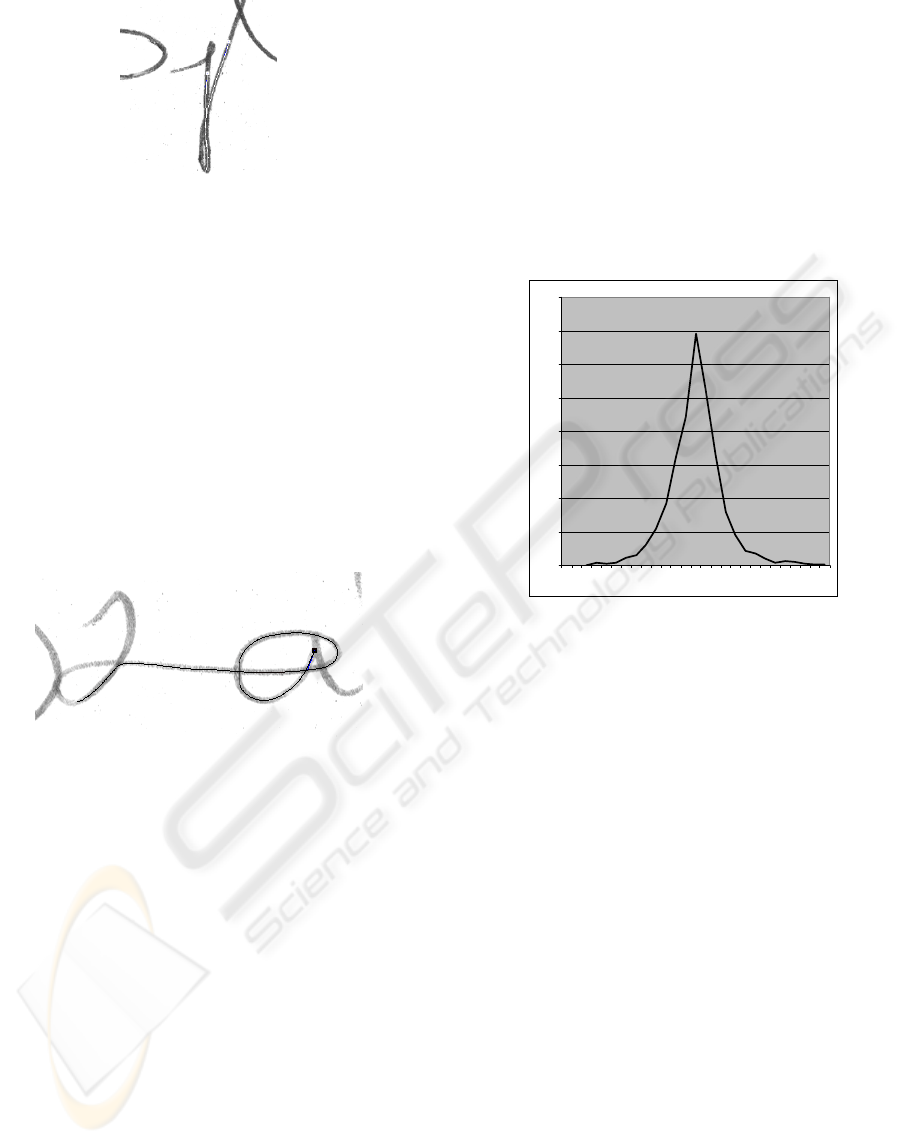
Figure 6: The algorithm fails at nearly parallel curves.
Both curve follow the better trace.
after putting some initial objects on the trajectory
randomly, the unmasked areas become the target of
the curve starter. After masking the whole trace the
curve fragments have to be joined. Then the
topology can be extracted and all the possible
trajectories can be tested, and the best can be chosen.
To reach this point the original algorithm does not
necessarily have to be improved in most cases
according to our test images, because the logic
needed to process the achieved curves has to be so
general that it must tolerate the above mistakes. But
a more reliable procedure can be achieved in
anyway.
Figure 7: Complex trajectory extracted from a sign-
manual, but a darker area diverted the curve at the end.
4 EXPERIMENTAL RESULTS
The simplest method, presented in 3.1 delivers a
brief representation of an image. The whole
signature can be characterised by 20-30 endpoints,
each having 3 parameters (vertical position,
horizontal position, direction). This allowed us to
build and test a simple signature verification system
(Kővári, 2007) based on these parameters. Although
the efficiency of this system (20% EER) is still
behind the best results of 8,9% (Armand, 2006) or
13,3% (Chen, 2005) or the 9,3% of (Srihari, 2004),
this result is still impressive, compared to the low
number of parameters used, to represent a signature.
The algorithms presented in 3.2 and in 3.3
require a more complex representation. Method 3.2
extracts in average more than 150 stroke points from
a signature, with each point having 4 parameters
(vertical position, horizontal position, next point in
the stroke, previous point in the stroke). This
information is only a partial result of the signature
verification process; therefore there are no public
researches and results to compare them with. In
order to validate the results an on-line signature
database was used (SVC, 2004). The database
already contains the original stroke information,
which could be compared with the results of the
stroke extraction algorithm (see Figure 8).
0
50
100
150
200
250
300
350
400
-13
-12
-11
-10
-9
-8
-7
-6
-5
-4
-3
-2
-1
0
1
2
3
4
5
6
7
8
9
10
11
12
13
Figure 8: The distribution of the deviance in the number of
strokes of our stroke extraction algorithm compared to the
original strokes. (Y-axis: number of signatures, X-axis:
deviance).
The method, shown in 3.3 delivers probably the
most accurate, but also the most complex
representation of the signature. Each point of the
skeleton is stored with the corresponding position,
“velocity” and “acceleration” information. This
method is still in development; thereby no
comparison to other methods can be given at the
current state of the art.
5 CONCLUSIONS
Three different stroke extraction methods were
introduced. The first one was based on simple
morphological transformations. Although this is the
simplest and fastest way of stroke extraction, the
loss of semantic information is too much even with a
carefully chosen thinning algorithm. It is not
possible to separate overlapping strokes and the
skeleton of junctions is sometimes hard to interpret.
Not so the second approach, which can be modified
to detect changes in the intensity values. It can stay
fast, because it tracks only some key points of the
OFF-LINE SIGNATURE VERIFICATION - Comparison of Stroke Extraction Methods
275

strokes, but also because of that, a further
reconstruction step is necessary involving spline
fitting. This method can give an acceptable
representation of the signature with acceptable low
computational needs (the full execution time for a
signature is under 1 second on a 2GHz processor).
Junctions are the weak point of the algorithm, which
are very hard to trace with this method. To get the
best results, the movements of the pen (and thereby,
the movements of the writer) must be taken in
consideration. The reconstruction rate is impressive.
Even complex junctions could be restored with
success, but a full processing of a signature takes
about 20 times longer, than in the previous cases.
Currently we are also experiencing some
parameterization issues, as noted in section 3.3
ACKNOWLEDGEMENTS
This project was supported by the Innovation and
Knowledge Centre of Information Technology
BME(IT
2
), the National Office for Research and
Technology (NKTH) and the Agency for Research
Fund Management and Research Exploitation
(KPI)..
REFERENCES
Martinez L.E., Travieso C.M., Alonso J.B., Ferrer M.A.,
2004 Parametrization of a Forgery handwritten
signature verification system using SVM, IEEE,vol. 2,
no. 3, pp. 193_196.
Miguel A. Ferrer, Jesu´s B. Alonso, and Carlos M.
Travieso. 2005, Offline Geometric Parameters for
Automatic Signature Verification Using Fixed-Point
Arithmetic. IEEE Transactions on Pattern Analysis and
Machine Intelligence, vol. 27, no. 6, june 2005 p 993-
997
Robert Sabourin, 1997, J.-P. Drouhard, Etienne Sum Wah:
Shape Matrices as a Mixed Shape Factor for Off-line
Signature Verification. Fourth International
Conference Document Analysis and Recognition
(ICDAR'97), pp. 661
H. A. Sofien Touj, Najoua Ben Amara, 2003, Global
feature extraction of off-line arabic handwriting, IEEE
SMC, vol. 2, no. 4.
Jalal Mahmud and Chowdhury Mofizur Rahman, 2005,
On the Power of Feature Analyzer for Signature
Verification. Proceedings of the Digital Imaging
Computing, Techniques and Applications (DICTA
2005)
Bence Kővári 2007, The Development of Off-Line
Signature Verification Methods, Comparative Study.
Proceedings of microCAD, International Scientific
Conference, 2007
Camino J.L., Travieso C.M., Morales C.R., Ferrer M.A.,
1999, Signature classification by hidden Markov
model, IEEE, no. 5.
Jinhong K. Guo, David Doermann, Azriel Rosenfeld,
2000, Off-Line Skilled Forgery Detection Using Stroke
and Sub-stroke Properties. Proceedings of the
International Conference on Pattern Recognition
(ICPR'00)
Louisa Lam, Seong-Whan Lee, Ching Y. Suen, 1992,
Thinning Methodologies-A Comprehensive Survey
IEEE Transactions on Pattern Analysis and Machine
Intelligence archive Volume 14 , Issue 9 (September
1992) Pages: 869 - 885 ISSN:0162-8828
Bence Kővári, Zsolt Kertész, Attila Major, 2007, Off-Line
Signature Verification Based on Feature Matching
INES, 11th International Conference on Intelligent
Engineering Systems, 2007 [not published yet]
Ahlberg, J. H., Nilson, E. N., Walsh, J. L., 1967, The
theory of splines and their applications. New York:
Academic Press 1967.
Sukhan Lee and Jack C. Pan (Presentted by Michael
Janssen), 2005, Offline tracing and representation of
signatures JC PAN IEEE transactions on systems,
man, and cybernetics 22:44, pp. 755-771, 2005
K K Lau, Pong C Yuen and Yuan Y Tang, 2002, Stroke
Extraction and Stroke Sequence Estimation On
Signatures. Pattern Recognition, 2002. Proceedings.
16th International Conference on pp. 119-122
Stephane Armand, Michael Blumenstein and Vallipuram
Muthukku-marasamy, 2006, Off-line Signature
Verification Based on the Modified Direc-tion
Feature. The 18th International Conference on Pattern
Recognition (ICPR'06)
Siyuan Chen and Sargur Srihari, 2005, Use of Exterior
Contours and Shape Fea-tures in Off-line Signature
Verification
. Proceedings of the 2005 Eight In-
ternational Conference on Document Analysis and
Recognition (ICDAR’05), 2005
Sargur N. Srihari, Aihua Xu and Meenakshi K. Kalera,
2004, Learning Strategies and Classification Methods
for Off-line Signature Verification. Proceed-ings of the
9th Int’l Workshop on Frontiers in Handwriting
Recognition (IWFHR-9 2004)
SVC 2004: Signature Verification Contes
http://www.cs.ust.hk/svc2004/download.html
ICSOFT 2007 - International Conference on Software and Data Technologies
276
