
COSA: AN ARCHITECTURAL DESCRIPTION META-MODEL
Sylvain Maillard, Adel Smeda and Mourad Oussalah
LINA, University of Nantes
2 Rue de la Houssinière, BP 92208
44322 Nantes Cedex 03, France
Keywords: Software Architecture, Modeling, Meta Modeling, Model Driven Engineering, Component-based Systems.
Abstract: As software systems grow, their complexity
augments dramatically. In consequence their understandability
and evolvability are becoming a difficult task. To cope with this complexity, sophisticated approaches are
needed to describe the architecture of these systems. Architectural description is much more visible as an
important and explicit analysis design activity in software development. The architecture of a software
system can be described using either an architecture description language (ADL) or an object-oriented
modeling language. In this article, we present a hybrid model, based on the two approaches, to describe the
architecture of software systems. The principal contribution of this approach is, on the one hand to extend
ADLs with object-oriented concepts and mechanisms, and on the other hand to describe connectors as
entities of first class that can treat the complex dependences among components.
1 INTRODUCTION
The increasing complexity of software systems and
their fast evolution demand models, techniques, and
methods to describe the architecture of these
systems. The designers of software systems are
confronted with several types of constraints such as
the reuse of existing code, materials and software
that can vary with time, etc. Therefore, the
description of software’s architecture requires an
organization, a capacity of control, a
communications protocol, a synchronization, an
assigned functionalities for the designed elements, a
physical distribution, and a composition of these
elements.
There are at least two different techniques to
descri
be the architecture of a software system either
by using object-oriented modeling notations
(Booch, Jacobson, & Rumbaugh, 2005) or by using
architectural description notations (or component-
based modeling, software architecture, ADLs:
Architecture Description Languages) (Medvidovic
& Taylor, 2000). Each one of these techniques
focuses on an aspect of the described system,
functional aspects for object-oriented modeling and
non-functional aspect such as security, performance,
evolution, etc. for architectural description.
The objective of our works is to develop a model
for descri
bing the architecture of software systems.
The model, which we called COSA (Component-
Object based Software Architecture), is based on
object-oriented modeling and component-based
modeling. The principal contribution of this model
is, on the one hand to extend ADLs with object-
oriented modeling concepts and mechanisms and on
the other hand to define connectors as first class
entities to treat the complex dependences among
components.
2 COSA: COMPONENT-OBJECT
BASED SOFTWARE
ARCHITECTURE
Object-oriented modeling and architectural
description have many things in common. In fact the
two have been built based on similar concepts,
which are abstraction and components interaction. In
terms of architecture in general the similarity
between the two fields is obvious. In terms of
intentions, the two fields are aimed toward reducing
costs of developing applications and increasing the
potential for related product family, hence
encouraging reusability and component based
programming. The two have their focus shifted from
lines of code to coarser grained architecture
elements and their overall interconnection structure.
Certain work showed that these two approaches
can
be used jointly for better describing the
445
Maillard S., Smeda A. and Oussalah M. (2007).
COSA: AN ARCHITECTURAL DESCRIPTION META-MODEL.
In Proceedings of the Second International Conference on Software and Data Technologies - SE, pages 445-448
DOI: 10.5220/0001338404450448
Copyright
c
SciTePress
architecture of a software system (Garlan, Cheng, &
Kompanek, 2002; Medvidovic, Rosenblum,
Redmiles, & Robbins, 2002).
COSA describes systems in terms of classes and
instances. The architectural elements
(configurations, components, connectors) are classes
that can be instantiated to define architectures. The
basic concepts of the model COSA are:
configurations, components, connectors, interfaces,
properties, and constraints. These concepts share a
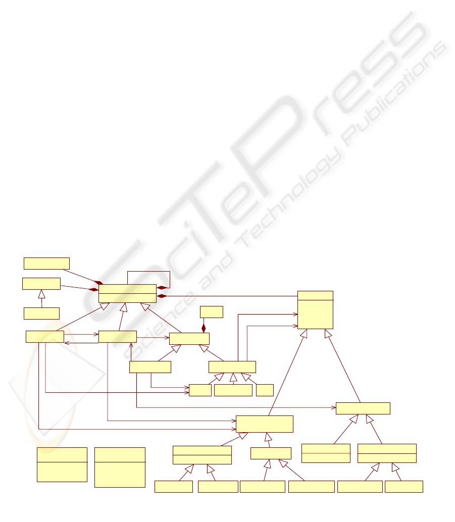
similar conceptual base. Figure 1 presents a
simplified COSA meta-model. The figure shows
among others that COSA separates the notion of
computation (components) from the notion of
interaction (connectors) and distinguishes two types
of interfaces: components’ interfaces (ports) and
connectors’ interfaces (roles). Besides, the abstract
class "Architectural-Element" gathers all the
structural and behavioral information that is shared
by components, connectors, or configurations and
therefore does not have conceptual correspondence
in traditional architectural models.
2.1 Configurations
Configurations in COSA are first-class entities. They
represent a graph of components and connectors and
describe how they are fastened to each other. A
configuration may have ports, and each port is
bound to one or more ports of the internal
components. In general, configurations may be
hierarchical: components and connectors may
represent subconfigurations that have internal
architectures.
2.2 Components
Components represent computation elements and
data storage for software systems. In COSA each
component possesses one or more ports. Ports are
the interaction points between components and their
environments.
2.3 Interfaces
Interfaces in COSA are first-class entities. They
specify connection points and provided/required
services for an architectural element (configuration,
component, or connector). Likewise, they define
how the communication between two elements can
take place.
2.4 Connectors
Connectors are very important entities that
unfortunately are not dealt with by the conventional
component-based models. In COSA, connectors are
defined explicitly and considered as first class
entities by separating their interfaces (roles) from
their services (glues) (Smeda, Oussalah, &
Khammaci, 2004).
ArchitecturalElement
+name
Interface
+name
+parent
+elements
0..1
0..*
+interfaces
+owner
0..*
Component
Connector
Configuration
UserConnector
BuiltInConnector
AttachementBinding Use
ComponentInterface
ConnectorInterface
Role
+mode: ConnectionMode
Port
+mode: ConnectionMode
Require dRoleProvidedRoleProvidedPortRequiredPort
+connectorInterfaces
0..*
+configurationInterfaces 0..*
+componentInterfaces
0..*
+connectors
0..*
+components
0..*
+detail
0..1
+detail
0..1
Property
+properties
0..*
Service
Glue
+glue
0..1
+bindings
0..*
+bindings
0..*
+source
+target
ProvidedService RequiredService
ConnectorService
+type: ServiceType
Implementation
+implementations
0..*
ConnectionMode
<<enumeration>>
+synchronous
+asynchronous
+continuous
ServiceType
<<enumeration>>
+c ommun ica tion
+conversion
+coordination
+facilitation
Constraint
Figure 1: COSA Meta-model
ICSOFT 2007 - International Conference on Software and Data Technologies
446
2.5 The Associations: Attachments,
Bindings, and Use
In addition to user defined connectors, we have built
in connectors represent different associations. In
COSA, there are three types of associations that join
the different architectural elements together:
Attachments to connect ports with roles, Bindings to
connect two interfaces of the same type (two ports or
two roles) and Use to connect services with ports or
roles. We conceder these associations are special
types of connectors, i.e. built in connectors.
2.6 Properties and constraints
Properties represent additional information (beyond
structure) about the parts of an architectural
description. There are two types of properties:
functional properties and non-functional properties.
Meanwhile, constraints are specific properties that
define certain rules and regulations that should be
met in order to ensure adherence to intended
component’s/connector’s uses.
3 DEVELOPMENT OF COSA
MODELING TOOL
This section presents the implementation of the
COSA meta-model in Eclipse.
We noted that many tools exist for this platform,
especially in the models domain. Since we want to
benefit from the tools available for this platform, we
have to consider the technological space of models
as described in (Kurtev, Bézivin, & Aksit, 2002)
instead of what we call the architectural technical
space introduced by (Smeda, Oussalah, &
Khammaci, 2005).
We focus on what tooling is needed to realize
this, after that we present an example from the tool.
Finally we end with a comparison of our work with
other existing tools.
3.1 Implementing COSA
To implement COSA meta-model, we chose eCore
(Budinsky, Steinberg, Merks, Ellersick, & Grose,
2003) as it is a Meta-Object Facility designed to be
as close to the OMG’s MOF as possible.
Our work is to provide an eCore compliant meta-
model for COSA from the initial COSA meta-model
presented in Figure 1.
The mapping activity is easily achievable since
COSA is described as a UML class diagram and
eCore is close to the UML meta-model in term of
structural description. So for COSA elements,
associations and generalization we use adapted
eCore constructs. For special cases like ‘subsets’ we
have to create customized code generation templates
to handle the subsets cases at runtime. For
constraints we used the solution given in (Damus,
2007).
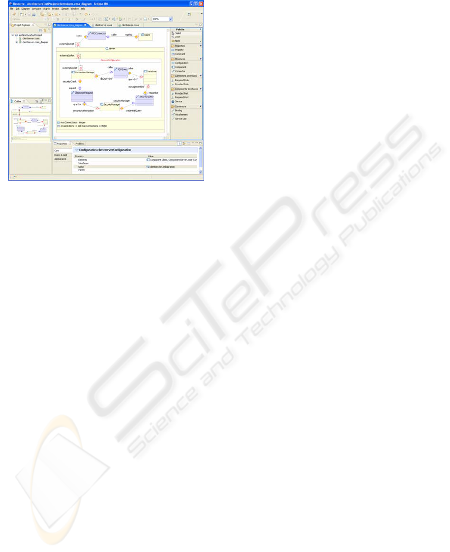
Figure 2: Client/Server Architecture using COSABuilder.
At the end of the process, we obtain an eCore
model for COSA meta-model.
With this model, we can take advantage of the
tools developed around eCore and EMF. In addition
to the tools provided by EMF, we can develop a
specific modeler for COSA using the Graphical
Editing Framework (GEF) (Moore, Dean, Gerber,
Wagenknecht, & Vanderheyden, 2004) from Eclipse
community. Developing a GEF editor requires lots
of hand coding. To avoid this, we chose to use the
Graphical Modeling Framework (GMF) (Eclipse,
2006; GMF, 2006), which is a model driven
approach to GEF application development.
3.2 Final Results
Using GMF we have implemented a full modeling
tool based on COSA definitions, we called it
COSABuilder. It is deployed as an Eclipse Plug-in.
Figure 2 shows a representation of the simple
and well known client server architecture with the
COSABuilder modeling application.
On the figure we can see some features of
COSABuilder that are inherited from Eclipse and
GMF: the Main Editor View that allows the
creation, deletion, update of COSA architectural
elements, the Project Explorer View that allows the
management of all architectures created with the
tool, the Properties View that gives access to the
COSA: AN ARCHITECTURAL DESCRIPTION META-MODEL
447

features of Architectural Elements, and the Palette
View, that contains all the tools needed by the
architect to build a COSA architecture.
3.3 Related Works
Our tool (COSABuilder) can be compared with
similar architecture modeling tools, such as
ACMEStudio for Acme
(http://www.cs.cmu.edu/~acme/AcmeStudio/index.h
tml) and ArchStudio for xADL
(http://www.isr.uci.edu/projects/archstudio/index.ht
ml). Indeed, these two applications allow graphical
representation of Architectures and interoperability
of models using standards as XML, and offer
adapted tooling, such as parser and lexical analyzer
for Acme. Comparing to these tools, COSABuilder
has a better GUI, is well interoperable, but lacks
maturity.
4 CONCLUSION AND
PERSPECTIVES
In this article we have presented a multi-paradigm
approach for software architecture based on object-
oriented modeling and architectural description
(COSA: Component-Object based Software
Architecture). It describes systems as a collection of
components that interact with each other using
connectors. In COSA, components and connectors
are defines in configurations, which describes the
topology of the system. We have also showed how
this model can be implemented as a plug-in for
Eclipse. For this, we have created an eCore meta-
model from the original UML COSA meta-model.
This meta-model allows us to model any architecture
that conforms to COSA language specification. It
opens the door to other tools that can take advantage
of architectural models in order to conduct
architectural analysis, transformations, etc. Another
useful feature is the extensibility of this meta-model:
as eCore use the same mechanism of extension that
are used for MOF (i.e. specialization, compositions
etc), we can extend COSA meta-model to include
new features.
Our future work is headed towards two
directions: the ability to create instances of COSA
Architectures to model Applications, and the
mapping of COSA architectures and instances into
existing platforms using model-to-text (i.e. code
generation) and/or model-to-model transformations.
REFERENCES
Booch, G., Jacobson, I., & Rumbaugh, J. (2005). The
Unified Modeling Language Reference Manual,
Second Edition: Pearson Education, Inc.
Budinsky, F., Steinberg, D., Merks, E., Ellersick, R., &
Grose, T. J. (2003). Eclipse Modeling Framework (1st
ed.): Addison Wesley Professional.
Damus, C. W. (2007). Implementing Model Integrity in
EMF with MDT OCL. Eclipse.org: Eclipse.org.
Eclipse. (2006). Developer Guide to the GMF Runtime
Framework.
Garlan, D., Cheng, S.-W., & Kompanek, A. J. (2002).
Reconciling the Needs of Architectural Description
with Object-Modeling Notations. Science of Computer
Programming, Vol. 44(Elsevier Press), pp. 23-49.
GMF. (2006). Introduction to the Eclipse Graphical
Modeling Framework. In Eclipse, IBM & Borland
(Eds.). EclipseCon 2006.
Kurtev, I., Bézivin, J., & Aksit, M. (2002). Technological
Spaces: An Initial Appraisal. Paper presented at the
CoopIS, DOA'2002 Federated Conferences, Industrial
track.
Medvidovic, N., Rosenblum, D. S., Redmiles, D. F., &
Robbins, J. E. (2002). Modeling Software
Architectures in the Unified Modeling Language.
ACM Transactions on Software Engineering and
Methodology, Vol. 11(No. 1), 2-53.
Medvidovic, N., & Taylor, R. N. (2000). A Classification
and Comparison Framework for Software Architecture
Description Languages. Software Engineering, 26(1),
70-93.
Moore, B., Dean, D., Gerber, A., Wagenknecht, G., &
Vanderheyden, P. (2004). Eclipse Development using
the Graphical Editing Framework and the Eclipse
Modeling Framework.
Smeda, A., Oussalah, M., & Khammaci, T. (2004).
Improving Component-Based Software Architecture
by Separating Computations from Interactions. Paper
presented at the First International Workshop on
Coordination and Adaptation Techniques for Software
Entities (WCAT'04), Oslo, Norway.
Smeda, A., Oussalah, M., & Khammaci, T. (2005).
MADL: Meta Architecture Description Language.
Paper presented at the SERA 2005, Pleasant,
Michigan, USA.
ICSOFT 2007 - International Conference on Software and Data Technologies
448
