
The Usefulness of a Generic Process Model Structure
Alta van der Merwe
1
, Paula Kotzé
1
and Johannes Cronjé
2
1
School of Computing, University of South Africa, P O Box 392, UNISA, 0003,
South Africa
2
Department of Curriculum Studies, University of Pretoria, Pretoria, South Africa
Abstract. Defining process model structures for reuse in different activities,
such as re-engineering, may seem to be an innovative idea. There is, however, a
danger that these models are created with no proof that they are useful in prac-
tice. In this paper, we give an overview of a re-engineering procedure devel-
oped from existing re-engineering procedures combined with Goldratt’s theory
of constraints, to investigate the usefulness of process model structures in such
an activity. The usefulness is measured against an ordinal measurement de-
fined.
1 Introduction
The process model is often used as a modelling tool during the re-engineering of an
environment. The identification of process models within an enterprise is a difficult
and tedious task. A problem that often occurs is that process model structures are
identified for one specific project and not stored for future reuse. The ideal is to reuse
process model structures within the enterprise, or even between different enterprises.
Firesmith and Eykholt [3] define reuse as the ‘use of some pre-existing product (e.g.
existing requirements, design, code, etc.)’.
In the re-engineering of business application domains researchers at the Massachu-
setts Institute of Technology (MIT) grasped the value of reusability and introduced it
into the building of process repositories for the business application domain [7]. In
our research, we investigated the existence of generic process model structures within
the higher education institution (HEI) application domain. However, the identifica-
tion of such structures is not of much value if they are not useful and re-usable in
activities such as re-engineering of processes within the enterprise and alignment with
information technology (IT) applications. The purpose of this paper is to comment on
the usefulness of the generic process model structure identified for the HEI applica-
tion domain in different development stages
In section 2 background is given on the identification of the process model struc-
ture. In section 3 the re-engineering procedure developed is discussed. The focus is
on the arguments that relate to the implementation of technological solutions. This is
followed with the findings of implementing the re-engineering procedure at the Uni-
versity of South Africa (UNISA) in section 4. Section 5 concludes with some com-
ments on future research.
van der Merwe A., Kotzé P. and Cronjé J. (2006).
The Usefulness of a Generic Process Model Structure.
In Proceedings of the 4th International Workshop on Modelling, Simulation, Verification and Validation of Enterprise Information Systems, pages 86-96
DOI: 10.5220/0002473600860096
Copyright
c
SciTePress
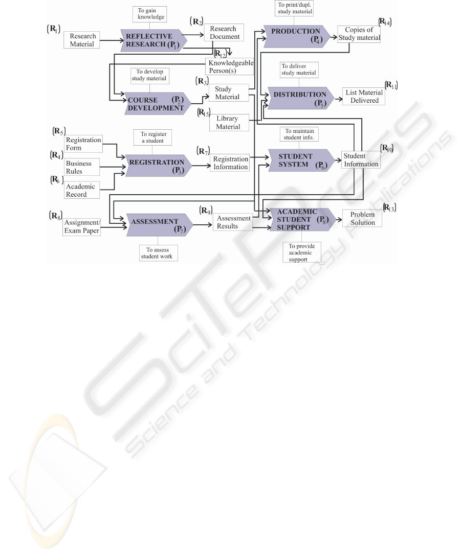
Fig. 1. Generic process model structure for HEIs.
2 Background
In earlier research we defined a requirements elicitation procedure to identify process
model structures for HEIs [13, 14]. The procedure consists of five phases. Phase 1
establishes objectives of the requirements elicitation exercise, whereas the identifica-
tion of critical enterprise units (Phase 2) and the identification of primary processes
(Phase 3) help us to understand the domain and collect stakeholder requirements. The
procedure continues with the organization of the acquired information into a high-
level process model (Phase 4), which is refined in the final step into several sub-
process models (Phase 5). This procedure was used at UNISA, the University of
Pretoria (UP) and the Tshwane University of Technology to identify a generic high-
level process model structure (Fig. 1) for HEIs. The resulting process model structure
was verified at these institutions and a fourth, the University of the Free State. Fur-
thermore, the REGISTRATION process was refined to investigate the existence of
generic process model structures on lower levels.
The identification of a generic process model structure of this nature is, however,
of no use if there is not an investigation into the usefulness of the structure. In order
to determine the usefulness of this process model structure, we defined a re-
engineering procedure and used this re-engineering procedure at UNISA (discussed
87

in sections 3 and 4). The procedure is an adaptation of existing procedures, therefore
the measurement results can be extended to similar re-engineering procedures.
We used an ordinal measurement to compare the usefulness of the process models
in the re-engineering effort, where a predefined ‘rating’ value is defined. The values
defined for measurement of the usefulness include high, medium, low and none, ac-
cording to ‘the extent’ that the process model was used in a specific phase of the re-
engineering procedure (see Table 1). If most of the phases in a procedure are meas-
ured as being high or medium, it is rated as being highly useful. If most phases are
medium or low, the procedure is rated as moderately useful. If most phases are rated
as low or none, the procedure is rated as not useful.
Table 1. Rating used to describe the ‘extent’ of usefulness for process models.
Rating Description
High A phase is rated high if the process model is used extensively and
it is not possible to commence the phase without the process mod-
els.
Medium A phase is rated medium if either the process model or the process
list is used as reference in activities in the phase.
Low A phase is rated low if there are one or two references made to the
process model.
None A phase is rated none if no reference is made to process models.
3 The Re-engineering Procedure
According to Hammer (1990), there are five steps in re-engineering when using a
process model: name the processes and state your goal; map the process; choose the
process to re-engineer; understand each process; and re-engineer the process.
This correlates with the five steps defined for process re-engineering by Davenport
and Short (1990). In both approaches the goal is to identify the processes, focus on
the process to be re-engineered and to understand the process [2, 6]. We used the
concepts from these two approaches and mapped it into a procedure to investigate the
flow within the educational application domain.
In selecting the process(es) for re-engineering in a higher education environment,
one should look at processes in which unwanted delays are experienced. The HEI
application domain is a complex environment consisting of a combination of produc-
tion and administration systems. Delays in any of these systems may cause frustra-
tions within the institution for staff or students.
The identification of constraints is an ongoing process used to improve throughput
of different components. We therefore extended the existing re-engineering proce-
dures to include constraint theory. The theory of constraints (TOC) as introduced by
Goldratt and Cox [4] was selected as the basis for identification of constraints within
the process model. A re-engineering procedure based on concepts in the theoretical
work published on Goldratt’s theory, was suggested and used on a selected process in
the higher education process model, as illustrated in Fig 2. We will discuss each of
the phases of the re-engineering procedure in more detail in the sections to follow.
88

Phase 1: Identify the
process with a
constraint
Phase 2: Identify
constraint in sub-
process
Phase 5: Imlement
changes and evaluate
results
Phase 3: Identify
reason(s) for
constraint
Phase 4: Consider
solutions for the
problem
Fig. 2. Re-engineering procedure.
3.1 Phase 1: Identify the Process Subject to a Constraint
A constraint, or bottleneck, is any resource or sub-process whose capacity is equal to
or less than the demand placed on it [9]. The first step in finding solutions for possi-
ble constraints is to identify the delays. Any process with an output created by the
process has the potential to contain constraints. The re-engineering team should first
identify the high-level processes within the HEI application domain before the proc-
ess to be re-engineered is selected (following a procedure as described in section 2).
The process model in combination with the following procedure is used to identify
the constraints:
1. Use a high-level process model to identify (or focus on) possible constraints.
2. Derive from the process model a table that lists all the processes P
k
where k = 1:m,
where m denotes the total number of processes.
3. List a throughput value and a demand value for each process. The possible values
for throughput are the set {possibility, none, satisfactory, a} and similarly for de-
mand the set {possibility, none, satisfactory, b}.
• A numeric value a and b is assigned to the attributes throughput and demand
respectively, where it is possible to determine actual numeric values.
• A value of ‘possibility’ is assigned to the attributes throughput and demand if
the re-engineering team suspects a constraint in sub-processes, but is not sure.
• A value of ‘satisfactory’ is to the attributes throughput and demand if the cur-
rent throughput or demand is satisfactory and ‘none’ if the it is not quantifi-
able.
4. Add a column indicating constraint values to the table with a value of ‘Yes’ indi-
cating a constraint or a value of ‘No’ if not. This value is determined using the
definition of a constraint with the following algorithm assigning a ‘Yes’ value to
any process in which the current throughput is less than the demand, or where the
‘possibility’ of a constraint exists:
if (throughput = ‘satisfactory’ or throughput = ‘none’) then constraint = ‘No’
else if throughput = ‘possibility’ then constraint = ‘Yes’
else if demand > throughput then constraint = ‘Yes’
else constraint = ‘No’;
89

Table 2 gives an example for process P
k
with a throughput of 100 units per hour
and a demand of 120 units per hour. Using the algorithm provided, a constraint is
identified based on the demand being more than the throughput.
Table. 2. List with processes and resources derived from process model.
Process Throughput Demand Constraint
P
k
100 120 Yes
P
k+1
None None No
Management can, depending on its priorities, select the process(es) that need(s) re-
engineering from this list. Selecting the process for re-engineering is a strategic deci-
sion and should be made by the relevant stakeholders of the enterprise after consider-
ing the resources available to investigate the constraints.
3.2 Phase 2: Identify Constraint in Sub-process
The second phase in the procedure re-engineering team is to determine the sub-
process that causes the constraint in the selected process. The selected process may
have more than one scenario that influences the throughput. For example, when re-
engineering at UNISA we found that the REGISTRATION process had two scenar-
ios: counter registrations and postal registrations (including electronic registration).
All relevant scenarios will have an influence on the final throughput and demand
values. If there is more than one scenario the development team should select one to
focus on depending on the objectives of the re-engineering effort, or repeat the activi-
ties for all the scenarios to be re-engineered.
In Phase 1 the re-engineering team used a high-level process model to assist in se-
lecting the process for re-engineering. In Phase 2 a similar procedure is necessary for
the sub-processes in the selected process. The following procedure is suggested:
1. Select the scenario with the constraint (if there is more than one scenario).
2. Determine the list of sub-processes for the process being scrutinized.
3. Determine the demand and throughput values for each sub-process.
4. Identify the constraint(s) in the list of sub-processes as in Phase 1.
5. Select the sub-process(es) to be scrutinized.
6. If the selected sub-process has sub-processes, go back to Step 2 and repeat the
procedure.
The deliverable of this procedure is a list of sub-processes for a process P
k
on the
higher-level process model, with one or more possible constraints within the list of
sub-processes. The re-engineering team then decides on the biggest constraint that
should be addressed in the remaining phases, or repeat the process for more than one.
3.3 Phase 3: Identification of Reason(s) for a Specific Constraint
The third phase is to identify the reasons for the specific constraint. The chain of
events consists of two dimensions: the chain of events of the constraint and going
deeper into underlying paradigms, policies and measures [10]. For each application
domain, the reasons for constraints may differ. In a business environment a product is
sold with financial gain from the product and demands are created by the market. In
90

a production system the development team will need to look at the different processes
from a scheduling perspective. In the educational environment the focus is not higher
production for financial gain, but on higher throughput for better service. Unfortu-
nately, there is not a repository of reasons for constraints. Van der Merwe [13, 15]
does, however, suggest a non-exhaustive list of types of reasons that the developer
might want to consider in the analysis of the constraint
The deliverable of this phase is for the development team to write a report listing
the reasons for the constraints. This is the most important step in finding the solution
to constraints in a chain of events and a great deal of interaction will be needed with
role players in that chain.
3.4 Phase 4: Consideration of Solutions to the Problem
In Phase 4 the re-engineering team should consider solutions to the constraints identi-
fied. There are two approaches that the re-engineering team can select from during re-
engineering efforts. The first is to look at the chain of events and to simplify it by
combining several activities (or eliminating some) using technological innovations.
The second is to focus only on the activity with the constraint and look at feasible
solutions for the single activity. There are various solutions that the development
team may consider in using technology for either of the approaches. The following
are guidelines for selecting a technology innovation as a solution:
• Consider different options do a feasibility study before deciding on the direction.
• Consider the use of tools to determine what the current state of technological use is
within the enterprise for the specific process.
• Acknowledge the importance of resistance to change and incorporate it in imple-
mentation strategies [1, 11].
• Consider the effect on role players and resources in implementing the changes that
will not show necessarily in using the different tools discussed.
• Decide on an implementation plan, giving direction in the search for a solution.
3.5 Phase 5: Implementation of Changes and Evaluation of Results
The last phase consists of the implementation, testing and evaluation of the solution.
Before implementation it is necessary to look at concerns that the new solution will
raise and to evaluate the changes after implementation to ensure that the constraint is
eliminated and that the solution does not create a still bigger constraint. The team may
now return to Phase 2 where the list is once more examined to identify new con-
straints that might appear after the elimination of the current one.
4 Re-usability of the Procedure – Re-engineering at UNISA
To illustrate the re-engineering procedure’s re-usability, it was used in a re-
engineering effort at UNISA. Due to space limitations it is not possible to give de-
91
tailed information on all the data gathered during the procedure, but we give a brief
discussion on the results from the re-engineering procedure.
4.1 Data-gathering at UNISA in Phase 1
The five steps defined for Phase 1 were followed. The high-level process model iden-
tified previously (Fig 1) were used and according to the throughput and demand cal-
culations, four processes were identified with possible constraints: COURSE
DEVELOPMENT, PRODUCTION, ASSESSMENT and REGISTRATION (Table
3). The REGISTRATION process was selected by the stakeholders for the remaining
steps of the re-engineering process.
Table 3. Throughput and demand on processes in the high-level process model
Proc-
ess
Process Throughput Demand Constraint
P
1
REFLECTIVE RESEARCH None None No
P
2
COURSE DEVELOPMENT Possibility Possibility Yes
P
3
REGISTRATION 71246 (1/12-
9/2)
90739 Yes
P
4
PRODUCTION Possibility Possibility Yes
P
5
DISTRIBUTION Satisfactory Satisfactory No
P
6
LEARNING ACTIVITIES Satisfactory Satisfactory No
P
7
ASSESSMENT Possibility Possibility Yes
P
8
ACADEMIC STUDENT
SUPPORT
Satisfactory Satisfactory No
4.2 Phase 2: Identify Constraints in Sub-process
From the ten sub-processes listed for REGISTRATION, the Application-Process on
the second level of decomposition and Student-Number-Application, Student-
Number-Allocation, Register-and-Verify-Student-Payment, Course-Profile-
Verification and Course-Data-Capture on the third decomposition level, were identi-
fied as possible constraint processes. The last two were selected as the sub-processes
to focus on because the biggest time delay was experienced in them (at the Under-
graduate Unit nearly 10000 student enrolments are delayed in the Course-Profile-
Verification and Course-Data-Capture sub-processes).
4.3 Phase 3: Identification of Reason(s) for a Specific Constraint
According to staff at the Undergraduate Unit, applications are in a queue (in the order
received) where a first-in-first-out rule is applied. The physical processing of one
application is more or less 10 minutes. In the interview the following were significant
reasons given for the delays: staff members are constantly busy with telephone en-
quiries on the status of student applications; student applications are duplicated for
fear that the first application has not been received; incorrect information is received
92

from student, i.e. re-registration is required; there are only a few people who can
handle the exceptions in course verification; the data on the expert systems used is
not updated by responsible role players; management does not realize how dire the
lack of resources is; counter students (65000) involved in the REGISTRATION proc-
ess get precedence over electronic / postal students and in busy registration periods
when staff members are primarily assigned to the counter registration.
It is preferable that the proposed solution should consider and address a large pro-
portion of these concerns if it is to be considered successful.
4.4 Phase 4: Consideration of Solutions to the Problem
There is more than one solution for the electronic registration system. Finding a fea-
sible solution for an electronic registration system at a university is a tedious task.
The development team may consider the use of existing software that is available or
decide to develop in-house software. The first option may seem ideal, but software
available for administrative tasks of this nature is very expensive and it is often not
possible to customize it to interact with existing systems. An alternative is to develop
the system in-house. This could also be an expensive option, but has the advantage
that the software is customized according to the existing legacy systems. A feasibility
study is necessary and because the purpose of this research was to focus how one can
manage flow in existing systems, we focused only on the options available for im-
plementing a customized electronic registration system at UNISA.
The constraint that the solution should focus on is in the Application-Process on
the second level. This sub-process is ideal for automation if there is a system that
handles the application electronically. A system of this nature will be ideal if it can be
a registration management system (RMS) that handles the application from inception
until the final registration of the student. It will therefore not only benefit the Aca-
demic-Verification sub-process, but will also focus on the other constraints in the
Application-Process, Payment-Verification and Course-Material-Distribution. This is
in accordance with the re-engineering procedure, which states that a solution can
either focus on a single constraint at a time or focus on a chain of events.
In the Application Process, we suggested the use of an RMS system similar to the
one already in use at UP. The proposed solution is graphically depicted in Figure 3.
For the Academic-Verification we suggested the use of the existing UNISA Expert
System, but recommend that it be integrated with the central management system. For
the Payment-Verification we recommended a limitation that the process only makes
provision for automatically registered payments. For the Course-Material-
Distribution we suggested the use of a system where the student gains access to his
course material as downloadable PDF material. In the centre of the suggested auto-
mated electronic system is the RMS, which is a software management system respon-
sible for managing the application from the moment that the student initiates the ap-
plication process until the course material is dispatched to the student. The activities
managed by the RMS and the advantages of its implementation is described in detail
in [15]:
93
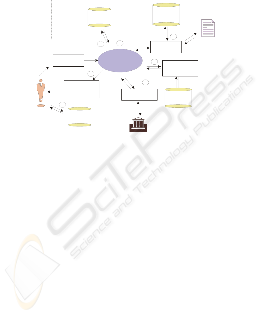
Fig. 3. The suggested Registration Management System
4.5 Phase 5: Implementation of Changes and Evaluation of Results
For feasibility purposes, a small-scale version of the registration system was imple-
mented by a project student at UNISA [5]. Full implementation requires a long-term
commitment from all stakeholders in the enterprise. The recommendations in this
research may act as starting point in development. Some of the functions are already
available independently at other institutions (such as UP) and therefore feasible for
implementation.
5 Usefulness of the Procedure
In order to discuss the usefulness we list the different phases with comments on the
usefulness of process models in each phase in Table 4. In the last column the indica-
tors mentioned in Table 1 were used to indicate to what extent the process models
were used in the specific phase. If most of the phases in a procedure are measured as
being high or moderate, it is rated as useful to a high extent, if most phases are mod-
erate or low, it is rated as useful to a moderate extent, if most phases are low or none,
it is rated as a useful to a low extent.
Re
g
istration
Management
System
Electronic
Application
Give Student
access to Course
Material
Admission
Procedure
Student Course
Profile
verification
3
4
6
5
7
8
2
Matriculation
Results
Database
Scanned
Certificat
e
Student
Database
Course
Material
Student
Student
exist?
Expert
System
Payment
Payment verification
at bank
Continuously
updating
Student
Database
Update Student
Database
94

Table. 4. Role of process models in different phases.
Phases Documentation Comments on the role of the process
models
Indication
of useful-
ness
Phase 1:
Identify
main con-
straint
High-level proc-
ess model
Process list
The high-level process model is used to
identify the process list, which is then
once again used to determine the con-
straint in each process. Without knowing
what the processes are, it is impossible
to identify the high-level constraint.
High
Phase 2:
Identify
constraint in
sub-process
Sub-process
models
Sub-process list
The sub-levels are used to identify the
process lists on each level and the con-
straint on each level. Without knowledge
of what the sub-processes are, it is im-
possible to identify the constraint on
each level.
High
Phase 3:
Identification
of reason for
constraint
Reasons for
constraints
Although the process models are not
prescribed directly as a tool in this
phase, it may be a valuable graphical
tool in discussions with role players in
the institution to investigate the reasons
for constraints.
Low
Phase 4:
Considera-
tion of solu-
tions
Solution options
Feasibility study
Process models
The process list is used to look at alter-
native chains for a constraint chain of
processes or at innovations to enhance
the sub-process scrutinized.
High
Phase 5:
Implement
changes
Adapted process
models
After implementation it is necessary to
update the existing process models for
future reference of the chain of events
depicting the flow within an institution
Medium
The process model and process lists derived from the process model are used on all
levels of the suggested re-engineering procedure. In three of the five phases a ‘High’
value is given to ‘the extent’ that the process models were used. Phase 5 received a
‘Medium’ value for use in the procedure, while only Phase 3 received a ‘Low” value.
None of the phases received a ‘None’ value. It is therefore possible to deduce that
the procedure is useful to a high extent if used in a re-engineering activity such as that
described in this Chapter. It is useful both for deriving the processes with constraints
and ideal for re-engineering and as a graphical tool in the process.
6 Summary
It is very difficult to measure the usefulness of an artefact such as a process model
structure. Process models are used in practice in re-engineering efforts as a visualiza-
tion tool [8, 12] to understand the processes and the workflow between them. To
discuss the usability and usefulness of the process model structure a re-engineering
procedure was defined for identification of problem processes within the educational
95

application domain. The procedure was used at UNISA to test its re-usability and
usefulness based on an ordinal measurement approach in which indicators are used to
show how useful the structures were in the re-engineering effort. The process models
were used extensively in the re-engineering effort and were therefore categorized as
being highly useful.
For future research we are looking into the possibilities of creating a repository
where the process models can be stored for future re-use.
References
1. Conger, J., The New Age of Persausion, in On Leading change: A leader to leader guide, F.
Hesselbein and R. Johnston, Editors. 2002, Jossey-Bass, Wiley: New York, USA. p. 19-31.
2. Davenport, T. and Short, J., The new industrial engineering: Information technology and
business redesign. Sloan Management Review, 1990. 31(4): p. 11-27.
3. Firesmith, D.G. and Eykholt, E.M., Dictionary of Object Technology; The Definite Desk
Reference. 1995, New York: Sigs Books. 603.
4. Goldratt, E. and Cox, J., The goal: A Process of Ongoing Improvement. 1992, Great Bar-
rington, MA: North River Press.
5. Green, H. and Van der Merwe, A., System Analysis: Automated Electronic Registration
System. 2004, University of South Africa: Pretoria.
6. Hammer, M., Reengineering work: Don't automate, obliterate. Harvard Business Review,
1990. 68(4): p. 104-113.
7. Malone, T.W., Croston, K., Lee, J., Pentland, B., Dellarocas, C., Wynor, G., and Quimby,
J., Tools for inventing organizations: Toward a handbook of organizational processes.
Mangement Science, 1999. 44(3): p. 425-443.
8. Malone, T.W., Crowston, K., and Herman, G.A., Organizing Business Knowledge. 2003:
MIT.
9. Onirik. What is the theory of constraints (TOC). 2000 [cited September 2004]; Available
from: http://www.onirik.com.au/Theory%20of%20Constraints%20TOC.htm.
10. Patrick, F. Using TOC to Avoid Disappointment in Improvement Programs. in 2002 Na-
tional Solutions Conference of the Institute of Industrial Engineers. 2002. Norcross, GA.
11. Senge, P., Lessons for Change Leaders, in On Leading change: A leader to leader guide, F.
Hesselbein and R. Johnston, Editors. 2002, Jossey-Bass, Wiley: New York, USA. p. 19-31.
12. Van der Aalst, W., Desel, J., and Oberwies, A., Business Process Management, Models,
Techniques, and Empirical Studies, in Business Process Management, Lecture Notes in
Computer Science Vol 1806, G. Goos, J. Hartmanis, and J.v. Leeuwen, Editors. 2000.
13. Van der Merwe, A., Kotzé, P., and Cronjé, J., The Functionality of a Requirements Elicita-
tion Procedure Developed for Process Modelling within the Higher Education Application
Domain. Alternation, 2005. 12(1b): p. 478-503.
14. Van der Merwe, A., Pretorius, L., and Cloete, E., A requirements elicitation process model-
ling technique for incorporation of e-learning as a core learning strategy. Journal of Inte-
grated Design and Process Science, 2004. 8(3): p. 1-16.
15. Van der Merwe, A.J., Towards Reusable Process Model Structures for the Higher Educa-
tion Institution, in School of Computing. 2005, University of South Africa: Pretoria. p. 352.
96
