
VALIDATION OF INFORMATION SYSTEMS USING PETRI NETS
Asghar Bokhari and Skip Poehlman
McMaster University
Hamilton, Ontario, Canada
Keywords: Dynamic analysis, Petri nets, UML state diagrams, Agents, EPSS.
Abstract: Enterprise information systems are complex software that are frequently required to adapt to rapid changes
in business environments. Although there have been some successes, the research literature is full of horror
stories due to failure of these systems. Current software engineering practice requires verification/validation
of complex systems at the design stage. Unified Modeling Language (UML), which lacks formal semantics,
is the defacto standard for designing the majority of information systems and that means dynamic analysis
techniques cannot be used for validation of UML models. Consequently there has been a considerable interest
among researchers in formalization of UML models. Early proposals translate UML state diagrams into
some kind of mathematical language and input this textual description to a model checker. In this paper we
present a rule-based technique to convert UML state diagrams to Object Coloured Petri (OCP) nets. A strong
mathematical foundation, more amenable to verification and validation procedures, along with a graphical
representation, makes Petri nets ideally suitable for dynamic analysis of UML modelled information systems.
1 INTRODUCTION
It is generally agreedthat there is a need to developin-
formation systems that are flexible and that adapt eas-
ily to the rapid, ever-changing industrial and business
environments. It should also be possible to accom-
modate new business processes without the need to
rewrite the entire information system ((Venkatraman,
1994), (Rober, 1999), (Buchsbaum et al., 2001)). In
order to meet these requirements we earlier reported
(Bokhari and Poehlman, 2004) a proposed architec-
ture for an agile Electronic Performance Support Sys-
tem (EPSS) based on service oriented architecture
(SOA) where services are implemented using soft-
ware agents. Most of the research related to analysis
and design of information systems including the agent
oriented software development is based on ”princi-
pled but informal ” methodologies (Wooldridge and
Ciancarini, 2000). They have, most of the time, used
object oriented analysis and design methodologies
based on UML and have proposed extensions or adap-
tations to make these methodologies applicable to
agent oriented development (Wooldridge et al., 1999).
However UML is based on semi-formal semantics
and does not support dynamic analysis whereas soft-
ware engineering practice requires such analysis and
validation at an early stage in the software develop-
ment process. In this paper we show how a UML
model of an agent-based information system can be
transformed to an Object Coloured Petri Net (OCPN)
model that can be used for simulation and dynamic
analysis.
2 RELATED WORK
Current research differentiates the strong notion of
agency followed by AI researchers ((Wooldridg and
Jennings, 1995), (Nawana, 1996)). We follow the
weak notion of agency and use reactive software
agents in our system, as defined in (Tosic and Agha,
2004).
Agent-based software systems are being used for
significant applications where agents must work in
cooperation with traditional software systems. There
is a major need for industrial strength approaches to
engineer agent-based systems to avoid the possibili-
ties of developinginvalidsystems (Singh, 2000). Rec-
ognizing the popularity of UML in the software in-
dustry, researchers have focussed on formalization of
UML models for dynamic analysis. Earlier attempts
concentrated on translating UML models to mathe-
matical models using formal languages like Z, HOL
and PVS (Rysavy, 2003). In (Lilius and Paltor, 1999),
the authors use vUML to translate a ”flat” represen-
tation of UML statecharts into PROMELA, which is
the input language to the model checker SPIN. This
approach however does not support dynamic creation
or deletion of objects. (Latella et al., 1999) pro-
pose a conversionof the hierarchical representation of
UML state diagrams to extendedhierarchical automa-
ton (EHA) as an intermediate step and then translate it
to PROMELA. A survey of efforts to formalise UML
can be found in (Rysavy, 2003). A common weak-
ness of all these approaches is that they fail to provide
a high level of abstraction that can be properly under-
284
Bokhari A. and Poehlman S. (2006).
VALIDATION OF INFORMATION SYSTEMS USING PETRI NETS.
In Proceedings of the Eighth International Conference on Enterprise Information Systems - ISAS, pages 284-289
DOI: 10.5220/0002447802840289
Copyright
c
SciTePress
stood and implemented by systems engineers ((Varro,
2002), (Rysavy, 2003)). Coloured Petri Nets (Jensen,
1997) are well known for their formal foundations,
their graphical appearance, their simulation and anal-
ysis capabilities and their support for modeling of
concurrent systems (Philippi, 2000). This has gener-
ated much interest in the translation of UML models
to Petri Nets. Most of these proposals suggest algo-
rithms based on a set of rules that can be followedstep
by step to translate UML models into Petri Nets.
(Wagenhals et al., 2002) report an algorithm to
facilitate the conversion of UML based Object Ori-
ented artifacts into executable CP net models. They
use class diagrams to provide the basic structure for
the conversion to a CP net. The paper does not de-
scribe how objects of different classes communicate
with each other and how an object can be created /
deleted. ((Merseguer et al., 2002), (Bernardi et al.,
2002)) present proposals for translating UML mod-
els to Generalized Stochastic Petri Nets (GSPNs) for
performance evaluation. (Zhao et al., 2004) propose
their set of rules using a series of graph transforma-
tion steps. Saldana (Saldana and Shatz, 2001) gives
algorithms for translating UML state diagrams to Ob-
ject Petri nets. We have used some of their results
in our research; however, they translate the UML di-
agrams into Object Petri Nets, which are based on a
fixed number of objects that must be determined be-
forehand. This approach presents a major hurdle in
using the technique to develop agent-based software
for complex systems where agents need to be instan-
tiated and deleted multiple times during the run time
of the system and the number of agents of a particu-
lar type should not be constrained as constant at the
design stage (Philippi, 2000).
Our technique translates a UML state diagram to
Object Colour Petri Nets (OCPNs) (Maier and Moldt,
2001) in which individual nets represent classes of
agents. Specific facilities added to class nets result
in instantiation and deletion of agents represented as
coloured tokens. Agent to agent as well as envi-
ronment to agent communication is handled through
communication channels.
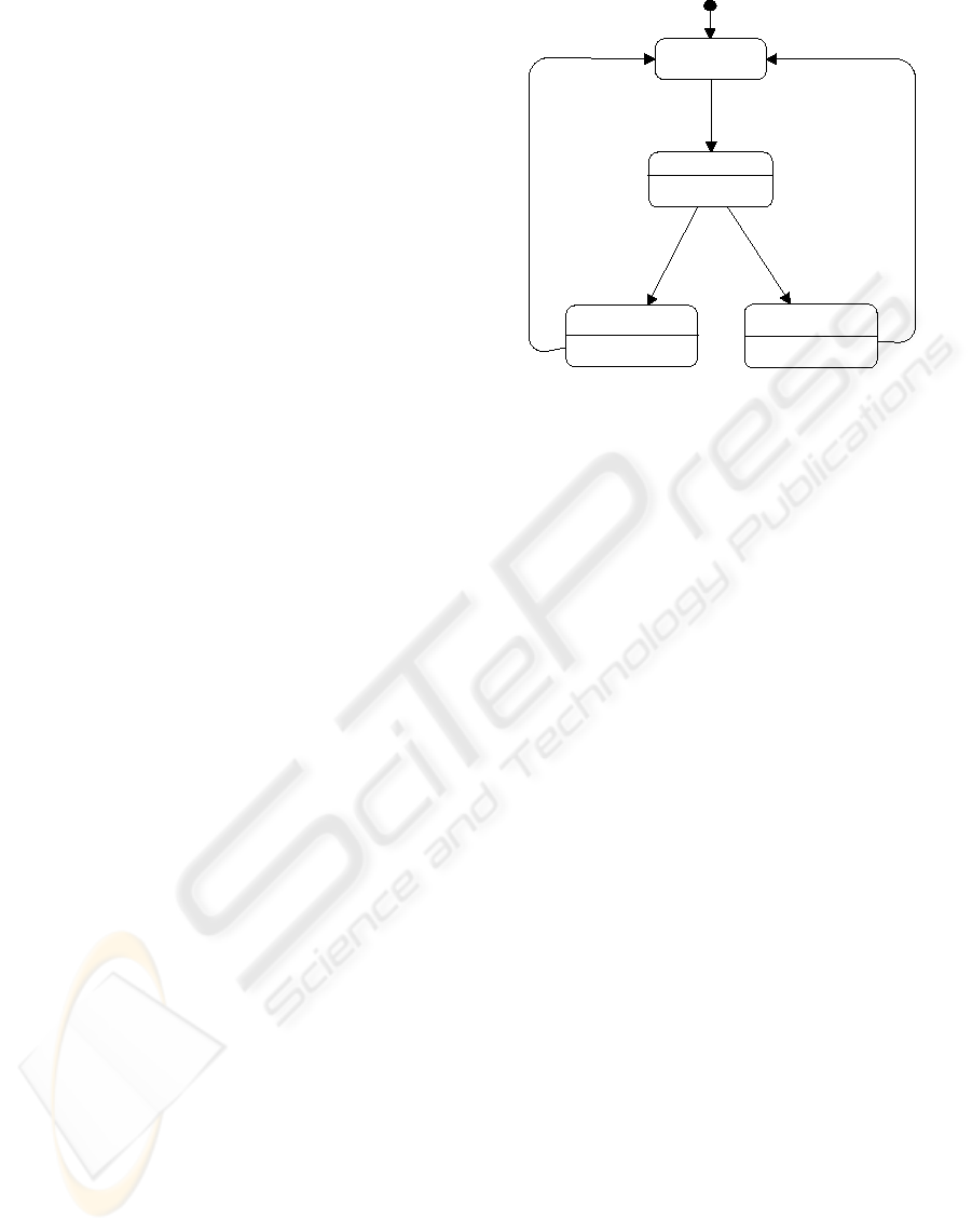
3 UML AGENT MODELING
The behaviour of an agent can be described as a se-
quence of states the agent is in, changing from one
state to another in response to external events consist-
ing of interaction with other agents or with its envi-
ronment. Each state may represent one of its activ-
ities including when it is idle waiting for something
to happen in its environment. The change of state
may be accompanied by the execution of an action
that could consist of a local action by the agent or
Idle
1
do:Filtering
2
4
3
entry:^UA.ErrorMsg
entry:^UA.Send(Inf)
AID.Get(X)
Processing
Error
Complete
Completed
Incomplete
5
Figure 1: State Diagram of Information Agent.
sending a message to another agent. By transforming
UML model of an information system to a Petri net
model, we can simulate the system and study its dy-
namic properties such as fairness, boundedness, live-
ness, deadlock-freeness and reversibility etc.. We do
this by using a higher level abstraction of each agent
in the system, similar to the concept of skeleton in
(Singh, 2000), where an abstract state may corre-
spond to a number of computation states considered
alike for dynamic analysis of the system. Based on
this abstraction, behaviour of an information process-
ing agent can be represented by the UML state dia-
gram shown in figure 1.
4 OUR APPROACH
We want to define a step-by-step method that will
transform a UML behavioral specification repre-
sented by UML state diagrams and interaction dia-
grams to an OCP-net that represents the behavioral
specifications of the system formally, so that the cur-
rently available tools for CPN may be used for the
simulation and analysis of the system. This involves
the following steps:
a. We assume that a UML model, consisting of class
and interaction diagrams, is available for an agent-
based system and UML state diagrams represent-
ing the behaviour of agents belonging to different
classes have been constructed at a level of abstrac-
tion discussed in section 3.
b. We transform the state diagram of each agent to an
OCP net by following the algorithm given in sec-
tion 5 and call it an Agent Model.
VALIDATION OF INFORMATION SYSTEMS USING PETRI NETS
285
c. Each Agent Model is converted into a Class Model
by adding necessary facilities.
d. Class nets are integrated into an OCPN represent-
ing the system, by two sets of communication chan-
nels for asynchronous messages that represent the
internal events within an agent as well as the ex-
ternal events created by other agents in the sys-
tem, indicated by interaction diagrams. Although
OCPNs provide mechanisms for both synchronous
as well as asynchronous communication, we imple-
ment only asynchronous channels because the nor-
mal mode of communication for software agents is
by asynchronous message passing.
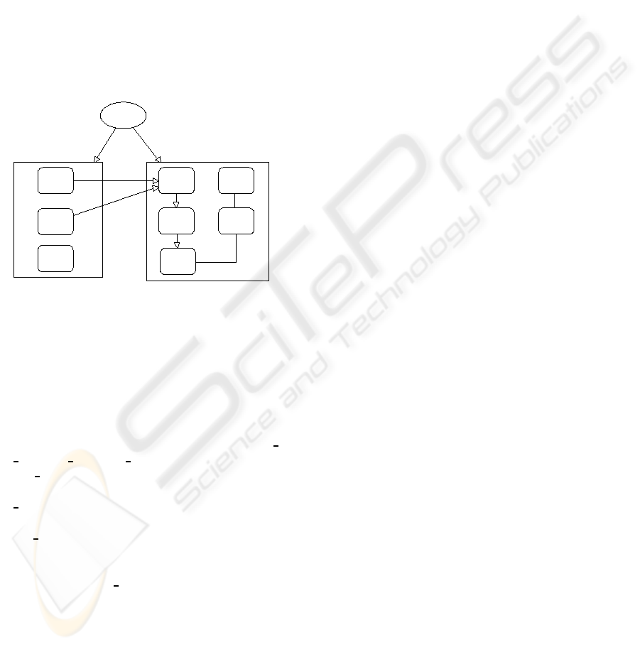
Different stages of the design and analysis phase are
shown in figure 2.
User
n
-State
D
iagrams
I
nteractio
n
Diagram
s
O
ther
U
ML
D
iagrams
n
-Agent
M
odels
n
-Class
M
odels
O
CP-net
w
ith
C
hannels
A
nalysis
S
imulatio
n
UML Editor
Design/CPN
Figure 2: Overview of the Design and Analysis Process.
4.1 From UML to OCPN
An Agent Model (AM) is a tuple <BM, MP> where
BM is a CPN that models the lifetime behavior of an
agent as specified by the correspondingUML state di-
agram and interaction diagrams with MP = { msg
in,
msg inv, msg out, msg rec } a set of four places:
(1) msg in contains all tokens representing messages
requesting some service of the current agent; (2)
msg
inv contains all tokens representing messages
sent by the current agent requesting some service;
(3) msg
out contains all tokens representing messages
sent by the current agent as an acknowledgement or a
return value for a message received earlier from an-
other agent; (4) msg
rec contains all tokens repre-
senting messages sent to the current agent by another
agent as an acknowledgement or a return value for a
message sent earlier by the current agent.
A Class Model is an enhanced version of an AM
that meets the formal definition of a class net given in
(Maier and Moldt, 2001). It is obtained from the AM
by adding: (1) Four transitions (T
in
,T
inv
,T
out
,T
rec
)
and four places (P
in
,P
inv
,P
out
,P
rec
) to handle com-
munication between agents; (2) Two transitions Cre-
ate and Delete to handle creation and deletion of to-
kens representing agents of the class; (3) A finite set
of instance fusion sets, if necessary, for the class at-
tributes.
We use the terms input place, output place, input
transition, output transition, input arc and output arc
as defined in (Jensen, 1997), i.e. a node x is called
an input node of another node y, iff there exists a di-
rected arc from x to y. Analogously, a node x is called
an output node of another node y, iff there exists a
directed arc from y to x.
The class models discussed above must be con-
nected together so that messages may be passed be-
tween different agents. This is done by creating two
channels using the concept of global fusion places. A
set of global fusion places consisting of P
in
and P
inv
places in all class models is created to act as chan-
nel 1. Channel 2 consists of global fusion places P
out
and P
rec
of all classes. Here we have used the mod-
eling guidelines proposed by (Jensen, 1997) for asyn-
chronous communication with acknowledgement.
5 ALGORITHM
Precondition: A UML state diagram is available for
each class in the UML class diagram.
Begin 1. For each state diagram
Begin Using Design/CPN
(a) Convert the state chart into an Agent Model
using Algorithm 1
(b) Transform the Agent Model to a class net us-
ing Algorithm 2
End
2. Connect the class models by a set of global fu-
sion places defined as
Channel1 =
n
i=1
P
ini
∪
n
i=1
P
invi
Channel2 =
n
i=1
P
outi
∪
n
i=1
P
reci
where n is the total number of class nets.
End
5.0.1 Algorithm 1
Begin For each state diagram
1. If there are any composite states, flatten them to
simple states
2. Examine the state diagram and assign a unique
identifier to each state transition
3. Create the following tables for all state transi-
tions:
ICEIS 2006 - INFORMATION SYSTEMS ANALYSIS AND SPECIFICATION
286

Table 1: State Diagram Table A.
Transition# Input State Output State Events Guards
Table 2: State Diagram Table B.
Transition# Input State Exit
Action(s)
Output State En-
try Action(s)
Transition
Action(s)
4. Start with a new CPN page and create four places
named msg
in, msg inv, msg out and msg rec
and position them close to the top, bottom, left
and right of the page.
5. For each state transition
(a) Create a CPN transition and transform the
guard conditions to CPN guards
(b) Create a CPN input place for the input state and
a CPN output place for the output state. If a
state already exists do not duplicate it.
(c) If there is a state transition event
then If this is a local event, create a CPN in-
put place for it
ElseIf the event is a message received from
another agent then create an input arc from
msg
in place to this transition and another
from a place containing a token of the agent
receiving the message.
ElseIf the event represents a returned value
from a previousaction then draw an input arc
from the msg
rec place and create an output
place for the value returned.
EndIf
EndIf
(d) If there is an action for the state transition or
an entry action for the output state or an exit
action for the input state
then If it is a local action, create an output
CPN place for it.
ElseIf this action is a message (M) for an-
other agent, draw an output arc to msg
inv
place from the transition. Create CPN input
places for all parameters and draw arcs from
these places to the transition. Specify initial
markings for these places to represent the pa-
rameter values.
ElseIf an action results in sending of a return
value or acknowledgement to another agent
then draw an output arc to msg
out place.
EndIf
EndIf
End
5.0.2 Algorithm 2
Begin 1. Create four CPN transitions named
T
in
,T
inv
,T
out
and T
rec
and four CPN places
named P
in
,P
inv
,P
out
and P
rec
2. Draw an input arc to T
inv
and T
out
from msg inv
and msg
out places of the Agent Model respec-
tively
3. Draw output arcs from T
inv
to P
inv
and T
out
to
P
out
4. Draw an output arc from T
in
and T
rec
to msg in
and msg
rec places of the Agent Model respec-
tively
5. Draw input arcs to T
in
from P
in
and to T
rec
from
P
rec
6. Add facilities to create and destroy agents in the
class by adding a create and a delete transition
with input arcs from the msg
in place and in case
of the create transition, an output arc to a place
(AllIDS) that contains all agent ids for the class
and in case of the delete transition an input arc
from this place.
7. Draw an input-output arc between T
in
and Al-
lIDS to ensure that a message is passed on to an
agent only if it exists.
8. A create or delete message is handled by the
class and it places a token representing the newly
created agent in the initial place of the net repre-
senting the class. In case of deletion, the token
is consumed by the transition implementing this
message.
End
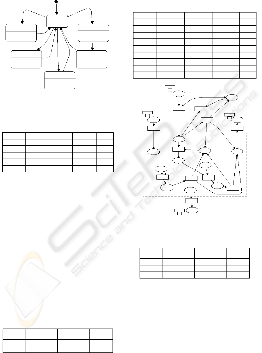
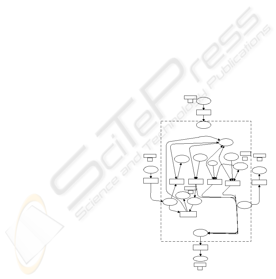
6 ILLUSTRATIVE EXAMPLE
Application of the above algorithm is now illustrated
by an example that consists of two agent classes: a
user agent class acting as the root class and an infor-
mation agent class. The UML state diagram of the in-
formationagent is shownin figure 1 and that for a user
agent is shown in figure 3. The User creates an infor-
mation agent and then requests it to provide informa-
tion based on a filter. The information agent returns
the information on completion of a search if success-
ful. In case it encounters an error, an error message is
sent to the user. Tables 3, 4, 5 and 6 collect the infor-
mation required by the algorithm from the two state
diagrams. Finally figures 4 and 5 show the OCPN
class models for the information agent class and the
user agent class respectively. The parts of these dia-
grams enclosed in a dashed box represent the corre-
sponding agent models referred to in the algorithm.
The complete CPN model was simulated using De-
sign/CPN.
VALIDATION OF INFORMATION SYSTEMS USING PETRI NETS
287
Idle
CreatingIA
entry:^IAC.Create(AID)
RequestInfo
entry:^AID.Get(x)
ReceivingInfo
do:SaveInfo
Wait
Deleting
entry:^IAC.Del(AID)
Created(AID)
Receive(Inf)
1
UserAction
2
3
4
5
7
6
9
8
UserAction
UserAction
Figure 3: State Diagram of User Agent.
Table 3: Information Agent State Diagram Table A.
Transition# Input State Output State Events Guards
1 Idle Processing AID.Get(X) Nil
2 Processing Incomplete Error Nil
3 Incomplete Idle Nil Nil
4 Processing Completed Complete Nil
5 Completed Idle Nil Nil
7 CONCLUSION
We have shown how the UML model of a complex
agent-based information sytem can be transformed to
OCPN for dynamic analysis. The technique presented
in this paper enhances the industry-standard practice
of using UML for design and analysis of information
systems, by presenting an algorithm to transform a
UML model to an OCPN, that can be used by a soft-
ware developer to check properties such as liveness,
boundedness, deadlock-freeness etc. at the design
stage, without a deep mathematical understanding of
Petri nets.
Work is progressing on generating a dynamic EPSS
using SOA and the above techniques to determine the
suitability of using these methododologies in the pro-
duction of a large and complex agent-based system.
Table 4: Information Agent State Diagram Table B.
Transition# Input State Exit
Action(s)
Output State En-
try Action(s)
Transition
Action(s)
2 Nil ˆUA.ErrorMsg Nil
4 Nil ˆUA.Send(Inf) Nil
Table 5: User Agent State Diagram Table A.
Transition# Input State Output State Events Guards
1 Idle CreatingIA UserAction Nil
2 CreatingIA Wait Nil Nil
3 Wait Idle Created(AID) Nil
4 Idle ReceivingInfo Receive(Inf) Nil
5 ReceivingInfo Idle Nil Nil
6 Idle RequestInfo UserAction Nil
7 RequestInfo Idle Nil Nil
8 Idle Deleting UserAction Nil
9 Deleting Idle Nil Nil
Pin
MSG
FG
Channel
1
msg_in
AGNMSG
msg_out
MSG
Pout
MSG
FG
Channel2
msg_rec
MSG
Prec
MSG
FG
Channel
2
Processing
COL
idle
COL
msg_inv
MSG
Pinv
MSG
FG
Channel
1
Tin[# Receiver msg = aid]
Trec
Tout
Tinv
T1
[#Service msg = filter]
AllIDs
AID
{c=c2, ajd=0}
create
[#Service msg = create]
delete
[#Service msg = del]
T2
Error
UNIT
Incomplete
COL
T3
T4
Info
UNIT
Complete
COL
T5
msg
(aid, msg)
(aid,msg)
(aid, i)
(aid, i+ #Parameter msg)
msg
msg
msg
msg
msg
msg
(aid,msg)
(aid,msg)
{c=#c aid, ajd=#Parameter msg}
aid
({c= #c aid, ajd=#Parameter msg}, 0)
(aid, i)
{c=c2, ajd= #Parameter msg}
e
(aid, i)
(aid, i)
(aid,i)
(aid,i)
e
(aid,i)
(aid,i)
(aid,i)
msg
msg
Figure 4: OCPN Class Model of Information Agent Class.
Table 6: User Agent State Diagram Table B.
Transition# Input State Exit
Action(s)
Output State En-
try Action(s)
Transition
Action(s)
1 Nil ˆIAC.Create(AID) Nil
7 Nil ˆAID.Get(X) Nil
8 Nil ˆIAC.Del(AID) Nil
REFERENCES
Bernardi, S., Merseguer, J., and Donatelli, S. (2002). From
UML sequence diagrams and statecharts to analysable
Petri net models. In Proc. 3rd Int. W/S on Software
and Performance (WOSP’02), pp 35-43, Rome Italy.
Bokhari, A. and Poehlman, S. (2004). Design of an ag-
ile performance support system. In Proc. 42nd Int.
Performance Improvement (ISPI) Conf., Silver Spring,
MD. International Society for Performance Improve-
ment, Springer-Verlag: Berlin, Germany.
Buchsbaum, A., Chen, Y., Huang, H., Koutsofios, E.,
ICEIS 2006 - INFORMATION SYSTEMS ANALYSIS AND SPECIFICATION
288
Mocenigo, J., and Rogers, A. (2001). Visualizing and
analyzing software infrastructures. IEEE Software,
Sept./Oct. 2001:pp 62–70.
Jensen, K. (1997). Coloured Petri Nets Basic Con-
cepts, Analysis Methods and Practical Use, volume 1.
Springer Verlag, Aarhus University, Denamrk, 2 edi-
tion.
Latella, D., Majzik2, I., and Massink1, M. (1999). Auto-
matic verifcation of a behavioural subset of uml state-
chart diagrams using the spin model-checker1. Formal
Aspects of Computing, 11:pp 637–664.
Lilius, J. and Paltor, I. P. (1999). Formalizing UML state
machines for model checking. In Robert France
and Burnhard Rumpe (Eds.):UML’99, Lecture Notes
in Computer Science (LNCS 1723), pp 430-444,
Springer Verlag Berlin Heidelberg.
Maier, C. and Moldt, D. (2001). Object coloured Petri nets
- a formal technique for object oriented modelling.
In Agha et al.(Eds.):Concurrent OOP and PN, LNCS
2001, pp 406-427, Berlin Heidelberg. Springer Verlag
2001.
Merseguer, J., Campos, J., Bernardi, S., and Donatelli, S.
(2002). A compositional semantics for UML state ma-
chines aimed at performance evaluation. In Proc. 6th
Int. W/S on Discrete Event Systems (WODES’02), pp
295-302, Zaragoza, Spain. IEEE Computer Society.
Nawana, H. (1996). Software agents: An overview. The
Knowledge Engineering Review, 11(3):pp 1–40.
Philippi, S. (2000). Seamless object-oriented software de-
velopment on a formal base. In Proceedings of the
Workshop on Software Engineering and Petri Nets,
21st International Conference on Application and
Theory of Petri Nets.
Rober, G. (1999). An incremental process for software im-
plementation. Sloan Management Review, Winter:pp
39–52.
Rysavy, O. (2003). A survey on approaches to formal
representation of UML, retrieved on june 10, 2005
from:. Technical report, Brno University of Technol-
ogy, Czech Republic, web site.
Saldana, J. A. and Shatz, S. M. (2001). Formalization
of object behavior and interactions from UML mod-
els. International Journal of Software Engineering
and Knowledge Engineering (IJSEKE), 11 No. 6:643–
673.
Singh, M. (2000). Synthesizing coordination requirements
for heterogeneous autonomous agents. Autonomous
agents and multiagent systems, 3(2):pp 107–132.
Tosic, P. and Agha, G. (2004). Towards a hierarchical tax-
onomy of autonomous agents. In Proc. IEEE Int’l
Conference on Systems, Man and Cybernetics (IEEE-
SNC’04), The Hague, The Netherlands.
Varro, D. (2002). A formal semantics of uml statecharts
by model transition systems. In ICGT ’02: Proc. 1st
Int. Conf. on Graph Transformation, pages 378–392,
London, UK. Springer-Verlag.
Venkatraman, N. (1994). IT-enabled business. Sloan Man-
agement Review, Winter:pp 73 – 87.
Wagenhals, L., Haider, S., and Lewis, A. H. (2002). Synthe-
sizing executable models of object oriented architec-
tures. In CRPITS ’12: Proc. Conf. on Application and
Theory of Petri Nets, pages 85–93, Darlinghurst, Aus-
tralia, Australia. Australian Computer Society, Inc.
Wooldridg, M. and Jennings, N. (1995). Intelligent agents:
Theory and practice. The Knowledge Engineering Re-
view, 10(2):pp 115–152.
Wooldridge, M. and Ciancarini, P. (2000). Agent-oriented
software engineering:the sate of the art. In Proc. 1st
Int. W/S (AOSE-2000). Springer-Verlag: Berlin, Ger-
many.
Wooldridge, M., Jennings, N., and Kinny, D. (1999). A
methodology for agent-oriented analysis sand design.
In Proc. 3rd Conf. On Autonomous Agents, Eds, O.
Etzioni, J. P. Mller, J.M. Bradshaw. ACM Press.
Zhao, Y., Fan, Y., Bai, X., Wang, Y., Cai, H., and Ding, W.
(2004). Towards formal verification of UML diagrams
based on graph transformation. In Proc. IEEE Int.
Conf. on E-Commerce Tech. for Dynamic E-Business
(CEC-East’04).
msg_in
MSG
Pin
MSG
FG
Channel
1
Pout
MSG
FG
Channel
2
msg_out
MSG
msg_inv
MSG
Pinv
MSG
FG
Channel
1
msg_rec
MSG
Prec
MSG
FG
Channel2
idle
AID
{c=c1, ajd=0}
wait
AID
Tin
Trec
Tout
Tinv
creatingIA
created
[#Service rec_msg = aknw]
ReqInfo
[#ajd aic = 1]
my_aijs
AID
FP
my_aijs
Filter
contents
1‘ "X" ++ 1‘ "Y"
free_ids
contents
1‘ "agent1" ++ 1‘ "agent2"
my_aijs
AID
FP
my_aijs
deleting
[#ajd aic =1]
d_mu
UNIT
1‘e
Info
integer
RecInfo
[#Service rec_msg = info]
msg
msg
msg
msg
msg
msg
aic
msg
msg
id
id
aid
aic
aic
aic
#Sender rec_msg
rec_msg
aic
aic
aid
e
#Parameter rec_msg
aic
rec_msg
Figure 5: OCPN Class Model of User Agent Class.
VALIDATION OF INFORMATION SYSTEMS USING PETRI NETS
289
