
EVALUATION OF AN ORTHOGONAL SFBC CHANNEL
ESTIMATION SCHEME FOR MIMO OFDM WIRELESS SYSTEMS
A. D. Marousis, P. Constantinou
Mobile Radio Communications Laboratory
School of Electrical and Computer Engineering,
National Technical University of Athens, Greece
Keywords:
MIMO transceivers, channel estimation and tracking, OFDM, space-frequency block coding, link level evalu-
ation.
Abstract:
This paper presents the design and evaluation of a channel estimation scheme that is efficient by means of both
the mean square error (MSE) of channel estimation/tracking and its incorporation in a real MIMO system. The
evaluation has been performed over the spatial channel model developed for MIMO simulations according to
802.16e case of 3GPP.25.996, taking also into account all IF and RF stages in the communication chain.
Orthogonality has been applied in space-frequency dimension for both preamble and pilot symbols, as well
as for the data symbols, with the application of Alamouti’s scheme. In 4G multicarrier systems that use
space-time-frequency coding, orthogonal design turns into a key factor for the performance of the system
since the channel has to remain about constant during the transmission of one orthogonal block, something
which becomes quite challenging in highly time-variant propagation channels. Furthermore, space-frequency
block coding (SFBC) becomes more efficient as the number of subcarriers increases (802.16e, 802.20, etc).
The modified channel estimation scheme applied to MIMO transceiver is also efficient in minimization of
the processing requirements at the receiver side by estimating only those channel properties that have been
changed assuming that the general channel conditions (low/high mobility) are known. The results presented
refer to the normalized MSE of the channel estimator and the overall performance evaluation (BER) of the
system in various propagations channels, data rates and forward error correction modes.
1 INTRODUCTION
Wireless broadband systems have to support services
that demand information transmission with very high
data rates over the wireless propagation medium. It
has been proven (Adjoudani et al., 2003) that the use
of multiple antenna elements at both ends of a wire-
less link offers both capacity gain and improvement
of robustness and reliability. Therefore, multiple in-
put multiple output (MIMO) architecture has been
incorporated in the development of various wireless
systems operating in challenging propagation envi-
ronments. In addition, the various sources of diver-
sity should be properly exploited by means of cod-
ing and transmission scheme (Tarokh et al., 1998).
Temporal diversity is realized through FEC schemes
(scrambling, Reed-Solomon, convolution, interleav-
ing). Frequency diversity is exploited by orthogo-
nal frequency division multiple (OFDM) access sys-
tems and spatial diversity is obtained by multiple an-
tennas. Furthermore, the above diversity options are
combined in space-time, space-frequency, or space-
time-frequency codes where the orthogonal property
and the ability to be preserved through the propaga-
tion channel is a key factor in the total system perfor-
mance.
Optimum space-frequency coding schemes that max-
imize the diversity gain have been proposed in
(Bolcskei and Paulraj, 2001), but the processing re-
quirements at the receiver are quite high. Space-time
block codes proposed by Alamouti and extended in
(Tarokh et al., 1999), provide a simple transmit di-
versity scheme with maximum diversity in flat fad-
ing MIMO channels, which are assumed about con-
stant during the transmission of one orthogonal block.
OFDM provides flat fading channel for each sub-
carrier, making space-time block codes well suited
for OFDM systems assuming that the channel coef-
ficients remain constant during two or more consecu-
tive OFDM symbols.
In propagation environments with high Doppler shift
loss of orthogonality, that is assembled in space-time
domain, becomes possible, whilst in space-frequency
structure the orthogonal design is not distorted. Fur-
thermore, as the number of subcarriers increases, for
a given total bandwidth of transmission, the prob-
13
D. Marousis A. and Constantinou P. (2006).
EVALUATION OF AN ORTHOGONAL SFBC CHANNEL ESTIMATION SCHEME FOR MIMO OFDM WIRELESS SYSTEMS.
In Proceedings of the Inter national Conference on Wireless Information Networks and Systems, pages 13-18
Copyright
c
SciTePress
ability of non constant affected neighbor subcarri-
ers in severe frequency selective channels becomes
quite small. Also, the greater number of subcarriers
(WiMAX vs WiFi), the larger range is achieved, since
larger delay spreads are tolerated (up to 10 times for
WiMAX with respect to WiFi).
Channel estimation is a crucial design parameter in
the performance of a real system since it has to
estimate, track and compensate all channel distor-
tions as well as the distortions caused in RF stages
in transmitter and receiver units. Especially, in a
MIMO-OFDM system the channel distortion is de-
scribed by a complex factor per subcarrier requir-
ing from the estimator (N
sy m
· N
c
· M
T
· M
R
) es-
timations/compensations per frame (N
sy m
=number
of OFDM symbols, N
c
=number of subcarriers per
OFDM symbol, M
T
=number of transmit antennas,
M
R
=number of receive antennas). Such an operation
can be particularly demanding in terms of computa-
tional effort (Li et al., 1999). Following the design of
space-frequency orthogonality also for the preamble
and pilot transmission the proposed approach causes a
pilot overhead of 3.12% per OFDM symbol in which
only phase estimation is used for the pilots that have
been carefully placed in predefined positions.
In this paper, initially (section 2) the system model
is depicted giving a detailed insight of transceiver ar-
chitecture, as well as the channel models used for
the evaluation. In section 3, the channel estimation
is described giving rise to all advantages and trade
offs caused by the low computational complexity at
the receiver side. Finally (section 4), evaluation re-
sults of the channel estimation (MSE) and the over-
all system performance (BER) are given for 2x1 and
2x2 cases evaluated in various propagation models
according to 802.16e (Mobile Broadband Wireless
Access, MBWA) case of 3GPP.25.996 (3GPP, 2003-
2009) using various FEC codes and mapping formats
following the 802.16-2004 standard.
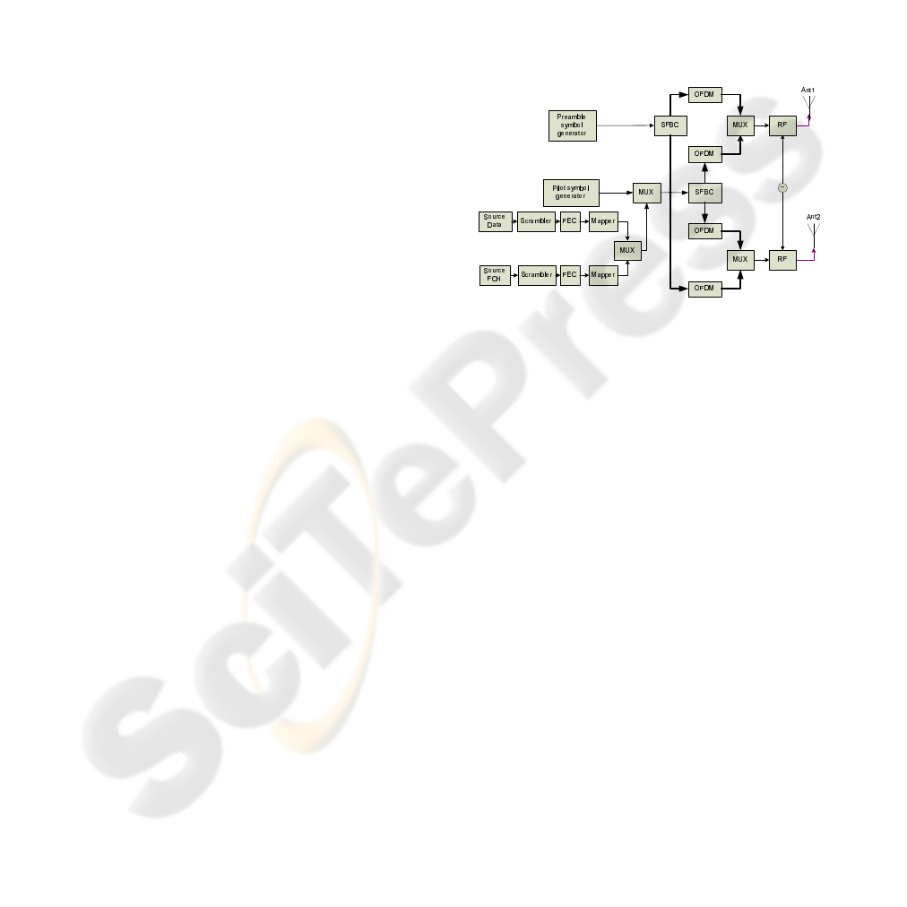
2 SYSTEM ARCHITECTURE
2.1 Transmission Scheme
The MIMO-OFDM transmitter with two branches
employing space-frequency block coding (SFBC) is
shown in fig.1. A binary data block D[k] of k
bits is scrambled, encoded by a concatenated Reed-
Solomon and Convolutional encoder, followed by a
puncturer and an interleaver. The resultant bit stream
is mapped using a set of predefined constellation di-
agrams (BPSK-1/2, QPSK-1/2, QPSK-3/4, 16QAM-
1/2, 16QAM-3/4, 64QAM-2/3, and 64QAM-3/4) giv-
ing a symbol stream S[m] of m symbols. The same
procedure is followed as well as for the frame control
header (FCH) (IEEE, 2004) with fixed QPSK map-
ping. These symbol streams are then frequency mul-
tiplexed with 8 pilot symbols and the output is SFB
coded based on Alamouti’s scheme. The output sym-
bols are packetized in blocks of 200 symbols, zero
padded and inserted in a 256-IFFT OFDM modula-
tor. Subsequently, the outputs are time multiplexed
with the OFDM output of the SFB coded preamble
symbols P . The produced digital signals at the two
chains are converted to analog ones and up-converted
to the carrier frequency through RF stages with com-
mon oscillator. Hence, time synchronization and fre-
quency offset compensation at the receiver are exactly
the same as in the case of a SISO system.
Figure 1: Transmitter Block Diagram.
2.2 Reception Scheme
At the receiver an equivalent procedure is followed.
Alamouti’s encoding scheme (Alamouti, 1998) (ap-
plied on a basis of 2 neighbor subcarriers) offers a
simple combining scheme assuming that the channel
estimates are available. Hence, extra attention has
been paid in the channel estimation stage as shown in
fig.2 (in which only one part of the 2 × 2 system has
been depicted). The received signal at the frequency
domain, either for data symbol stream, or for pream-
ble symbol stream at the receiver chain is expressed
as follows:
R
(m
R
)
i
=
M
T
X
j=1
H
(m
R
j)
i
· S
(j)
i
+ N
i
(1)
where i corresponds to the subcarrier index at the
m
R
-th receive antenna, j corresponds to the trans-
mitter antenna index out of M
T
transmit antennas
(M
T
= 2), N
i
corresponds to additive complex
Gaussian noise per subcarrier i with zero mean and
variance σ
2
n
. Also, H
(m
R
j)
i
corresponds to the chan-
nel coefficient between the j-th transmit antenna and
the m
R
-th receive antenna for the i-th subcarrier (Stu-
ber et al., 2004). The combiner outputs are fed to
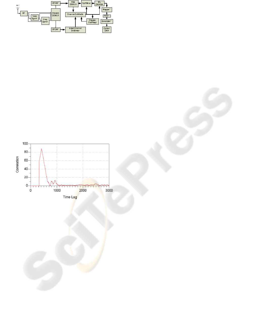
Figure 2: Receiver Block Diagram.
the maximum likelihood (ML) detector which esti-
mates the most probable symbol stream according to
the equation:
J = arg min
S
k
εC
=
N
c
−1
X
k=1
R
k
−
ˆ
H · S
k
2
(2)
where C = [S
0
, S
1
, , S
N−1
]. Time and frequency
synchronization are performed based on the time-
correlation properties of the relative preamble (fig.3).
The correction factor is fed back to the oscillator caus-
ing a delay. During this session, the analog automatic
gain control (AGC) is adapted and remains constant
during the subsequent frame period.
Figure 3: Correlation of time synchronization preamble at
the receiver.
2.3 Channel Models
The evaluation of SFBC MIMO-OFDM scheme has
been performed over realistic conditions taking into
account not only the channel propagation character-
istics, like time variability (Doppler shift) and multi-
path propagation (frequency selectivity), but also the
correlations between the antennas at the transmitter
and the receiver (described by Tx and Rx correla-
tion matrices). The physical parameters used for link
level modelling have been based on pedestrian level
of mobility with line of sight (Rice factor K=6dB) ac-
cording to the relative standard. Also, the proposed
correlation values have been taken into account for
an inter-element spacing of λ/2, where λ denotes the
wavelength.
3 CHANNEL ESTIMATION
Channel state information (CSI) is acquired by the re-
ceiver on a two-step procedure (fig.2) whereas no CSI
is fed back to the transmitter, establishing an open-
loop system with equal transmission power on the an-
tennas. The first step in the channel estimation pro-
cedure employs the OFDM preamble symbols which
are orthogonal on a SFBC subcarrier basis. The es-
timation has been implemented using a MMSE ap-
proach. In the second step, the pilot symbols are
used only for the phase estimation compensating the
Doppler distortion. Then, using interpolation the cor-
rection factor for each subcarrier is taken into account
in the preamble based estimation. The final channel
estimates are used for both channel compensation and
soft decision stages. Furthermore, Doppler estimation
gives a figure of merit of the channel’s time variation
which can be potentially used to increase the num-
ber of pilot data in time dimension or for adapting a
higher order interpolation filter.
The MIMO channel estimation problem can be de-
composed into several MISO channel estimations in
parallel (Stuber et al., 2004). The initial channel es-
timation is based on the preamble OFDM symbols
that have been transmitted from the 2 antennas in an
orthogonal space-frequency format. Taking into ac-
count only the adjacent subcarriers i and i + 1 that
convey pilot information in an orthogonal format it
will be:
R
(1)
i
= H
(11)
i
· S
(1)
i
+ H
(12)
i
· S
(2)
i
R
(1)
i+1
= H
(11)
i+1
· S
(1)
i+1
+ H
(12)
i+1
· S
(2)
i+1
R
(2)
i
= H
(21)
i
· S
(1)
i
+ H
(22)
i
· S
(2)
i
R
(2)
i+1
= H
(21)
i+1
· S
(1)
i+1
+ H
(22)
i+1
· S
(2)
i+1
(3)
where R
(m
R
)
i
is the received signal at m
R
-th receive
antenna in i-th subcarrier, H
(m
R
m
T
)
i
is the channel
coefficient from the m
T
-th transmit antenna to m
R
-
th receive antenna in i-th subcarrier, and S
(m
T
)
i
is the
transmitted symbol from m
T
-th antenna in i-th sub-
carrier. Since, the Alamouti scheme has been adapted
in space-frequency dimension the transmitted sym-
bols in i-th and (i + 1)-th subcarriers will be: P
a
=
S
(1)
i
, P
a
∗
= S
i+1
(1)
, P
b
= S
i
(2)
, −P
b
∗
= S
i+1
(2)
,
where (·)
∗
denotes the complex conjugate operation.
In addition, the channel is assumed constant for the
subcarriers i and i + 1 giving:
H
(11)
i
= H
(11)
i+1
= H
(11)
, H
(21)
i
= H
(21)
i+1
= H
(21)
H
(12)
i
= H
(12)
i+1
= H
(12)
, H
(22)
i
= H
(22)
i+1
= H
(2)
(4)
Hence, eq.3 becomes:
R
(1)
i
= H
(11)
· P
a
+ H
(12)
· P
b
R
(1)
i+1
= H
(11)
· P
∗
a
− H
(12)
· P
∗
b
R
(2)
i
= H
(21)
· P
a
+ H
(22)
· P
b
R
(2)
i+1
= H
(21)
· P
∗
a
− H
(22)
· P
∗
b
⇒
R
(1)
i
= H
(11)
· P
a
+ H
(12)
· P
b
R
(1)
∗
i+1
= H
(11)
∗
· P
a
− H
(12)
∗
· P
b
R
(2)
i
= H
(21)
· P
a
+ H
(22)
· P
b
R
(2)
∗
i+1
= H
(21)
∗
· P
a
− H
(22)
∗
· P
b
(5)
Expressing the above formula in matrix notation, it
will be:
R
(1)
i
R
(1)
∗
i+1
R
(2)
i
R
(2)
∗
i+1
=
H
(11)
H
(12)
H
(11)
∗
−H
(12)
∗
H
(21)
H
(22)
H
(21)
∗
−H
(22)
∗
·
P
a
P
b
⇔ R
p
= H
p
· S
(6)
where the index p denotes the processed nature of the
relative receive vector and the channel matrix. The
matrix H
p
has unitary properties, i.e.
H
H
p
· H
p
=
H
(11)
2
+
H
(12)
2
+
H
(21)
2
+
H
(22)
2
· I
2
= µ · I
2
(7)
where I
2
is the identity matrix of dimension 2, and
(·)
H
denotes the conjugate transpose matrix opera-
tion. For the case of perfect channel knowledge at
the receiver, the output of the combiner representing
the decision statistics (soft decisions) are given as fol-
lows:
˜
S =
1
µ
H
H
p
· R
p
=
1
µ
H
H
p
· (H
P
· S + N) ⇔
˜
S = S + N
m
(8)
which indicates that except the noise term the symbols
have been recovered at the combiner’s output. In a
real system the MIMO channel has been estimated at
the receiver non perfectly giving the following soft
decision metric:
˜
S =
1
µ
ˆ
H
H
p
· R
p
=
1
µ
ˆ
H
H
p
· (H
p
· S + N) ⇔
˜
S = H
res
· S + N
m
(9)
where the subscript res indicates the residual chan-
nel effect that have to be compensated by the ML de-
coder. In case of significant temporal channel varia-
tion during the transmission of an orthogonal scheme,
the orthogonality is lost causing intersymbol interfer-
ence. Hence, in order to preserve the orthogonality,
the sampling theorem has to be applied determining
the relative distances in time and frequency dimen-
sion that the pilots have to be placed. In space-time
block codes the distance is proportional to the coher-
ence time, while in space-frequency block coding is
proportional to the coherence bandwidth. The chan-
nel tracking is performed through the phase estima-
tion at the pilot positions based on the ML criterion
according to the equation:
ˆ
θ
c
= arg min
∠
ˆ
H
8
X
i=1
ˆ
H
i
·
ˆ
H
(pre)∗
i
(10)
where
ˆ
H
i
and
ˆ
H
(pre)
i
are the current channel esti-
mates at pilot positions and the estimates at the same
subcarrier i during the preamble OFDM symbol re-
spectively. The estimated phase difference updates
the preamble based estimation. The final channel es-
timates at the pilot positions are interpolated (linearly
in our case) in order to obtain the estimates in all sub-
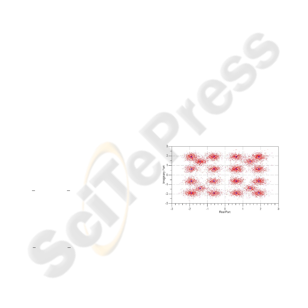
carriers. A sample of the channel compensated sym-
bols, just before the detector, is given in fig.4, where
the blue dots are the transmitted ones before the SFBC
encoder. The specific snapshot corresponds to a 2 × 2
MIMO-OFDM system with 16QAM and total cod-
ing (RS-CC) 3/4 in a channel type A (802.16e, 3GPP
standard) operating in E
b
/N
o
= 15dB. In addition,
QPSK modulation is observed due to the FCH sym-
bols. Quantitatively, the maximum achievable diver-
sity order is a product of the number of transmit anten-
nas, the number of receive antennas, and the number
of resolvable paths (Bolcskei and Paulraj, 2001).
Figure 4: Constellation map of the channel compensated
symbols (red) with respect to the transmitted ones (blue).
4 EVALUATION RESULTS
To study the impact of realistic channel estimation ar-
chitecture on MIMO-OFDM performance, a 2×1 and
2 × 2 MIMO-OFDM system with orthogonal space
frequency design has been designed, modelled and
simulated, taking into account all stages in RF, IF and
baseband level, as well as their relative requirements.
The simulated system achieves information data rates
of 6.9Mbps at BPSK-1/2, of 13.8Mbps at QPSK-1/2,
of 20.7Mbps at QPSK-3/4, of 27.7Mbps at 16QAM-
1/2, of 41.5Mbps at 16QAM-3/4, of 55.3Mbps at
64QAM-2/3, and of 62.2Mbps at 64QAM-3/4 in a
frequency bandwidth of 20MHz at a center frequency
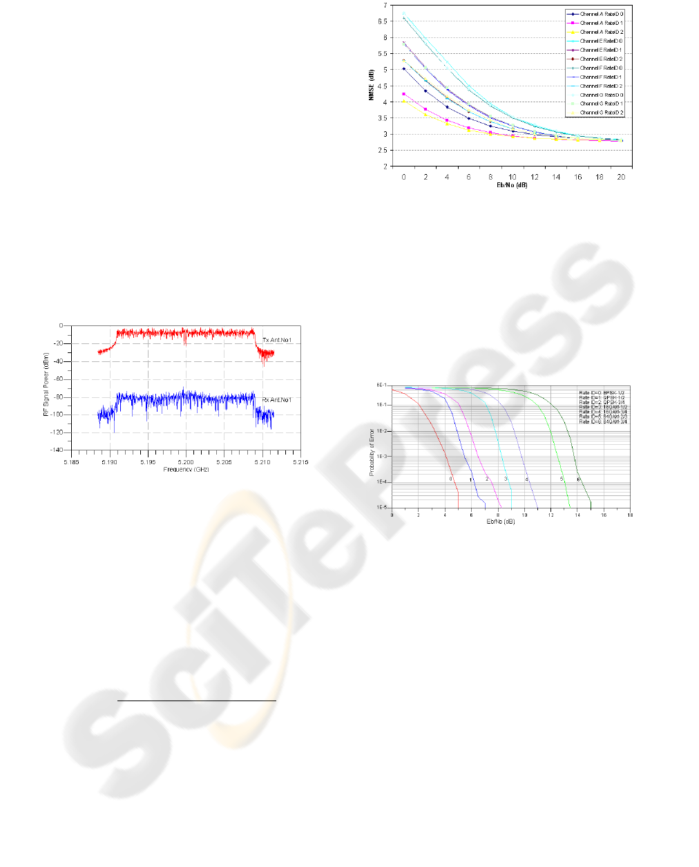
of 5.2GHz. The relative frequency spectrum at a
transmit antenna and a receive antenna is given in
fig.5 for the 16QAM-3/4 case in a propagation chan-
nel of type A (802.16e) and for E
b
/N
o
= 10dB. The
frequency selectivity is obvious, as well as the noise
distortion is becoming quite severe.
The channel adaptation is based on 8 pilot symbols
per OFDM symbol placed in blocks of 2 adjacent
subcarriers. OFDM stages are based on a 256-point
FFT/IFFT with cyclic prefix of 1/4. Each frame car-
ries 2400 information bits and the evaluation is per-
formed on the basis of achieving BER estimation rel-
ative variance of 0.0001 with an upper limit of 1000
frames. The performance of the channel estimator
Figure 5: Frequency spectrum at the Tx antenna (red) and
the corresponding Rx one (blue) for 2 × 2 OFDM system.
with respect to the actual channel propagation con-
ditions is based on normalized mean square error
(NMSE), according to the formula (11) and the re-
sults are given in fig.6 for the 2 × 2 MIMO-OFDM
case and for various propagation channels and data
rates. Based on these results the channel estimator
is characterized by an irreducible error floor at 3dB,
achieving the limit at E
b
/N
o
= 13dB for all schemes
and channel conditions tested.
NMSE =
E
H
(m
R
m
T
)
i
−
ˆ
H
(m
R
m
T
)
i
2
E
H
(m
R
m
T
)
i
2
(11)
The total system performance of 2 × 1 and 2 × 2
MIMO-OFDM system has been evaluated based on
the information bit error rate giving an insight at the
sensitivity of the channel estimation errors in the effi-
ciency of the system. For the probability of error P
e
measurement to be statistically significant, the rela-
tive variance R
v ar
of P
e
is taken into account for N
t
transmitted bits indicating the confidence interval of
P
e
. In fig.7 the probability of error has been produced
Figure 6: Normalized MSE of the overall channel estima-
tion in various propagation channels and data rates for 2 × 2
MIMO-OFDM case.
for 2× 1 case, in channel type A of 802.16e for all the
modulation formats and coding modes. It is worth
noticing that for the information data rate of 6.9Mbps
a value of E
b
/N
o
= 4.5dB is enough to achieve
P e = 10
−4
, while the same value for 62.2Mbps re-
quires almost 10dB increase in E
b
/N
o
. In fig.8 the
Figure 7: Probability of error for a 2 × 1 OFDM system in
propagation channel type A.
performance of a 2 × 1 OFDM system has been eval-
uated for various channel types of 802.16e standards.
The system performs better for channel type A, but
for more demanding channels (E,F,G), with higher
mobility or frequency selectivity, the system fails to
support increased data rates in relatively small val-
ues E
b
/N
o
. In fig.9 the performance of 2 × 2 MIMO
OFDM system has been depicted for various propa-
gation channels and data rates indicating that the pro-
posed scheme is quite efficient in propagation chan-
nels that follow the channel models of type A, E, or
G. Furthermore, the proposed scheme is characterized
by bit error rate achievable floors as E
b
/N
o
increases
in channel models with increased frequency selectiv-
ity.
Finally, for comparison reasons, the system has
been also implemented with space-time block coding
(STBC) and for the 2 × 1 OFDM case the results are
given in fig.10. The performance gain for the SFBC
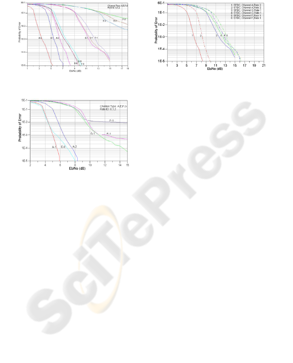
Figure 8: Perfromance of a 2 × 1 OFDM system in various
propagation channels and data rates.
Figure 9: Performance evaluation of a 2 ×2 OFDM system.
scheme at a probability of error P
e
= 10
−3
is about
2dB for a data rate of 20.7Mbps in a channel of type
A, whilst for 13.8Mbps the gain is about 1.5dB in
channels of types G and F.
5 CONCLUSIONS
In this paper a MIMO multicarrier system has been
designed and evaluated giving rise to space-frequency
orthogonality. In addition, all the RF stages at the
transmitter and the receiver were taken into account
approaching a real architecture as close as possible.
An efficient channel estimation scheme was incorpo-
rated in the system achieving not only a good effi-
ciency, but also low computational requirements since
the processing is performed in one OFDM symbol
and the channel estimation during the frame is limited
only in the varying propagation characteristics. The
overall system performance of SFBC MISO/MIMO
OFDM was evaluated for various propagation chan-
nels resulting in very good performances for propa-
gation conditions that are characterized by low fre-
quency selectivity, since the pilot overhead is only
3.12%.
Figure 10: Comparison between SFBC (solid) and STBC
(dash) schemes for 2 × 1 case.
REFERENCES
A. Adjoudani et al. “Prototype Experience for MIMO
BLAST Over Third-Generation Wireless System”,
IEEE Journal on Selected Areas in Communications,
Vol. 21, No. 3, pp. 440 - 451, April 2003.
V. Tarokh, N. Seshadri, A. Calderbank, “Space-Time Codes
for High Data Rate Wireless Communication: Perfor-
mance Criterion and Code Construction”, IEEE Trans
of Information Theory, vol.44, pp744-765, March
1998.
H. Bolcskei, A. Paulraj, “Space-Frequency Codes for
Broadband Fading Channels”, IEEE International
Symposium on Information Theory, pp. 219, June
2001.
V. Tarokh, H. Jafarkhani, A. Calderbank, “Space-Time
Block Codes for orthogonal designs”, IEEE Trans of
Information Theory, vol.45, pp1456-1467, June 1999.
Y. Li, N. Seshadri, S.Ariyavisitakul, “Channel Estima-
tion for OFDM Systems with Transmitter Diversity
in Mobile Wireless Channels”, IEEE Journal of Se-
lected Areas in Communications, vol.17,No3,p.461-
471, March 1999.
3GPP TR 25.996 v6.1.0, (2003-2009), “Spatial Channel
Model for Multiple-Input Multiple Output Simula-
tions”,
IEEE Std 802.16.2-2004, “Recommended Practice for Lo-
cal and metropolitan area networks”, 17 March 2004.
S. Alamouti, “A Simple Transmit Diversity Technique for
Wireless Communications”, Journal of Selected Areas
in Communications, vol.16, No8, October 1998.
G. Stuber J. Barry, S. Mclaughlin, Y. Li, M. Ingram, T.
Pratt, “Broadband MIMO-OFDM Wireless Commu-
nications”, Proceedings of the IEEE, vol.92, No2,
February 2004.
Agilent, “MIMO Wireless LAN PHY Layer [RF] Opera-
tion & Measurement, Application Note 1509”, 1509,
16/9/2005.
