
ADAPTIVE END-TO-END LOSS DIFFERENTIATION SCHEME FOR
TCP OVER WIRED/WIRELESS NETWORKS
Chang-hyeon Lim, Jin-hyuk Lee, Tae-hwan Kim, Woo-jin Han, Do-won Hyun and Ju-wook Jang
Department of Electronic Engineering, Sogang University
Shin-soo 1, Mapo, Seoul, Korea
Keywords:
Loss differentiation, Congestion control, TCP, Wireless.
Abstract:
We improve a well-known TCP throughput enhancement schemeover heterogeneous networks of wired/wiress
paths. The scheme (Westwood+) adjusts the congestion window using the estimate of currently available
bandwidth instead of halving the window in the event of a packet loss, enhancing the TCP throughput. Our
scheme infers the cause of packet loss(if it is due to congestion or regular bit errors over wireless paths) from
the changes of the RTT values. We adapt the RTT threshold used for determining the cause of packet loss
to the current congestion level. For example, we increase the RTT threshold for a packet loss to be regarded
as due to congestion when the congestion level of the path is estimated to be low. This avoids unnecessary
halving of the congestion window on packet loss due to regular bit errors over wireless path in a more precise
way than previous schemes. Compared with the Westwood+, our scheme improves the TCP throughputs by
29% and 55% on 1 Mbps and 10 Mbps paths, respectively. The fairness degradation is negligible.
1 INTRODUCTION
TCP congestion control runs under the basic assump-
tion that any packet loss is the indication of conges-
tion. However, the assumption does not hold when
the TCP flow path includes wireless part. In such a
case the packet loss may not come from congestion
but from regular bit errors over wireless path. TCP
throughput may be unnecessarily degraded due to the
packet loss from bit errors over wireless part even
though there is little congestion.
Known schemes to address this problem can be
divided into three categories(Sumitha, 2005): First,
network-based schemes locate an agent at the ac-
cess point/base station on the TCP path to locally
recover the wireless loss at transport or link layer.
M-TCP(MTCP, 1997) and I-TCP(ITCP, 1995) ap-
proaches split the TCP flow into the two parts at trans-
port layer and deal with the wireless part in differ-
ent way to improve the throughput. Network-based
schemes at transport layer do not maintain the end-
to-end semantics of TCP and may require state to be
maintained and packets to be buffered at the base sta-
This work was supported by the second-phase of Brain
Korea 21 Project in 2006.
tion. Snoop(Snoop, 1995) scheme places an observer
in the base station at link layer. However, it can be
purely local and aware of the semantics of the TCP
protocol.
In next, in the explicit loss notification approach
the receivers/network routers mark the acknowledge-
ments with appropriate notification of distinguish-
ing the channel errors from congestion losses. Then
the senders respond to the notification. In TCP-
Casablanca(Biaz, 2005), the sender sends packets
with different discard priorities. Routers drop marked
packets to de-randomize congestion losses. The re-
ceiver discriminates the cause of packet loss and
marks the acknowledgement with explicit loss noti-
fication. Then the sender responds to the notifica-
tion. Like TCP-Casablanca, the explicit loss notifica-
tion approaches require modifications to network in-
frastructure, the receiver, and the senders.
Finally, end-to-end schemes modify the TCP con-
gestion control algorithm to distinguish the losses
due to congestion in the network from other ran-
dom losses over wireless paths. They can be de-
ployed more easily because they are a modification
to the TCP congestion control at sender or receiver
side. Westwood+(West, 2004) is the best end-to-end
scheme as far as we know in terms of TCP throughput
129
Lim C., Lee J., Kim T., Han W., Hyun D. and Jang J. (2006).
ADAPTIVE END-TO-END LOSS DIFFERENTIATION SCHEME FOR TCP OVER WIRED/WIRELESS NETWORKS.
In Proceedings of the Inter national Conference on Wireless Information Networks and Systems, pages 129-136
Copyright
c
SciTePress
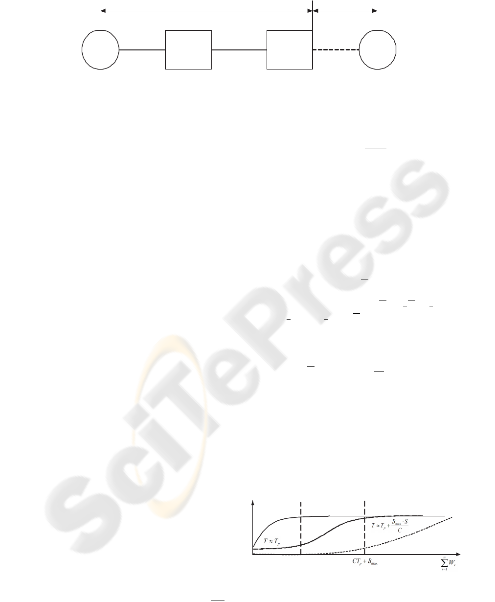
Sender R1 R2 Recv
50Mbps
20ms 10ms
d
B : buffer occupancy
C : link capacity
c
p
w
p
: Packet loss rate due to congestion
: Packet loss rate
over wireless part
Figure 1: The heterogeneous network model of wired/wireless paths.
enhancement. It estimates currently available band-
width and adjusts accordingly the congestion window
size instead of halving it in the event of a packet
loss. When three duplicate ACKs (TDACKs) are re-
ceived, both the congestion window (cwnd) and the
slow start threshold (ssthresh) are set equal to the esti-
mated bandwidth times the minimum measured RTT.
On timeout, the ssthresh is set as before while the
cwnd is set equal to one.
We propose a new end-to-end scheme which im-
proves the Westwood+. Instead of estimating the
available bandwidth, our scheme precisely infers the
cause of individual packet loss whether it is due to
congestion or regular bit errors of wireless nature.
The congestion window is reduced only when the
packet loss is determined to be due to congestion. A
moving threshold for relative change of RTT against
the minimum RTT is employed to differentiate the
cause of each packet loss. The moving threshold is
lowered to be more sensitive to congestion loss when
the network is is congested while it is increased when
the network is unloaded.
Compared with the Westwood+, our scheme im-
proves the TCP throughputs by 29% and 55% on 1
Mbps and 10 Mbps paths, respectively based on ns-2
simulations(NS-2). The fairness degradation is negli-
gible.
2 NETWORK MODEL
Figure 1 shows a heterogeneous network model of
wired/wireless paths to be used in the following de-
scription of our scheme. p
c
denotes the probability of
packet loss due to congestion in the wired path while
p
w
denotes a uniformly random packet loss probabil-
ity over the wireless path. Without loss of general-
ity, we assume there is no congestion over the wire-
less path. C denotes the link bandwidth in Mbps and
B denotes the number of packets(size S) currently
occupying the buffer. B
max
denotes the size of the
buffer. d denotes the propagation delay between the
base station(R2) and the receiver. Let T
p
denote the
propagation delay on the path between the sender and
receiver. The queuing delay is represented by
B·S
C
.
Then, the RTT(T ) can be written as Equation 1.
T = T
p
+
B · S
C
(1)
3 PROPOSED SCHEME
3.1 The Loss Differentiator
We present a new scheme to precisely infer the cause
of each packet loss encountered whether it is due to
congestion or not. The RTT(T ) measured immedi-
ately before the current packet loss is used through
Equation 2 as an indicator.
T and T
dev
are an expo-
nentialy weighted moving average of RTT(T ) and the
deviation. They are updated by T =
7
8
T +
1
8
T and
T
dev
=
3
4
T
dev
+
1
4
T −
T
as in most TCP imple-
mentations. The current packet loss is determined to
be a congestion loss if Equation 2 is satisfied.
T >
T + T
dev
·
2
T
p
T
k
− 1
!
(2)
The rationale behind the indicator represented by
Equation 2 can be better explained using Figure 2. It
shows the relationship among the buffer occupancy,
RTT and p
c
against
n
P
i=1
W
i
, the aggregate sum of the
congestion windows of the TCP flows established.
W
i
denote the congestion window size of i-th TCP
flow out of n flows.
p
CT
Link Utilization
RTT
Empty Build-up Overflow
c
p
Figure 2: Three-state of network buffer and the change of
the RTT with the aggregation of cwnd of each flow.
1 2 3 4 5 6 7 8 9 10
97
98
99
100
p
w
=1% :
p
c
=0 p
c
=3% p
c
=6%
p
w
=3% :
p
c
=0 p
c
=3% p
c
=6%
Ac (%)
k
(a)
1 2 3 4 5 6 7 8 9 10
30
40
50
60
70
80
90
100
p
w
=1% :
p
c
=0 p
c
=3% p
c
=6%
p
w
=3% :
p
c
=0 p
c
=3% p
c
=6%
Aw (%)
k
(b)
Figure 3: Accuracies of loss differentiator versus k for various network conditions.
When the buffer occupancy nears overflow, we
have T ≫ T
p
and the probabilty of congestion
loss(p
c
) becomes increasingly high. In order not to
miss any congestion loss, we decrease the threshold.
On the contrary, when T approaches T
p
, we increase
the threshold not to mistakenly count the wireless loss
as congestion loss. We estimated the accuracy of
the indicator against the value of k through a simu-
lation involving packet losses of known causes. A
c
is
the ratio of the number of congestion losses correctly
inferred over the total number of congestion losses.
A
w
is similarly defined for wireless losses. As k in-
creases, A
c
increases as shown in Figure 3(a), while
A
w
is decreased as shown in Figure 3(b). Thus k can
be chosen through trade-off analysis for best perfor-
mance in terms of throughput and fairness.
The thresholds in Zigzag scheme(Song, 2003) are
special cases of our indicator while they employ the
one-way delay approximately equal to half of the
RTT. The capability of our loss differentiation for
wireless losses is better by 100% than Zigzag scheme
while for congestion losses both schemes have the
same accuracy when only one flow is established.
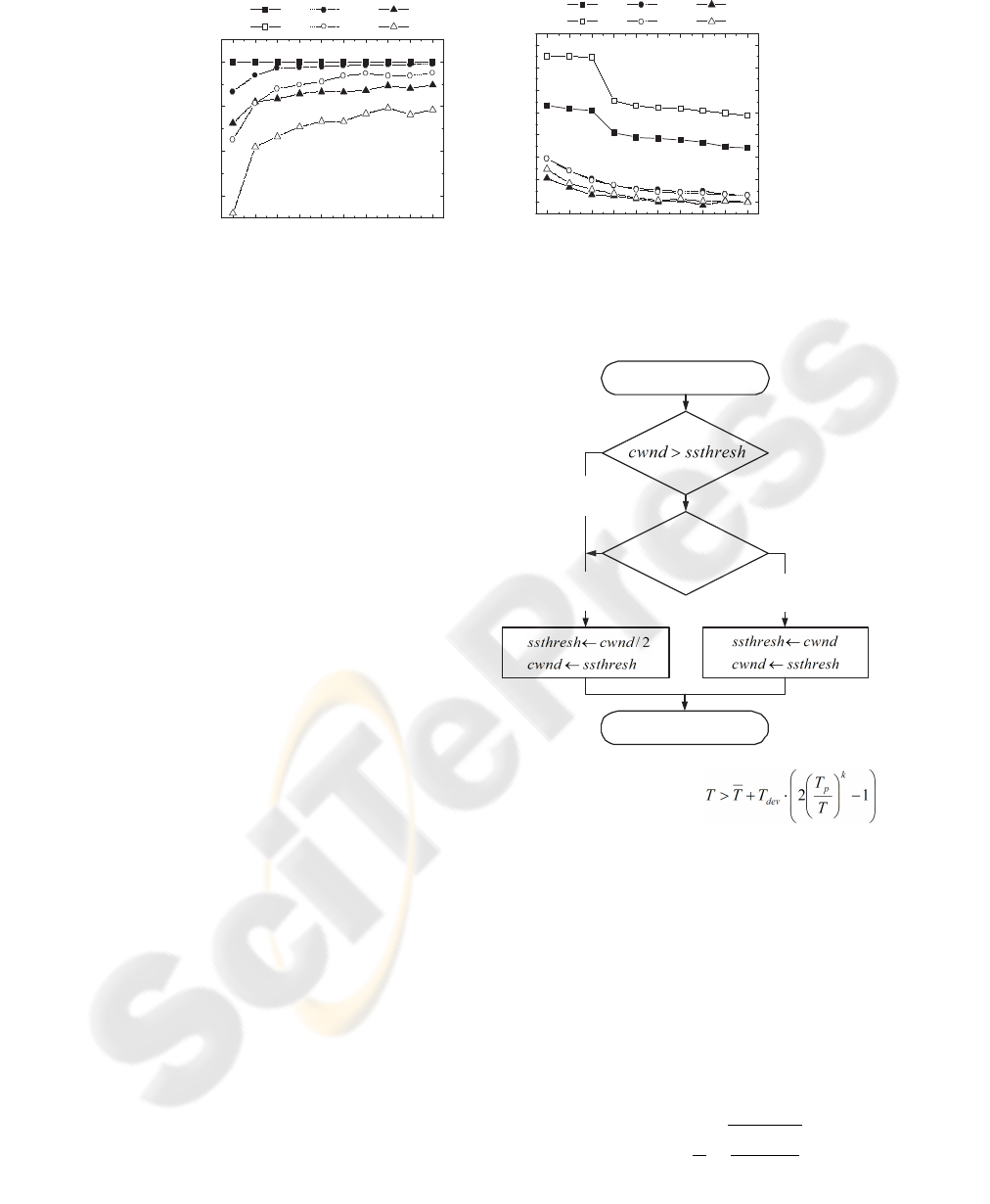
3.2 Tcp Modification
To apply the loss differentiator, we modify two blocks
in TCP congestion control: they are RTT update and
receipt of TDACKs. In RTT update, the TCP sender
updates the minimum of RTT which indicates the
propagation delay. On receipt of TDACKs, the sender
evaluates Equation 2 using the sample RTT measured
just before the TDACKs only if the TCP connection is
in the congestion avoidance phase. The sender halves
cwnd if Equation 2 is satisfied. Otherwise, the sender
keeps current cwnd. We explain the procedure of the
receipt of TDACKs in Figure 4.
No,
Slow-start phase
Yes, Congestion avoidance phase
Receipt of TDACKs
Retransmission
Yes,
Congestion loss
No,
Wireless loss
Congestion loss
Congestion loss : if
Figure 4: Flow chart for the modified congestion control
block.
3.3 Throughput Model
We derive the TCP throughput of the proposed
scheme following arguments developed by
Kelly(Kelly, 1999). The throughput model of
Westwood+(Luigi, 2002) is also derived similar to
(Kelly, 1999). The TCP throughput model can be
defined as Equation 3. For the simplicity, we do not
model the behavior after a timeout.
x
T CP
=
1
T
s
a(1 − p)
(1 − b)p
(3)
a and b denote the increase and the decrease para-
meter in TCP, respectively. p is the total packet loss
rate. Let x
prd
and b
prd
denote the throughput and
the decrease parameter of the proposed scheme, re-
spectively. x
ww+
and b
ww+
denote those of the West-
wood+, respectively. For both scheme, a is set to 1.
The decrease parameters(b
prd
and b
ww+
) derived
as a function can characterize the congestion control
of the proposed scheme and Westwood+, respectively.
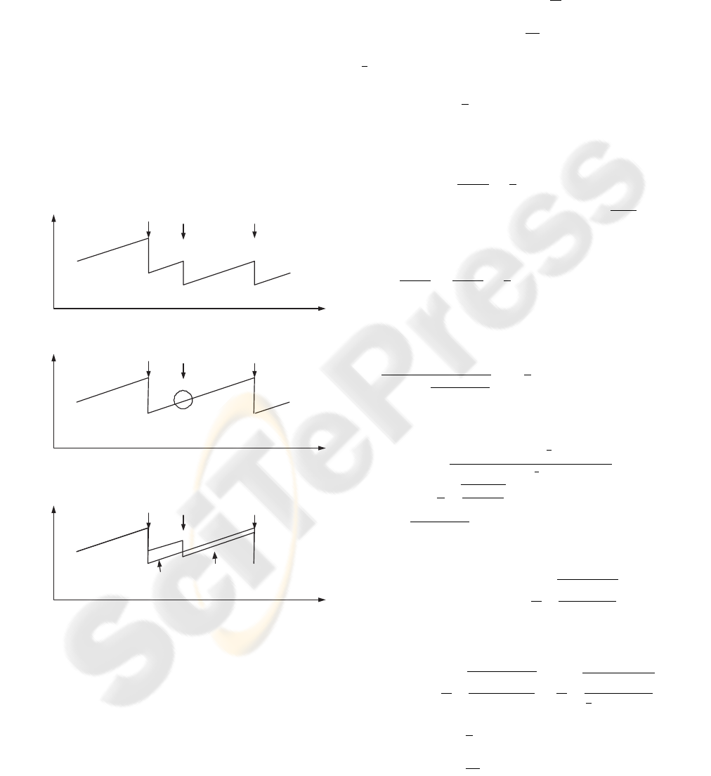
Figure 5(a) shows the change of cwnd in NewReno
over wireless paths. In this case, all of packet loss are
regarded as due to congestion. Figure 5(b) shows that
the proposed scheme infers the cause of packet loss
and keeps the current cwnd if the loss is regarded as
the wireless loss. Figure 5(c) shows that changing b
can be equivalent to the proposed scheme. We first de-
rive x
prd
similar to (Kelly, 1999) and (Luigi, 2002),
and then compare the proposed scheme with the West-
wood+ using b
prd
and b
ww+
.
time
cwnd
Reduction of cwnd by decrease
parameter, b=1/2, due to packet losses
(a) NewReno TCP
time
cwnd
Packet loss events
cwnd Increases with ignoring the
sign of packet loss by algotithms
(b) proposed scheme
time
cwnd
Proposed scheme
Change decrease parameter, b
Reduction of cwnd by decrease
parameter, b, due to packet losses
(c) equivalent model
Figure 5: The change of cwnd in (a) NewReno, (b) pro-
posed scheme, and (c) equivalent model of the proposed
scheme changing b.
The cwnd is updated upon ACK reception. Each
time an ACK is received back by the sender the cwnd
is increased by 1/cwnd. On the receipt of TDACKs,
the proposed scheme involves to infer the cause of
the packet loss. The cwnd is reduced by half if the
proposed scheme regards the packet loss as due to
congestion. Otherwise, the cwnd will be kept. Let
Pr(c|l) denote the probability of packet losses re-
garded as congestion losses. It results from the ag-
gregate sum of the probability to correctly detect the
congestion losses represented by
p
c
p
A
c
and the prob-
ability to wrongly infer the wireless loss into the con-
gestion loss represented by
p
w
p
(1 − A
w
) as shown
in Equation 4. Therefore, the change in cwnd is
1
2
· Pr(c|l) · cwnd.
Pr(c|l) =
1
p
[p
c
· A
c
+ p
w
· (1 − A
w
)] (4)
Since the total packet loss rate is p, it follows that the
expected change of cwnd per update step is:
E[∆cwnd] =
1 − p
cwnd
−
1
2
· Pr(c|l) · cwnd · p (5)
Since the time between update steps is about
T
cwnd
, by
recalling Equation 5, the expected change in the rate
x per unit time is approximately:
δx(t)
δt
=
1 − p
T
2
−
1
2
· Pr(c|l) · p · x
2
(t) (6)
Equation 6 is a separable variable differential equa-
tion. By separating variables, Equation 6 can be writ-
ten as:
δx(t)
x
2
(t) −
2(1−p)
T
2
·Pr(c|l)·p
= −
1
2
· Pr(c|l) · p · δt (7)
and by integrating each member the following solu-
tion can be obtained
x(t) =
x
1
· (1 + C
0
· e
−
1
2
·Pr(c|l)·p·t
)
1 − C
0
· e
−
1
2
·Pr(c|l)·p·t
where x
1
=
1
T
q
2(1−p)
Pr(c|l)·p
is the root of the equation
x
2
(t) −
2(1−p)
T
2
·Pr(c|l)·p
= 0 and a constant C
0
depends
on the initial conditions. The steady state throughput
of the proposed scheme is then,
∴ x
prd
= lim
t→∞
x(t) =
1
T
s
2(1 − p)
Pr(c|l) · p
(8)
and by recalling Equation 3 and 4, b
prd
can be written
as Equation 9.
x
prd
=
1
T
s
a(1 − p)
(1 − b
prd
)p
=
1
T
s
1 − p
1
2
Pr(c|l) · p
∴ b
prd
= 1 −
1
2
· Pr(c|l)
= 1 −
1
2p
[p
c
· A
c
+ p
w
· (1 − A
w
)] (9)
From Equation 9, the proposed scheme can adapt
b
prd
into p
c
since it increases A
w
as p
c
decreases(See
Figure 3). For example, b
prd
can be set to 1 when
p
c
≈ 0. However, b
prd
can approach
1
2
as p
c
in-
creases.
To compare with Westwood, the throughput ap-
proximation is shown as following (Luigi, 2002):
x
ww+
=
1
p
T (T − T
p
)
r
1 − p
p
(10)
By recalling Equation 3, b
ww+
can be derived as
Equation 11.
x
ww+
=
1
T
a(1 − p)
(1 − b
ww+
)p
=
1
T
1 − p
1 −
T
p
T
· p
∴ b
ww+
=
T
p
T
(11)
From Equation 11, we can find that the Westwood+
tries to empty the buffer to suppress the increase of
RTT since the b
ww+
is sensitive to the buffer occu-
pancy. Consequently, compared with Westwood+, the
proposed scheme can be expected to improve the TCP
throughput.
4 PERFORMANCE EVALUATION
4.1 Experimental Setup
We evaluate the performance of proposed scheme via
ns-2 (Ver 2.26)(NS-2) simulation. The network topol-
ogy is shown in Figure 1. The bottleneck (C in the
Figure 1) is set to 1 Mbps or 10Mbps. The size of the
buffer (B
max
) is set to the bandwidth-delay product
which is 12 packets or 120 packets, respectively. We
set the packet size equal to 1500 bytes. The value of k
is set to 2. We run simulations 50 times. In the each of
the 50 runs, we estimate the average throughput, link
utilization and fairness index. We use the Jain’s fair-
ness index(Jain, 1984) as in Equation 12 where x
i
and
n denote the throughput of i-th flow and the number
of flows, respectively. The Westwood+ module for
ns-2 is obtained from an official site(nsWestwood).
F (x) =
n
P
i
x
i
2
n
n
P
i
x
2
i
(12)
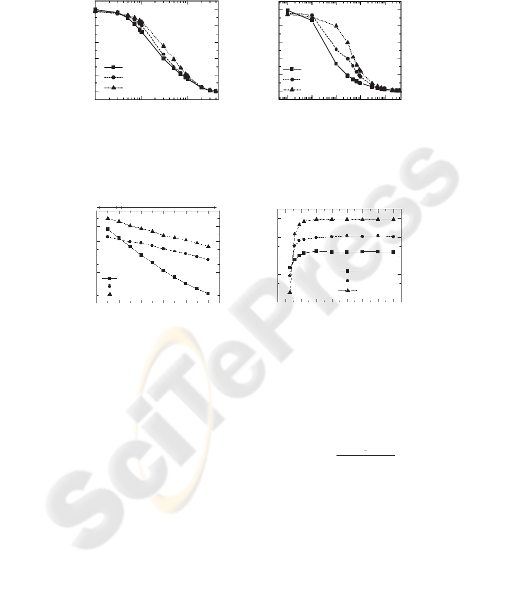
1 2 3 4 5 6 7 8 9 10
20
40
60
80
100
NewReno (1%)
Westwood+ (1%)
Proposed (1%)
NewReno (5%)
Westwood+ (5%)
Proposed (5%)
Link utilization (%)
the number of flows
(a) link utilization
1 2 3 4 5 6 7 8 9 10
0.92
0.94
0.96
0.98
1.00
NewReno (1%)
Westwood+ (1%)
Proposed (1%)
NewReno (5%)
Westwood+ (5%)
Proposed (5%)
Fairness index
the number of flows
(b) fairness index
Figure 6: Link utilization and fairness index on 1 Mbps of
bottleneck for p
w
= 1% and 5%.
4.2 Results
Figure 7 shows the throughput with increasing wire-
less packet loss rates. Compared with Westwood+,
the proposed scheme improves the throughput by up
to 29% and 55% when the bottleneck bandwidth is 1
Mbps and 10Mbps, respectively. Figure 6(a) shows
the link utilization with varying the number of flows
for 1% and 5% of wireless packet loss rates on 1 Mbps
link. The increase of wireless packet loss rate may
prevent the flows from fully utilizing the bottleneck
link capacity. Compared with Westwood+, the pro-
posed scheme improves the utilization by 0.1%-59%
depending on the number of flows. Figure 6(b) shows
that the fairness index of the proposed scheme stays
over 0.995 which is similar to those of Westwood+
and NewReno.
Figure 8(a) shows the TCP throughput decreases
as wireless propagation delay(d) increases (C=1Mbps
and p
w
=1%). The NewReno suffers most as high as
47.5% when the delay increases from 10ms to 100ms.
While the throughput of the Westwood+ and the
0.1 1 10
0
2
4
6
8
10
NewReno
Westwood+
Proposed
Throughput (x100kbps)
Wireless loss rate (%)
(a) 1Mbps
1E-3 0.01 0.1 1 10
0
2
4
6
8
10
NewReno
Westwood+
Proposed
Throughput (Mbps)
Wireless loss rate (%)
(b) 10Mbps
Figure 7: Throughput comparisons with Westood+ and NewReno.
0 20 40 60 80 100
4
5
6
7
8
9
10
NewReno
Westwood+
Proposed
Throughput (x100kbps)
d (ms)
WLAN Cellular / Satellite
(a) Delay
0 10 20 30 40 50 60 70
5
6
7
8
9
NewReno
Westwood+
Proposed
Throughput (x100kbps)
B
max
(packets)
(b) Buffer size
Figure 8: Throughput comparisons with Westood+ and NewReno versus change of delay and buffer length.
proposed scheme decrease 17.6% and 19%, respec-
tively, the proposed scheme improves the throughput
by 11.5% - 14.5% compared with the Westwood+.
Figure 8(b) shows the TCP throughput as B
max
in-
creases. When B
max
≧ 6 packets, the proposed
scheme improves the throughput as shown above.
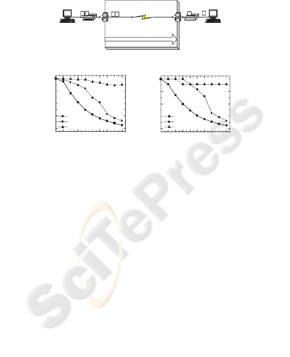
4.3 Implementation and results
We implement the algorithm based on Linux Kernel
Ver. 2.4.20 as shown in Figure 9(a). The sender runs
a FTP client and the receiver runs a FTP server. The
data flow is sent through the Nist Net(NIST). We set
50 packets to the maximum buffer size and 70ms to
forward path delay, and we vary the wireless packet
loss rate from 0% to 9%. We record the goodput de-
fined as Equation 13 for 3MB and 100MB of file size.
We uploads a file of size 3MB 10 times. As shown
in Figure 9(b) and 9(c), the proposed scheme have the
best goodput with increasing the wireless packet loss
rate.
Goodput(%) =
file
size
duration × C
× 100(%) (13)
5 CONCLUSION
We propose a simple TCP modification to improve the
Westwood+ through precise inferring of the cause of
packet losses. The proposed scheme is an end-to-end
scheme which is easy to implement. Modifications is
made only to the TCP sender. From the simulation
results, an adaptative loss differentiator can improve
the throughput compared with Westwood+, and the
degradation of fairness is negligible. Westwood+ can
Drop (%)
Wireless link
Random loss
Propagation (ms): Delay,
Delsigma (Delay Variance)
Bandwidth (byte/second)
p p
p p
p
p
100Mbps Hub
100Mbps
Switch
Eth1: 192.168.1.1
Private Network
Eth0: 163.239.162.118
Campus Network or LAN
Sender
(FTP Client)
Receiver
(FTP Server)
Nist Net
(a) NistNet setup
0 1 2 3 4 5 6 7 8 9
20
40
60
80
100
NewReno
Westwood+
Proposed
Goodput (%)
Drop (%)
(b)
0 1 2 3 4 5 6 7 8 9
20
40
60
80
100
NewReno
Westwood+
Proposed
Goodput (%)
Drop (%)
(c)
Figure 9: (a) Emulation setup using NistNet and goodput for (a) 3MB and (b) 100MB file.
estimate the available bandwidth less than the real one
due to frequent wireless losses. Thus, it may fail to re-
tain the current cw nd. However, the proposed scheme
can retain the current cwnd through more precise in-
ferring of the cause of packet losses. Our scheme is
more effective in improving the throughput especially
when the bottleneck bandwidth is high(Compare Fig-
ure 7(a) and 7(b)).
REFERENCES
Luigi A. Grieco, and Saverio Mascolo, ”Performance Eval-
uation and Comparison of Westwood+, New Reno,
and Vegas TCP Congestion Control”, ACM Computer
Communication Review, 34(2): pp25-38, April 2004
Saad Biaz and Nitin H. Vaidya, ””De-randomizing Con-
gestion Losses” to Improve TCP Performance over
Wired-Wireless Networks”, ACM/IEEE Transactions
on Networking, Vol. 13, No. 3, June 2005, pp596-608
Song Cen, Pamela C. Cosman, and Geoffrey M. Voelker,
”End-to-End Differentiation of Congestion and Wire-
less Losses”, IEEE/ACM Transactions on Network-
ing, Vol. 11, No. 5, Oct. 2003, pp703-717
Sumitha Bhandarkar, Nauzad Erach Sadry, A.L. Narasimha
Reddy, and Nitin H. Vaidya, ”TCP-DCR: A Novel
Protocol for Tolerating Wireless Channel Errors”,
IEEE Transactions on Mobile Computing, Vol. 4, No.
5, pp517-529, Sep. 2005
TCP Westwood+ modules for ns-2. http://193.204.59.68/
mascolo/tcp%20westwood/modules.htm
NS-2 network simulator (ver 2). LBL, http://www-
mash.cs.berkeley.edu/ns
National Institute of Standards and Technology, “NIST
Net”, http://www.antd.nist.gov/itg/nistnet
R. Jain, D.M.Chiu and W.Hawe, ”A Quantitative Measure
of Fairness and Discrimination of Resource Alloca-
tion in Shared Systems”, Technical Report, Digital
Equipment Coporation, DEC-TR-301, 1984
Frank Kelly, ”Mathematical Modeling of the Internet”, Pro-
ceedings of the Fourth International Congress on In-
dustrial and Applied Mathematics, 1999, pp105-116
Luigi Alfredo Grieco and Saverio Mascolo, ”TCP West-
wood and Easy RED to improve Fairness in High-
Speed Networks”, 7th International Workshop on Pro-
tocols for High-Speed Networks (PfHSN’2002), April
22-24, 2002, Berlin, Germany.
Kevin Brown and Suresh Singh, “M-TCP: TCP for Mobile
Cellular Networks”, ACM SIGCOMM 97, Cannes,
France, July. 1997
Ajay Bakre and B. R. Bandrinath, “I-TCP: Indirect TCP
for Mobile Hosts”, Proceedings of the 15th Interna-
tional Conference on Distributed Computing Systems
(ICDCS ’95), pp 136˜143, Vancouver, May, 1995
Hari Balakrishnan, Srinivasan Seshan, and Randy H. Katz,
“Improving Reliable Transport and Handoff Perfor-
mance in Cellular Wireless Networks”, In ACM Wire-
less Networks Journal, 1(4), Dec. 1995
