
ACK RATE CONTROL STRATEGY AT THE LINK LAYER TO
ENHANCE TCP OVER 3G LINKS
Juan J. Alcaraz, Fernando Cerdán
Department of Information Technologies and Communications, Polytechnic University of Cartagena, Plaza del Hospital 1,
30202 Cartagena, Spain
Keywords: TCP over 3G, Radio Link Control (RLC).
Abstract: When TCP is carried over 3G links, overbuffering and buffer overflow at the RLC layer degrades its
performance. In order to prevent these undesired cross-layer interactions, we propose an algorithm to
control the rate of the acknowledgements (ACK) traversing the RLC entity at the network side. Since the
sending rate of a TCP source is determined by the arrival rate of the ACKs, the basic idea of this scheme is
to adjust the inder-departure time of the ACKs in the uplink direction, according to the congestion level of
the downlink buffer. By means of extensive simulation experiments, we disclose the influence of each
parameter on TCP performance. We provide several configurations that improve end-to-end goodput while
reducing the delay. The operation of the algorithm is deterministic; it does not require changes in 3G
specifications nor in TCP itself, and preserves TCP end-to-end semantics.
1 INTRODUCTION
Third generation cellular networks (3G) are
expected to be an important part of the Internet.
Many Internet applications like e-mail, web surfing
and file transfer, rely on TCP for the end-to-end
transport. In 3G radio access networks, the link layer
is managed by the Radio Link Control (RLC)
protocol (3GPP, 2005). For packet switched
services, RLC is usually configured to provide a
reliable service, recovering from propagation errors.
A reliable RLC layer reduces packet losses
perceived at TCP layer, avoiding the triggering of
unnecessary congestion control measures
(Inamura, 2002).
Although, in general, RLC improves TCP transfer
rate over a radio bearer (RB), several characteristics
of 3G links like high and variable latency and buffer
overflow of the RLC downlink buffers (Alcaraz,
2006), have undesired effects on TCP performance.
One of the strategies to overcome these effects is
to improve the RLC layer. In contrast to other
proposals, like split-connection proxies, this
approach does not require changes in the TCP itself
and does not break the end-to-end semantics of TCP.
Several works propose the use of Active Queue
Management (AQM) techniques in the RLC
downlink buffer. It was shown in (Alcaraz, 2006)
that these mechanisms can enhance TCP goodput
while reducing end-to-end latency. A slightly
different approach is the use of ACK Delay Control
at RLC. This mechanism was presented in (Wu,
1999) as an algorithm to improve the performance of
TCP over satellite links. The underlying idea is to
delay acknowledgements travelling through a node
where its forward connection is congested. Since the
ACK arrival rate at a TCP source determines the
sending rate of new packets, this is a simple
mechanism to reduce packet drops due to buffer
overflow. The congestion is detected when the
buffer occupancy exceeds a fixed threshold (minth).
When this happens a delay is applied to the ACK
packets in the reverse flow to slow down its
departure rate. This mechanism takes advantage of
the TCP self-clocking principle, as the reduction in
the ACK flow rate will reduce the sending rate of
the source. In the original proposal the delay applied
to ACKs is a constant value.
In this paper we propose an adaptation of this
algorithm for 3G links, where ACK rate is adapted
according to the downlink queue length. We
consider a general delay computing function, in
which the fixed delay and the linear relation are
particular cases. This generalization gives us a wider
point of view to find optimum configurations. We
34
J. Alcaraz J. and Cerd
´
an F. (2006).
ACK RATE CONTROL STRATEGY AT THE LINK LAYER TO ENHANCE TCP OVER 3G LINKS.
In Proceedings of the International Conference on Wireless Information Networks and Systems, pages 34-42
Copyright
c
SciTePress
provide a feasible implementation of the algorithm,
and by means of extensive simulation tests, we
discuss the influence of each parameter and propose
configurations that clearly improve end-to-end
performance compared to the conventional RLC
operation.
The rest of the paper is organized as follows.
Section 2 describes the characteristics of the 3G
radio bearer that degrade TCP performance.
Section 3 explains our ACK rate control algorithm
in detail. Section 4 provides a brief description of
the simulation environment. Section 5 discusses the
influence of each parameter in end-to-end
performance based on extensive simulation results.
The paper concludes in section 6.
2 MOTIVATION
Previous experimental (Chakaravorty, 2005) and
simulation (Rossi, 2003) results provide a clear view
of the characteristics of 3G wireless links. The
behaviour of the link buffer occupancy has shown a
great impact on TCP performance.
3G links employs per-user buffering. Flows going
to a single mobile terminal share a single buffer.
Therefore, radio bearers are expected to multiplex a
number of simultaneous connections ranging form 1
to 4 TCP flows (Gurtov, 2004). At a reliable RLC
layer, the upper layer packets will be stored in the
downlink buffer until they are fully acknowledged
by the receiver side. The consequence is that, as
described in (Bestak, 2002) frame losses in the
downlink channel result in higher RLC buffer
occupancy at the network side. Considering that the
current RLC specification propose a drop-tail
scheme, the buffer may overflow causing
consecutive packet losses. This situation is
especially harmful in the first stages of a TCP
connection (slow start) and has a higher impact in
TCP Reno, which can only recover from consecutive
losses with a Retransmission TimeOut (RTO). An
RTO reduces TCP transmission window to one,
causing the highest reduction of the source rate.
The buffer should be large enough to avoid
frequent overflow. However, excessive queuing
causes some additional problems (Chakaravorty,
2005) like Round Trip Time (RTT) inflation,
unfairness between competing flows and viscous
web surfing.
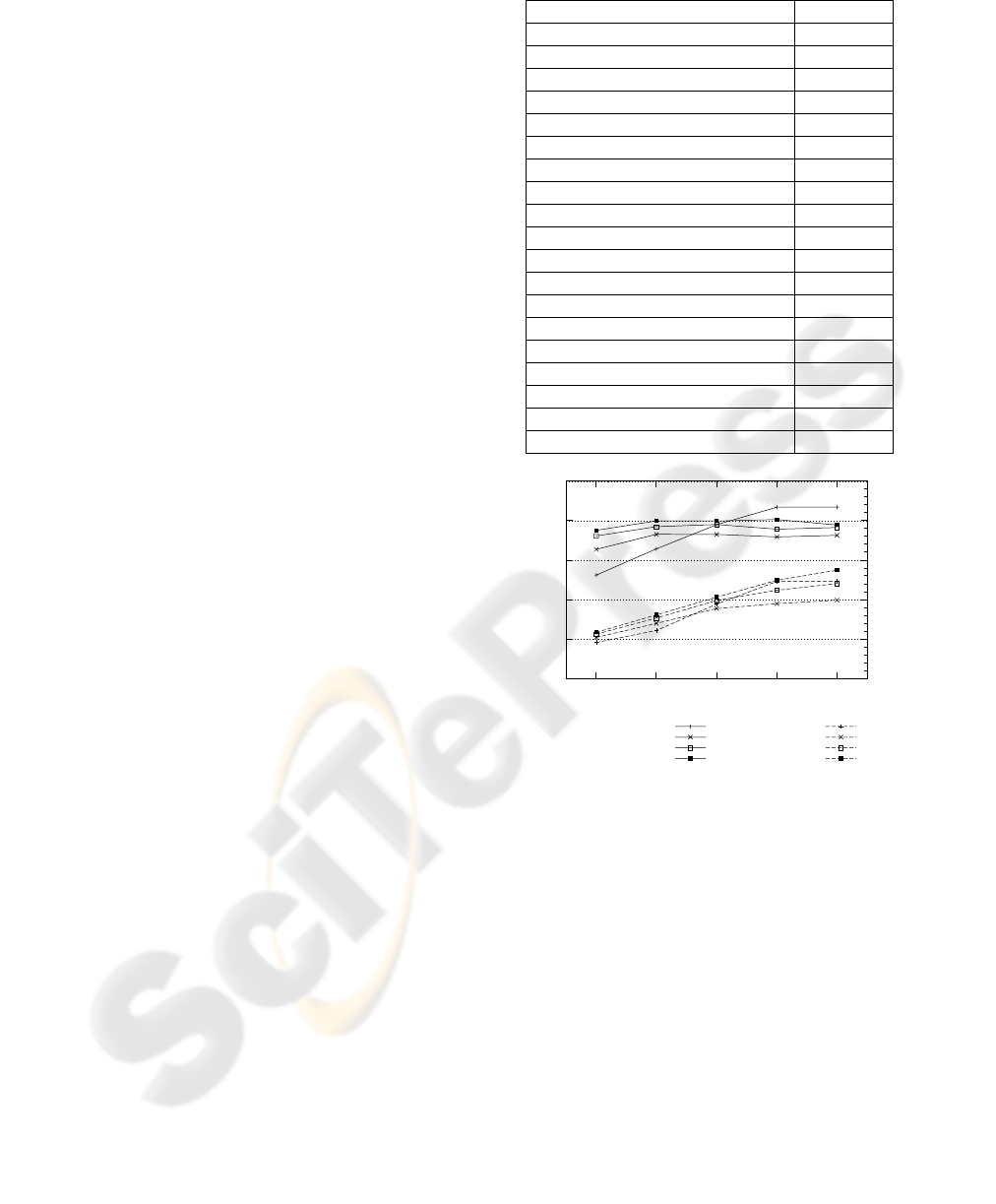
Fig. 1 illustrates the end-to-end goodput and
delay of TCP over an RB for different RLC buffer
sizes and a number of flows ranging from 1 to 4.
The goodput accounts for the successfully delivered
packets at the receiver and the delay is the transfer
time of a packet in the downlink direction, at the
TCP layer. The buffer size is given in RLC Service
Data Units (SDU) of 1500 bytes. Table 1 shows the
parameter configuration for the RLC and TCP
protocols. The RLC parameters were set according
to the optimizing considerations described in
(Alcaraz, 2006) and (Rossi, 2003). Further details on
the simulator are provided in section 4. As expected,
Fig. 1 reveals that a larger buffer benefits the
goodput performance but the overbuffering increases
the latency.
Fig. 2 shows the trace of a TCP connection over a
384 kbit/s radio bearer multiplexing one TCP flow.
The curve at the top shows the RLC buffer
occupancy (BO). The buffer size is limited to 50
SDUs. The TCP congestion window (cwnd) is
depicted under this curve, and the curve at the
bottom shows the sequence number of the packets
when they are sent, received and dropped.
100
150
200
250
300
350
30 40 50 60 70
0
0.5
1
1.5
2
2.5
Goodput (Kbit/s)
End-to-end delay (s)
Buffer Size (SDUs)
goodput 1 flow
goodput 2 flows
goodput 3 flows
goodput 4 flows
delay 1 flow
delay 2 flows
delay 3 flows
delay 4 flows
Figure 1: TCP performance over a 384 kbit/s RB.
Table 1: Simulation Parameters
3G link parameters Setting
PDU payload size 320 bits
TTI (Transm. Time Interval) 10 ms
Transmission window 1024 PDUs
maxDAT 10
In-order-delivery true
Status Prohibit Timer 60 ms
Missing PDU detection true
Poll Timer 60 ms
Wireless Round Trip Delay 50 ms
Normalized doppler frequency 0,01
Poll window 50 %
Last PDU in buffer Poll yes
Last retransmitted PDU Poll yes
Frame Error Ratio (FER) 10%
TCP parameters Setting
Maximum TCP/IP packet size 1500 bytes
Maximum allowed window 64 kbytes
Initial window 1
Wired Network Round Trip Delay 200 ms
ACK RATE CONTROL STRATEGY AT THE LINK LAYER TO ENHANCE TCP OVER 3G LINKS
35
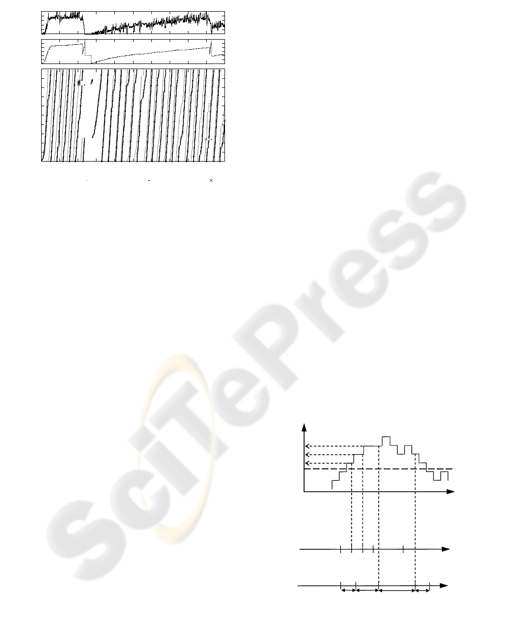
At the first stages of the connection, multiple
packets are dropped due to buffer overflow, causing
an RTO. The buffer is drained because the
connection reduces its rate, with the consequent
underutilization of the resources. After that, the rate
is recovered slowly and the overbuffering appears
again, causing high delay and additional
packet losses.
3 PROPOSED ALGORITHM
TCP is basically a sliding window algorithm. The
transmission window limits the total amount of data
that the source can transmit without receiving any
acknowledgement from the receiver side. The
window moves forward and its length increases with
the arrival of ACKs, thus the source can inject new
segments in the network. This is usually called TCP
self-clocking mechanism.
In this paper we propose a scheme for controlling
the rate at which TCP ACKs cross the RLC layer.
Since the throughput of a TCP source is basically
determined by the arrival rate of ACKs, it is possible
to avoid overbuffering and buffer overflow in the
RLC layer if this rate is conveniently adapted to the
link situation. The buffer occupancy (BO) is the
variable used to perceive the link quality, and the
rate control measures are applied only when certain
BO threshold is reached (minth). In our algorithm,
the inter-departure time, t
id
, of ACKs traversing the
RLC layer is computed with a non-linear function of
BO, t
id
= f(BO), which is obviously a continuous and
only-increasing function because the rate has to be
reduced when the BO increases.
The motivation of the variable delay strategy is to
gradually adapt the source’s perception of the
0
10
20
30
40
50
60
70
80
90
100
0 10 20 30 40 50 60 70 80 90 100
Sequence Number
Time (s)
data sent data rx drop
10
20
30
40
50
60
cwnd
0
10
20
30
40
50
BO
Figure 2: TCP trace over a 384 kbit/s RB.
for each event
if (event == ack_arrival)
insert ack in uplink buffer
if (event == id_timer_expiration)
send first ack in buffer
LADT Åcurrent_time
if (uplink buffer nonempty)
and(id_timer off)
delay Å 0
if (BO>=
minth)
t
id
= f(BO)
actual_t_id Åcurrent_time – LADT
if (actual_t_id <
t
id
)
delay Å
t
id
− actual_t_id
if (delay == 0)
send ack
LADT Åcurrent_time
else
id_timer Å delay
activate id_timer
Events:
ack_arrival: arrival of an upcoming ACK
id_timer_expiration: expiration of the
id_timer
Saved Variables:
LADT: Last Ack Departure Time
Other:
current_time: system clock
delay: artificial delay applied to
outgoing ACKs
Figure 4: Proposed ACK rate control algorithm.
B
O
ACK’s
arrival
time
ACK’s
departure
time
12
3
4
5
1
2
3
45
1id
t
2id
t
2id
t
3id
t
1
BO
2
BO
3
BO
)(
nidn
BOft =
nthmi
t
t
t
Figure 3: TCP performance over a 384 kbit/s RB.
WINSYS 2006 - INTERNATIONAL CONFERENCE ON WIRELESS INFORMATION NETWORKS AND SYSTEMS
36

available bandwidth and the round trip delay. Higher
buffer occupancies require higher reductions in the
sending rate of the source, while for a short error
burst an excessive delay on the ACKs could be
unnecessary. This should also help to avoid
excessive delay spikes causing spurious TCP
timeouts.
It may be argued that a drawback of the ACK
delaying strategy is the Retransmission Time Out
(RTO) inflation caused by the increment on the
perceived RTT. The RTO inflation slows down the
reaction of the source upon the eventual loss of
consecutive packets. However, the higher delay of
the reverse path is compensated by a lower buffer
occupancy, which reduces the downlink packet
latency. In addition, a main goal of this algorithm is
the avoidance of buffer overflow, thus TCP timeouts
are expected to happen rarely.
The proposed ACK rate control algorithm is
detailed in Fig. 3. The algorithm relies in the use of a
single timer (id_timer), which delays ACKs assuring
that they are spaced by t
id
. The pseudocode identifies
two different events, the arrival of an ACK packet
(ack_arrival) and the expiration of the id_timer
(id_timer_expiration). Figure 4 illustrates the
operation of the algorithm.
3.1 Calculating the Inter-departure
Time
The original proposal for controlling the rate of the
reverse ACK flow relies on a fixed delay (Wu,
1999). This strategy may be enhanced using a
variable delay, e.g. setting a linear relation between
the delay and the downlink queue length.
In this paper we consider a more general function
(1) to estimate t
id
with BO, where maxd and mind are
the maximum and minimum values for t
id
, and maxth
is the buffer size.
ndmi
nthmixthma
nthmiBO
ndmixdmat
id
+
⎟
⎟
⎠
⎞
⎜
⎜
⎝
⎛
−
−
−=
α
)(
This function let us evaluate the effect of the
variation rate of t
id
respect BO. This variation rate,
which is related to the “aggressiveness” of the
algorithm, is determined by
α
(≥0). Lower values of
α
are tied to more aggressive delaying policies.
Figure 5 shows the shape of (1) for different values
of
α
. From now on, to reduce complexity, we
consider mind = 0 s. The shape of f(BO) with
mind > 0, can be approximated using f(BO) with
mind = 0 and a lower
α
. In consequence, in out tests,
the value of mind showed very little influence on
performance.
In (1) it is easy to see that, if
α
Æ 0, f(BO) tends
to the step function, i.e. t
id
is constant when
BO ≥ minth. On the other hand, if
α
= 1, f(BO) is a
linear function. Therefore, the step and the linear
functions are particular cases of (1). Moreover, the
absence of delay is also a particular case of this
function, when
α
Æ ∞. These cases are discussed
in Section 5.
3.2 Implementation Issues
An important advantage of the ACK delay control
algorithm compared to random or RED-like
mechanisms is that it does not need to generate
random numbers to compute the discarding
probability because of its deterministic operation.
This reduces the computational cost of the
algorithm, and makes it more feasible for its
implementation at the RLC level where the buffering
is done in a per-user basis.
The maintenance of a new timer, id_timer, does
not add too much complexity to the RLC operation,
which already handles several timers, e.g. Poll
Timer and Status Prohibit Timer (3GPP, 2005). The
RLC can synchronize id_timer to the Transmission
Time Interval (TTI), which is equivalent to a clock
signal with a granularity of 10 ms (similar to that of
other RLC timers).
The protocol could be further simplified in terms
of implementation with the use of pre-calculated t
id
values. Therefore, the buffer could be considered as
divided in gaps, each one having a corresponding t
id
value. In our implementation, the number of t
id
values equals the number of SDUs fitting in the
buffer space above minth.
Our implementation does not deal with ACK
identification, because the services considered to
benefit from our algorithm are assumed to be
strongly asymmetric, e.g. file downloading and web
browsing. Therefore, in our simulations, every
upcoming packet is an ACK. However, a simple
way to implement IP packets monitoring and ACK
filtering is described in (Wu 1999). It is a subject of
further research if, given the traffic profile of a 3G
user, an ACK filtering mechanism is justified.
4 SIMULATION ENVIRONMENT
The simulation environment for this research has
been developed in OMNeT++ (Varga, 2001) and
comprises a complete implementation of TCP and
RLC protocols. Similar simulators were described in
(Rossi, 2003) and (Bestak, 2002). The simulation
topology, shown in Fig. 6 consists of one or several
TCP sources connected to their respective receivers
in the user’s equipment (UE). The end-to-end
connection consists of two sections, the wired
ACK RATE CONTROL STRATEGY AT THE LINK LAYER TO ENHANCE TCP OVER 3G LINKS
37
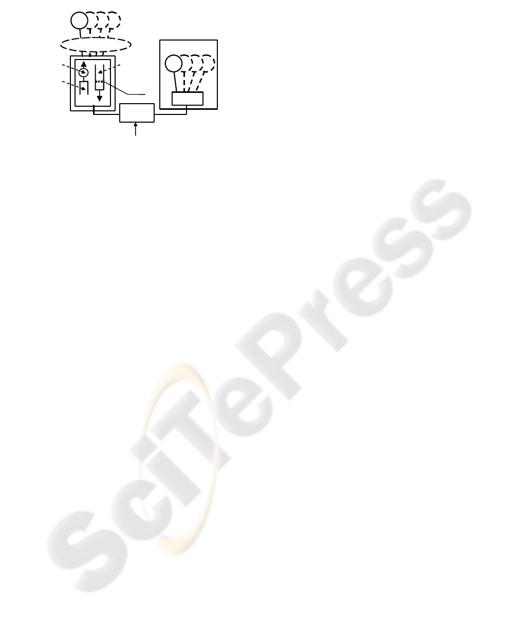
network and the radio bearer. The wired network
comprises the Internet and the 3G core network. The
radio bearer has a round trip time (RTTw) of 50 ms
(Holma, 2004) and a nominal transmission rate
equal to 384 kbit/s in both directions, representing
the bottleneck link, which is the situation expected
in most cases (Gurtov, 2004). The wired network is
modeled with a 1 Mb/s link with a round trip delay
(RTTf) of 200 ms.
The wireless channel generates error bursts
according to the model described in (Chockalingam,
1999) where the Doppler frequency, f
d
, of the UE
determines the average burst length. Lower f
d
causes
longer bursts of errors. It is usual to employ the
normalized Doppler frequency, equal to the product
of f
d
and the radio frame duration (10 ms).
In order to obtain more realistic results, the error
probability is the same in the uplink and in the
downlink direction. The frame loss ratio is 10%, a
typical UMTS design value (Meyer, 2003).
The simulation results exposed in this paper are
obtained averaging 20 runs per sample. Each run is a
60 second download session. The confidence
intervals are obtained with a confidence degree of
90% according to a t-student distribution.
The TCP flavour employed is TCP Reno, one of
the most extended in the Internet (Gurtov, 2004).
RLC and TCP parameter setting is shown in Table 1.
5 PERFORMANCE EVALUATION
In order to disclose the effect of each parameter in
end-to-end performance, multiple parameter
combinations were tested: The values of
α
ranged
from 0 to 40; for minth, the following values were
evaluated: 0, 10, 20, 30 and 40 SDUs; maxd ranged
from 50 ms to 2000 ms. The value of maxth equals
the size of the RLC buffer, 50 SDUs, enough to
prevent buffer overflow in most configurations
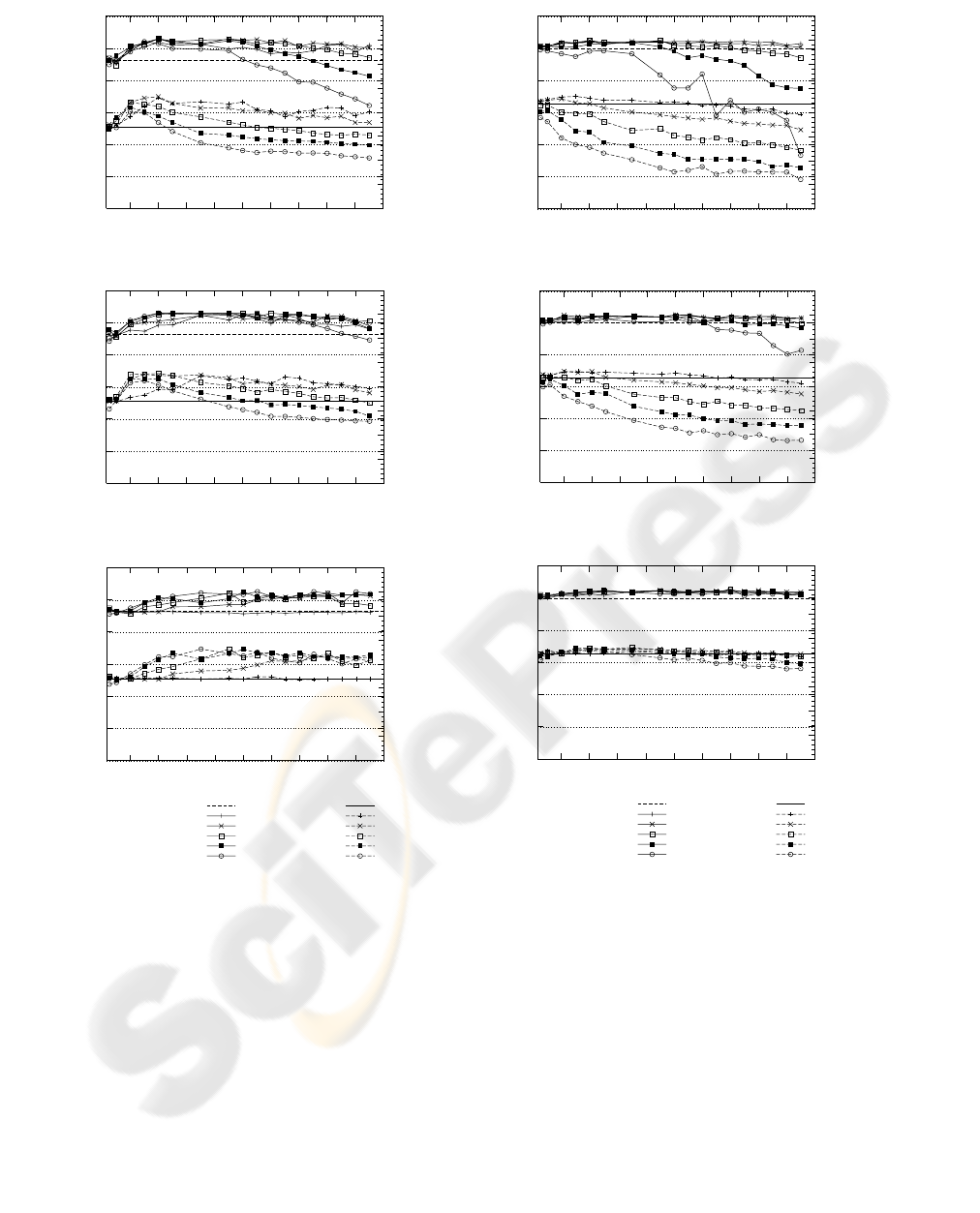
achieving low packet latency. Fig. 7 shows the
average goodput and delay of some selected results
(
α
= 0.5,
α
= 1,
α
= 5), considering a single TCP
flow over the RLC layer.
Fig. 8 shows the same measures in a scenario
with four TCP flows. In these figures, the goodput
and delay performance for the conventional RLC
drop-tail (DT) operation is also shown as a reference
value.
It should be stated that our objective is to
improve the goodput while reducing the delay,
which, as can be seen on first inspection of figures 7
and 8, is achieved for the single-flow scenario in
many configurations. In the multiple-flow scenario,
the goodput improvement is negligible but the delay
reduction is up to 50%.
The aggressiveness of the algorithm is
determined by the combined values of minth, maxd
and
α
. Given a certain BO value, the algorithm is
more aggressive if the ACK rate reduction is higher
(higher t
id
). For an optimum performance, the
relation between BO and t
id
should balance two
opposed objectives: avoiding overbuffering and
achieving full use of the radio bearer bandwidth.
Figures 7 and 8 show that the aggressiveness
increases for lower values of minth and
α
, and for
higher values of maxth. As expected, if the
configuration is too aggressive, the goodput decays.
Wireless
Channel
RLC
Frame Error Rate: 10%
RTT: 50 ms, Nominal Rate: 384 kbit/s
Networ
k
Side
User
Side
RLC
T
C
P sources
#1
TCP receivers
#3
#2
#4
#1 #3
#2
#4
RTT Internet: 200 ms
minth
Downlink
buffer
Uplink
buffer
(reverse
ACK flow)
A
rtificial
delay
Figure 6: Simulator topology.
WINSYS 2006 - INTERNATIONAL CONFERENCE ON WIRELESS INFORMATION NETWORKS AND SYSTEMS
38
In most TCP implementations, one ACK packet
is sent when two TCP segments are received in
sequence. In our environment it implies that, in
normal operation, two consecutive ACKs are spaced
approximately 140 ms. Therefore, if t
id
is around this
value, the effect of the algorithm is imperceptible,
and if t
id
reaches e.g. 240 ms, the ACK rate (and thus
the source’s rate) is halved. Our simulations show
that optimum configurations follow roughly a
similar pattern: t
id
is lower than 240 ms for BO
values below 10 SDUs, and for BO values around 20
SDUs, the rate is divided by 3.
Table 2 shows the performance figures of four
possible optimum configurations, contrasted with
that of RLC without ACK rate control algorithm.
Fig. 9 shows the shape of the function t
id
= f(BO) for
these configurations. It can be seen that the rate
reduction is similar for certain BO levels, as stated
before.
It is clear that optimum configurations require
α
< 1. The effect of
α
is shown in Fig. 10 (single
flow) where minth = 10. The performance is worse
for
α
> 1 because the rate reduction is concentrated
on higher BO values (see Fig. 5). The algorithm
tends to react only when the congestion is too high,
50
100
150
200
250
300
350
200 400 600 800 1000 1200 1400 1600 1800 2000
0
0.25
0.5
0.75
1
1.25
1.5
1.75
2
Goodput (Kbit/s)
End-to-end delay (s)
maxd
Figure 7 (a): α = 0.5
50
100
150
200
250
300
350
200 400 600 800 1000 1200 1400 1600 1800 2000
0
0.25
0.5
0.75
1
1.25
1.5
1.75
2
Goodput (Kbit/s)
End-to-end delay (s)
maxd
Figure 7 (b): α = 1
50
100
150
200
250
300
350
200 400 600 800 1000 1200 1400 1600 1800 2000
0
0.25
0.5
0.75
1
1.25
1.5
1.75
2
Goodput (Kbit/s)
End-to-end delay (s)
maxd
DT
minth: 40
minth: 30
minth: 20
minth: 10
minth: 0
delay DT
delay minth: 40
delay minth: 30
delay minth: 20
delay minth: 10
delay minth: 0
Figure 7 (c). α = 5
50
100
150
200
250
300
350
200 400 600 800 1000 1200 1400 1600 1800 2000
0
0.25
0.5
0.75
1
1.25
1.5
1.75
2
Goodput (Kbit/s)
End-to-end delay (s)
maxd
Figure 8 (a): α = 0.5
50
100
150
200
250
300
350
200 400 600 800 1000 1200 1400 1600 1800 2000
0
0.25
0.5
0.75
1
1.25
1.5
1.75
2
Goodput (Kbit/s)
End-to-end delay (s)
maxd
Figure 8 (b): α = 1
50
100
150
200
250
300
350
200 400 600 800 1000 1200 1400 1600 1800 2000
0
0.25
0.5
0.75
1
1.25
1.5
1.75
2
Goodput (Kbit/s)
End-to-end delay (s)
maxd
DT
minth: 40
minth: 30
minth: 20
minth: 10
minth: 0
delay DT
delay minth: 40
delay minth: 30
delay minth: 20
delay minth: 10
delay minth: 0
Figure 8 (c). α = 5
Figure 7: Performance of the single-flow scenario. Figure 8: Performance of the 4-flows scenario
ACK RATE CONTROL STRATEGY AT THE LINK LAYER TO ENHANCE TCP OVER 3G LINKS
39
which is less effective preventing buffer overflow.
In fact, for
α
>> 1, the algorithm effect vanishes
(t
id
= 0).
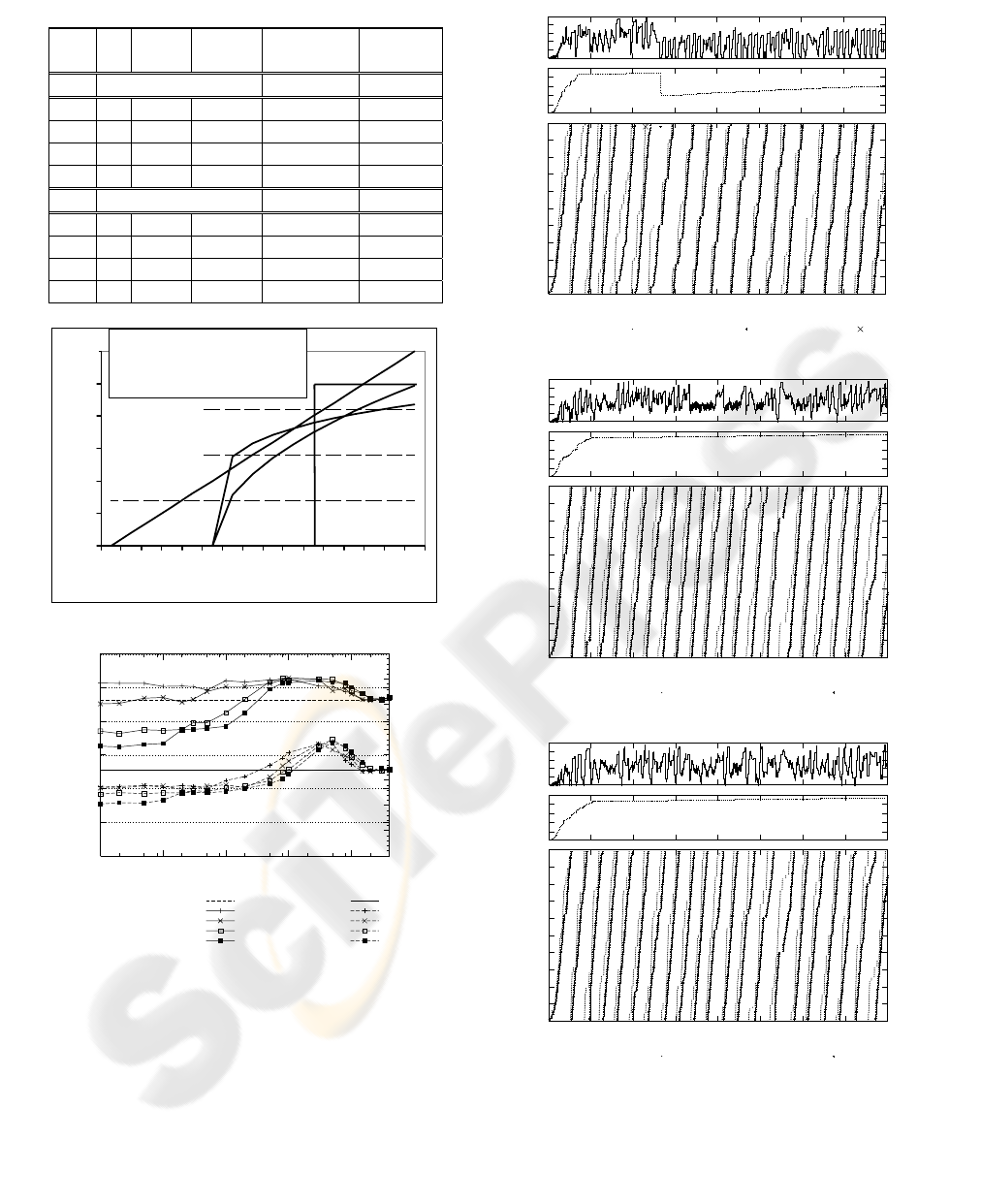
Finally, Fig. 11 shows traces of three of the
selected configurations (
α
= 0,
α
= 0.2 and
α
= 1).
The traces provide further insight on the algorithm
performance. In general, buffer overflow is avoided,
and the overall behaviour is better than that shown in
Fig. 2. For
α
= 0.2, we can see a single packet loss,
because minth is higher in this scenario. The
α
= 0
and
α
= 1 cases show a noticeable oscillation in the
buffer occupancy process. For
α
= 0 it is caused by
the abrupt increment on t
id
. For
α
= 1, the increment
0
10
20
30
40
50
60
70
80
90
100
0 10
20 30 40 50 60 70 80
Sequence Number
Time (s)
data sent data rx drop
10
20
30
40
50
cwnd
0
10
20
30
40
50
BO
(a):
α
= 0, maxd = 0.5 s, minth = 20
0
10
20
30
40
50
60
70
80
90
100
0 10 20 30 40 50 60 70 80
Sequence Number
Time (s)
data sent data rx
10
20
30
40
50
cwnd
0
10
20
30
40
50
BO
(b):
α
= 0.2, maxd = 0.5 s, minth = 10
0
10
20
30
40
50
60
70
80
90
100
0 10 20 30 40 50 60 70 80
Sequence Number
Time (s)
data sent data rx
10
20
30
40
50
cwnd
0
10
20
30
40
50
BO
(c):
α
= 1, maxd = 1 s, minth = 0
Figure 11: TCP traces with ACK rate control.
Table 2: Performance Figures.
TCP
flows
α minth
(SDUs)
maxd
(ms)
Goodput
(kbit/s)
Delay
(s)
1 Conventional RLC 281.9 ± 8.9 0.85±0.05
1 0 20 500 310.4±5.9 0.84±0.02
1 0.2 10 500 308.2 ± 6.2 0.78±0.03
1 0.5 10 700 305.9±5.6 0.78±0.03
1 1 0 1000 311.2±2.5 0.76±0.01
4 Conventional RLC 299.9 ± 3.9 1.09±0.02
4 0 20 500 302.7±7.9 0.72±0.02
4 0.2 10 500 301.4. ± 7.9 0.59±0.03
4 0.5 10 700 309±5.6 0.65±0.02
4 1 0 1000 306.3±6.9 0.56±0.03
Figure 9: f(BO) of the selected configurations.
50
100
150
200
250
300
350
0.001 0.01 0.1 1 10
0
0.25
0.5
0.75
1
1.25
1.5
1.75
2
Goodput (Kbit/s)
End-to-end delay (s)
α
DT
maxd: 500
maxd: 700
maxd: 1000
maxd: 1200
delay DT
delay maxd: 500
delay maxd: 700
delay maxd: 1000
delay maxd: 1200
Figure 10: Effect of α. Single-flow scenario.
0
0,1
0,2
0,3
0,4
0,5
0,6
0 2 4 6 8 1012141618202224262830
B
O
(SDUs)
(4)
(3)
(2)
(1)
nominal rate
nominal rate / 2
nominal rate / 3
(1)
α
= 0, maxd = 0.5 s, minth = 20
(2)
α
= 0.2, maxd = 0.5 s, minth = 10
(3)
α
= 0.5, maxd = 0.7 s, minth = 10
(4)
α
= 1, maxd = 1 s, minth = 0
)(st
id
WINSYS 2006 - INTERNATIONAL CONFERENCE ON WIRELESS INFORMATION NETWORKS AND SYSTEMS
40

is gradual but relatively slow given the transmission
delay of the control loop. The source reacts “a bit
late” and “a bit too stark” causing an apparent
instability. The stability of the algorithm from a
control system point of view is an issue for further
research. For 0 <
α
< 1, the algorithm shows lower
BO oscillations, which justifies the generalized
delay computation approach proposed in this paper.
6 CONCLUSIONS
Our proposed ACK rate control algorithm improves
end-to-end goodput and delay performance when
RLC supports a single or multiple TCP flows. The
algorithm performs equally well in the slow start and
in the congestion avoidance phase of TCP
connections. In contrast to similar proposals done in
the field of satellite links, we consider a more
general way of calculating the inter-departure time
of ACKs. Moreover, we provide a detailed algorithm
that clarifies the operation and the implementation.
By means of extensive simulation tests we
provide insight about the influence of each
parameter, which let us find multiple possible
configurations improving overall performance. The
key issue in selecting an accurate parameter setting
is to tune the rate reduction of the algorithm
according to the congestion level of the link,
reflected in the buffer occupancy. Configurations
showing similar performance figures (goodput and
delay) presented a similar ACK rate reduction
pattern for low and high BO levels. However, it was
found that the value of
α
has a noticeable impact on
the oscillatory behavior of the BO process.
An important advantage of our algorithm
compared to random or RED-like mechanisms is its
deterministic operation, which reduces the
computational cost of the algorithm, and makes it
more feasible for its implementation at the RLC
level where the buffering is done in a per-user basis.
Some additional advantages of our algorithm are
that it does not require changes in 3G specifications
nor in TCP itself, and preserves TCP end-to-end
semantics.
REFERENCES
3GPP, 2005. “Radio Link Control (RLC) protocol
specification”, v. 6.4.0., TS 25.322.
H. Inamura et al., 2003. “TCP over Second (2.5G) and
Third (3G) Generation Wireless Networks” IETF RFC
3481.
J. J. Alcaraz, F. Cerdan and J. García-Haro, 2006.
“Optimizing TCP and RLC Interaction in the UMTS
Radio Access Network”, IEEE Network, vol 20, no.
2, pp. 56 - 64.
Jing Wu et al., 1999. “ACK Delay Control for Improving
TCP Throughput over Satellite Links”, Proc. IEEE
ICON’99, pp. 303- 312.
M. Rossi, L. Scaranari and M. Zorzi, 2003, “On the
UMTS RLC Parameters Setting and their Impact on
Higher Layers Performance”, in Proc. IEEE 57th VTC,
vol. 3, pp. 1827- 32.
R. Chakravorty, A. Clark and I. Pratt, 2005. “Optimizing
Web Delivery over Wireless Links: Design,
Implementation and Experiencies”, IEEE J. Select.
Areas Commun., vol. 23, no. 2, pp. 402- 416.
A. Gurtov, S. Floyd, 2004. “Modeling Wireless Links for
Transport Protocols”, ACM SIGCOMM Computer
Communication Review, vol. 34, no. 2, pp. 85-96.
R. Bestak, P. Godlewski and P. Martins, 2002. “RLC
Buffer Occupancy when Using a TCP Connection
over UMTS”, in Proc. IEEE PIMRC’02, vol. 3. pp.
1161-65.
A. Varga, 2001. “The OMNeT++ Discrete Event
Simulation System”, in Proc. European Simulation
Multiconference.
H. Holma, A. Toskala, 2004. WCDMA for UMTS: Radio
Access for Third Generation Mobile Communications,
Third Edition, Wiley.
A. Chockalingam and M. Zorzi, 1999. “Wireless TCP
Performance with Link Layer FEC/ARQ”, in Proc.
IEEE ICC’99, pp. 1212-16.
M. Meyer, J. Sachs and M. Holzke, 2003. “Performance
Evaluation of a TCP Proxy in WCDMA Networks”,
IEEE Wireless Communication, pp.70-79.
ACK RATE CONTROL STRATEGY AT THE LINK LAYER TO ENHANCE TCP OVER 3G LINKS
41
