
A NOVEL APPROACH TO PLANAR CAMERA CALIBRATION
Ashutosh Morde, Mourad Bouzit, Lawrence Rabiner
CAIP, Rutgers University
96 Frelinghuysen Road, Piscataway, NJ 08855
Keywords:
Camera Calibration, Image of Absolute Conic, Vanishing Line, Concentric Circles.
Abstract:
Camera calibration is an important step in 3D reconstruction of scenes. Many natural and man made objects
are circular and form good candidates as calibration objects. We present a linear calibration algorithm to
estimate the intrinsic camera parameters using at least three images of concentric circles of unknown radii.
Novel methods to determine the projected center of concentric circles of unknown radii using the projective
invariant, cross ratio, and calculating the vanishing line of the circle are proposed.
The circular calibration pattern can be easily and accurately created. The calibration algorithm does not require
any measurements of the scene or the homography between the images. Once the camera is fully calibrated
the focal length of zooming cameras can be estimated from a single image. The algorithm was tested with real
and synthetic images with different noise levels.
1 INTRODUCTION
Camera calibration is an essential step in many com-
puter vision and photogrammetric applications. It
consists of recovering the metric properties which are
encoded as a set of so-called internal parameters. It
has been a subject of active research with numer-
ous methods (Tsai, 1987; Strum and Maybank, 1999;
Zhang, 2000). Once the cameras are calibrated, the
projective relationship from 3D space to 2D image
can be established.
The existing camera calibration techniques can be
broadly classified as linear, (Grosky and Tamburino,
1990; Strum and Maybank, 1999), and non-linear
(Heikkila, 2000; Meng and Hu, 2003). The non linear
techniques have the disadvantage of requiring good
initial estimates of the intrinsic parameters and being
computationally intensive. If the starting point of the
algorithm is not well chosen the solution can diverge
or can get trapped in a local minimum. A linear ap-
proach is not plagued with these problems.
Camera calibration can also be broadly classified
based on the type of calibration object, viz. 3D cali-
bration object, and 2D calibration object. Most com-
monly used calibration procedures described in the
computer vision literature rely on a calibration object
with control points whose 3D coordinates are known
with a high degree of accuracy to obtain accurate re-
sults (Tsai, 1987; Heikkila, 2000). As compared to
a 3D calibration object, 2D calibration patterns offer
the advantage of easily creating an accurate calibra-
tion object; the calibration pattern can be printed on
a laser printer and mounted on a flat surface. Tech-
niques utilizing planar patterns require multiple views
of the calibration object (Strum and Maybank, 1999;
Zhang, 2000). The camera motion between the im-
ages need not be known.
Conics can be used instead of control points as it
is easy to match correspondences. They project onto
the image plane as ellipses from any view and have
been widely used before to estimate the camera pose
(Kanatani and Liu, 1993; Chen and Huang, 1999).
The use of circles and ellipses as 2D calibration ob-
jects have been increasing. There are various non-
linear planar calibration algorithms which use circles
and ellipses of known dimension as calibration object
(Yang et al., 2000; Kim and Kweon, 2001; Kim et al.,
2002; Abad et al., 2004).
We propose a novel linear method, which exploits
the Thales theorem for circles, to calculate the van-
ishing line of the circle and the corresponding Image
of the Circular Points (ICP’s). The camera intrinsic
parameters are then determined, from at least 3 im-
ages, using the Image of Absolute Conic (IAC) as
87
Morde A., Bouzit M. and Rabiner L. (2006).
A NOVEL APPROACH TO PLANAR CAMERA CALIBRATION.
In Proceedings of the First International Conference on Computer Vision Theory and Applications, pages 87-92
DOI: 10.5220/0001362500870092
Copyright
c
SciTePress
the calibration object. The projected center of con-
centric circles required by the calibration algorithm
is accurately determined using the cross ratio with-
out any knowledge of the circle radii. The calibration
method has the advantage of not requiring any metric
measurements nor any correspondences between the
images.
The paper is organized as follows. In section 2 we
describe the theory used; in section 3 we present novel
algorithms to find the projected center of concentric
circles and the vanishing line of the circle. In section
4 we discuss the camera calibration algorithm and the
results, which is followed by the conclusion.
2 THEORY
We adopt a perspective camera model with intrinsic
matrix K,
K =
f
u
su
0
0 f
v
v
0
001
. (1)
where f
u
and f
v
are the effective camera focal lengths
along the camera axes u and v, s is the skew of the
CCD plane and (u
0
,v
0
) is the coordinate of the image
center. A homogeneous point
˜
X =[X, Y, Z, 1] gets
projected to ˜x =[u, v, w] as
λ˜x = K [RT]
˜
X
i.e. λ˜x = KM
ext
˜
X = M
˜
X
. (2)
where M
ext
is the camera extrinsic parameter matrix
with R and T , the rotation matrix and the translation
vector from the world to the camera system respec-
tively and λ is a non zero scale factor.
Let a circle with radius R
c
and center at [X
c
,Y
c
, 0]
lie in the z plane of the world coordinate system. A
homogeneous point [X, Y, 1] on the circle satisfies the
equation
[XY 1]
⎡
⎣
10 −X
c
01 −Y
c
−X
c
−Y
c
X
2
c
+ Y
2
c
− R
2
c
⎤
⎦
X
Y
1
=0
i.e. X
T
CX =0
. (3)
This circle gets projected as the ellipse X
T
AX =
0, where A is the matrix defining the ellipse and is
related to the circle up to a scale factor λ by
λA = H
−T
CH
−1
. (4)
where H = K [
R
1
R
2
T
]=KM
h
is the ho-
mography transforming the circle into an ellipse; R
1
and R
2
are the first and second columns of the rota-
tion matrix R.
All circles pass through the circular points I =
(1,i,0)
T
and J =(1, −i, 0)
T
whose position is in-
variant to plane similarity transformation. A special
circle is the absolute conic which is an imaginary cir-
cle located in the plane at infinity and is also invariant
to similarity transformations. All circles intersect the
absolute conic and the line at infinity at the circular
points (Hartley and Zisserman, 2000). The absolute
conic, C
∞
= I, forms a natural calibration object
with the IAC, ω, being related to the intrinsic matrix
under the homography H
∞
= KM
h
∞
by
ω = H
−T
∞
C
∞
H
−1
∞
=(KM
h
∞
)
−T
I (KM
h
∞
)
−1
= K
−T
M
−T
h
∞
M
−1
h
∞
K
−1
= K
−T
K
−1
.
(5)
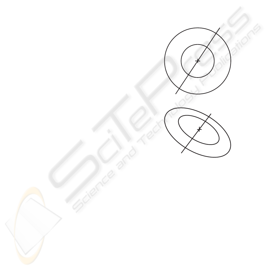
P
2
P
C
P
3
P
4
P
1
(a)
P
1
P
2
P
C
P
3
P
4
(b)
Figure 1: Projection of concentric circles.
3 FROM CIRCLES TO
RECTANGLES
3.1 Projected Center of Circle
A 3D circle gets projected as an ellipse from any view
but the projected center of the 3D circle does not co-
incide with the center of the ellipse (J.L.Mundy and
A.Zisserman, 1992). The projected center of concen-
tric circles lies on the line joining the centers of the
projected ellipses (Kim and Kweon, 2001) and it can
be determined by using the projective invariant, cross
ratio. The cross ratio of four points (P
1
,P
2
,P
3
,P
4
)
is defined as
VISAPP 2006 - IMAGE FORMATION AND PROCESSING
88
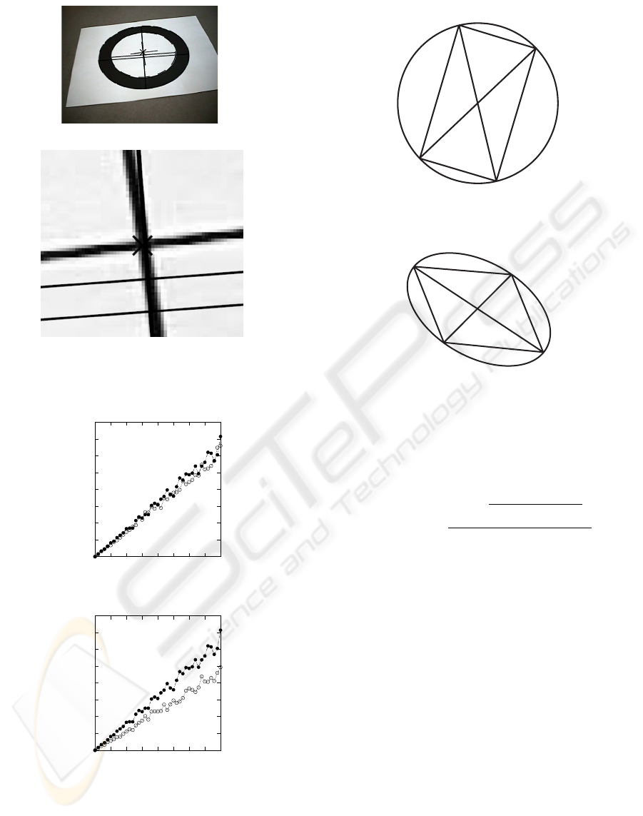
(a)
(b)
Figure 2: Projected center of circle.
0
0.05
0.1
0.15
0.2
0.25
0.3
0.35
0.4
0 0.5 1 1.5 2 2.5 3 3.5 4
Mean Error
Noise in pixels
(a) Projected circle center error
0
0.05
0.1
0.15
0.2
0.25
0.3
0.35
0.4
0 0.5 1 1.5 2 2.5 3 3.5 4
Std. Dev.
Noise in pixels
(b) Std. Dev. of projected circle
center
Figure 3: Influence of noise on finding projected center of
circle.
P
1
P
2
P
C
P
3
P
4
(a) Rectangle inscribed by two
diameters
P
4
P
3
P
C
P
2
P
1
(b) Its projection
Figure 4: Rectangle inscribed in a circle.
CR(P
1
,P
2
,P
3
,P
4
)=
d(P
1
,P
2
)∗d(P
3
,P
4
)
d(P
1
,P
3
)∗d(P
2
,P
4
)
. (6)
where d (j, k)=
(x
j
− x
k
)
2
+(y
j
− y
k
)
2
is the
distance between points j and k. With three fixed
points the cross ratio is a monotonic function of the
fourth point. As any one point is made to move
along the line joining all the points the cross ratio in-
creases/decreases. For example, in figure 1, moving
point P
3
closer to point P
4
causes the cross ratio to
decrease while moving point P
3
away from point P
4
causes the cross ratio to increase.
Consider four points lying on the diameter of two
concentric circles with center P
C
as shown in figure
1(a). For these four points we have
CR(P
1
,P
2
,P
C
,P
3
)=CR(P
4
,P
3
,P
C
,P
2
) . (7)
As the cross ratio is a projective invariant the same
is true for figure 1(b) which is a projection of the con-
centric circles in figure 1(a). The algorithm for find-
ing the circle center then involves :
1. Initializing the projected circle center as the inner
ellipse center
2. A binary search along the line joining the two el-
lipse centers bounded by points P
2
and P
3
A NOVEL APPROACH TO PLANAR CAMERA CALIBRATION
89
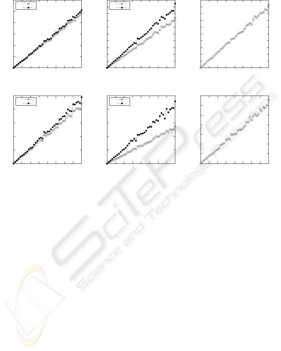
0
5
10
15
20
25
30
0 0.5 1 1.5 2 2.5 3 3.5 4
Mean Error
Noise in pixels
fu
fv
(a) Mean error for f
u
and f
v
0
2
4
6
8
10
12
14
16
18
20
0 0.5 1 1.5 2 2.5 3 3.5 4
Mean Error
Noise in pixels
u0
v0
(b) Mean error for u
0
and v
0
0
1
2
3
4
5
6
7
8
9
10
0 0.5 1 1.5 2 2.5 3 3.5 4
Mean Error
Noise in pixels
(c) Mean error for skew
0
5
10
15
20
25
0 0.5 1 1.5 2 2.5 3 3.5 4
Std. Dev.
Noise in pixels
fu
fv
(d) Std. Dev. of f
u
and f
v
0
5
10
15
20
25
0 0.5 1 1.5 2 2.5 3 3.5 4
Std. Dev.
Noise in pixels
u0
v0
(e) Std. Dev. of u
0
and v
0
0
2
4
6
8
10
12
14
0 0.5 1 1.5 2 2.5 3 3.5 4
Std. Dev.
Noise in pixels
(f) Std. Dev of skew
Figure 5: Influence of noise in calculating intrinsic parameters.
(a) If CR(P
1
,P
2
,P
C
,P
3
) >CR(P
4
,P
3
,P
C
,P
2
)
then move P
C
towards point P
3
(b) If CR(P
1
,P
2
,P
C
,P
3
) <CR(P
4
,P
3
,P
C
,P
2
)
then move P
C
towards point P
2
Due to the monotonic nature of the cross ratio the
algorithm always converges, usually in 2-3 iterations.
In figure 2 the circle center was correctly calculated as
(333.86, 190.76) for a real image. Figure 3 shows the
result of a simulation of finding the projected center
of circle; the simulation parameter details are given
in section 4.2 along with the calibration results . The
algorithm is observed to be very robust to noise per-
turbations and correctly calculates the projected circle
center while the ellipse centers do not coincide with
the projected circle center.
3.2 Vanishing Line of a Circle
The vanishing line is the image of the line at infinity
and its intersection with the image of a circle gives
the image of circular points. Any two lines through a
circle center form the diagonals of a rectangle. Figure
4 illustrates this with lines P
1
P
C
P
3
and P
2
P
C
P
4
be-
ing the diameters of the circle and inscribing a rectan-
gle P
1
P
2
P
3
P
4
. The procedure for finding the vanish-
ing line starts off with intersecting two lines passing
through the projected center of circle with an ellipse,
the image of the circle. This gives a quadrilateral
P
1
P
2
P
3
P
4
, figure 4(b), which is the image of a rec-
tangle. Thus intersecting lines P
1
P
2
and P
4
P
3
gives
one vanishing point while intersecting lines P
1
P
4
and
P
2
P
3
gives another vanishing point. The two van-
ishing points are then used to compute the vanishing
line.
4 CAMERA CALIBRATION
4.1 Calibration Algorithm
The procedure for calibrating the camera involves the
following steps :
• Capture 3 views of the concentric circles and for
each image
– fit ellipses using the direct least squares method
(Fitzgibbon et al., 1999)
VISAPP 2006 - IMAGE FORMATION AND PROCESSING
90
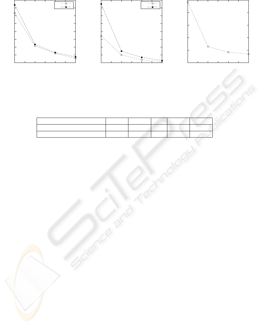
2
2.5
3
3.5
4
4.5
5
5.5
6
3 3.5 4 4.5 5 5.5 6
Std. Dev.
Number of images
fu
fv
(a) Std. Dev. of f
u
and f
v
1.5
2
2.5
3
3.5
4
4.5
5
5.5
3 3.5 4 4.5 5 5.5 6
Std. Dev.
Number of images
u0
v0
(b) Std. Dev. of u
0
and v
0
0.5
1
1.5
2
2.5
3
3 3.5 4 4.5 5 5.5 6
Std. Dev.
Number of images
(c) Std. Dev of skew
Figure 6: Effect of increasing the number of images on calculating intrinsic parameters.
Table 1: Comparison of Calibration results.
f
u
f
v
s u
0
v
0
Proposed Algorithm 812.03 810.31 -0.6 314.25 239.47
Zhang’s Planar Calibration 788.83 789.27 0 318.73 241.13
– Calculate the projected center of the circles as
described in section 3.1
– Estimate the vanishing line as explained in sec-
tion 3.2
– Intersect the vanishing line with an ellipse to get
the two ICP’s.
• Fit an ellipse to the 6 ICPs to obtain the Image of
IAC
• Perform Cholesky Decomposition of the IAC ma-
trix to obtain the camera intrinsic parameters
Once the camera is calibrated the ICP’s from a sin-
gle image can be used to estimate the focal length of
zooming cameras (Strum and Maybank, 1999).
4.2 Calibration Result
The accuracy of the proposed algorithm was tested
using simulations. The simulations were performed
with circles of radii 120mm and 60mm with 400
points per circle and a camera with intrinsic matrix
K =
845.79 0.1 315.24
0 875.46 226.13
001
. (8)
The camera was setup in 6 different locations with
the projection of the larger circle varying as an ellipse
with half major axis length of 130-190 pixels and the
half minor axis length of 80-150 pixels. For trials with
less than 6 images, all possible camera pose combina-
tions were used. Thus when calibrating using just 3
images, the 6 camera poses provide
6
3
= 120 sets to
work with. The projected circle points were perturbed
with zero mean gaussian noise while the standard de-
viation was varied from 0 to 4 pixels. Figure 5 shows
the accuracy of the technique in estimating the intrin-
sic parameters at various noise levels for 200 indepen-
dent trials. The estimation error is found to be small
and its standard deviation increases with the noise lev-
els. In figure 6 we observe that the standard deviation
of the estimated intrinsic parameters decreases with
the increase in the number of images used for calibra-
tion.
The algorithm was also tested with real images
of dimension 640 by 480 taken by a Sony Lipstick
camera. Table 1 gives the results of camera calibra-
tion with the proposed algorithm and Zhang’s (Zhang,
2000) method. The results are comparable, the dif-
ference could be accounted by the use of non linear
minimization and estimation of distortion coefficients
in (Zhang, 2000).
5 CONCLUSION
We proposed a novel camera calibration method us-
ing concentric circles. An algorithm for estimat-
ing the projected center of concentric circles with-
out using any radii information was developed. A
method for finding the vanishing line of a circle and
the corresponding ICP’s was proposed. The calibra-
tion process does not require any measurements of the
planar pattern; thus any natural pattern of concentric
A NOVEL APPROACH TO PLANAR CAMERA CALIBRATION
91

circles can also be used as a calibration object. Ex-
periments with simulated data as well as real images
showed the insensitivity of the algorithm to varying
levels of noise. The estimated intrinsic parameters
had low mean errors and standard deviation. Increas-
ing the number of images beyond the minimum value
of 3 resulted in a decrease in standard deviation of the
errors.
REFERENCES
Abad, F., Camahort, E., and Vivo, R. (2004). Camera cali-
bration using two concentric circles. In International
Conference on Image Analysis and Recognition, vol-
ume 3211, pages 688–696.
Chen, Z. and Huang, J. (1999). A vision-based method for
the circle pose determination with a direct geometric
interpretation. In IEEE Transactions on Robotics &
Automation, volume 15, pages 1135–1140.
Fitzgibbon, A., Pilu, M., and Fisher, R. B. (1999). Di-
rect least square fitting of ellipses. In IEEE Trans-
actions on Pattern Analysis & Machine Intelligence,
volume 21.
Grosky, W. and Tamburino, L. (1990). A unified approach
to the linear camera calibration problem. IEEE Trans-
actions on Pattern Analysis and Machine Intelligence,
12:663–667.
Hartley, R. and Zisserman, A. (2000). Multiple View Geom-
etry in Computer Vision. Cambridge University Press.
Heikkila, J. (2000). Geometric camera calibration using cir-
cular control points. IEEE Transactions on Pattern
Analysis and Machine Intelligence, 22:1066–1077.
J.L.Mundy and A.Zisserman, editors (1992). Geometric In-
variance in Computer Vision. MIT Press.
Kanatani, K. and Liu, W. (1993). 3d interpretation of con-
ics and orthogonality. CVGIP: Image Understanding,
58:286–301.
Kim, J. S., Kim, H. W., and Kweon, I. S. (2002). A camera
calibration method using concentric circles for vision
applications. In Asian Conference on Computer Vi-
sion, volume 2, pages 515–520.
Kim, J. S. and Kweon, I. S. (2001). A new camera calibra-
tion method for robotic applications. In International
Conference on Intelligent Robots and Systems, pages
778–783.
Meng, X. and Hu, Z. (2003). A new easy camera calibration
technique based on circular points. Pattern Recogni-
tion, 36:1155–1164.
Strum, P. and Maybank, S. (1999). On plane based camera
calibration: A general algorithm, singularities, appli-
cations. In Computer Vision and Pattern Recognition,
pages 432–437.
Tsai, R. Y. (1987). A versatile camera calibration technique
for high-accuracy 3d machine vision metrology using
off-the-shelf tv cameras and lenses. IEEE Journal of
Robotics and Automation, 3:323–344.
Yang, C., Sun, F., and Hu, Z. (2000). Planar conic based
camera calibration. In International Conference on
Pattern Recognition, volume 1, pages 1555–1558.
Zhang, Z. (2000). A flexible new technique for camera cal-
ibration. IEEE Transactions on Pattern Analysis and
Machine Intelligence, 22:1330–1334.
VISAPP 2006 - IMAGE FORMATION AND PROCESSING
92
