
DISCRETE TOOLS FOR VIRTUAL SCULPTURE
Xavier Heurtebise, Sébastien Thon
LSIS, Marseille, France
Keywords: Geometry and modelling, virtual sculpture, voxels, levels of detail, 3D wavelets.
Abstract: In a virtual sculpture project, we represent the material to be sculpted as a set of volume elements (voxels).
Sculpture operations of subtraction and addition are applied on these voxels with tools with various shapes
and sizes. A major advantage of our system is that sculpted objects can then be used as new tools, because
the same model is used for both objects and tools. This is a multiresolution model based on a 3D wavelet
transform. We take advantage of the levels of detail to speed up display and sculpture. However, using
discrete models for objects and tools leads to three problems: important computation time, aliasing when
tools are rotated, and how to perform sculpture operations between discrete objects and tools with different
orientations and sizes. In this paper, we describe our model and then propose solutions to these problems
that allow real-time performance.
1 INTRODUCTION
1.1 Presentation
We present in this paper a multiresolution model
based on 3D wavelets to represent a 3D objects as a
discrete set of volume elements (voxels). Such a
discrete representation is of great use in a virtual
sculpture context as it allows to simulate easily
sculpture operations such as subtraction or addition
of material by simply adding or removing voxels. A
great improvement of our model is its
multiresolution nature given by the use of wavelets,
that allows to accelerate display, interaction and
sculpture operations by the use of levels of detail.
Another major advantage of our system is that we
use this model to represent both objects and tools, so
we can let the user design his or her own tools, by
sculpting them from basic objects. This is an original
approach to virtual sculpture, where most of other
approaches use different models for objects and
tools. However, if other approaches generally use
implicit tools (such as ellipsoids), it is because the
use of discrete tools is a difficult topic, due to three
problems:
− First, this is computationally expensive,
especially when the tool has to be rotated in its
discrete grid of voxels when the tool orientation
is changed.
− Second, there is a degradation of the shape of
the tool due to aliasing if angles of rotation are
not multiple of 90 degrees.
− Third, it is unclear how to perform sculpture
operations such as subtraction or addition
between discrete objects and tools with different
orientations and sizes.
1.2 Previous Works
In this paper, we tackle the problem of virtual
sculpture of 3D objects with tools, both represented
with spatial enumerations. Such a spatial
enumeration is a set of volume elements called
voxels, obtained by sampling the volume of a 3D
object. It can be seen as a 3D image composed of
voxels, where a 2D image is an array composed of
pixels. To make a spatial enumeration from a 3D
object, several methods have already been
suggested. The simplest way is a uniform spatial
enumeration, by regularly sampling the 3D object
into voxels with the same size. However, a major
drawback of this representation is the large number
of voxels needed to represent large objects with
detailed features. This entails three main problems.
The first one is the important memory cost to store
this uniform spatial enumeration. The second one is
that the display of these objects becomes slower.
Finally, operations on these objects such as sculpture
actions or displacements become less and less
interactive.
415
Heurtebise X. and Thon S. (2006).
DISCRETE TOOLS FOR VIRTUAL SCULPTURE.
In Proceedings of the First International Conference on Computer Graphics Theory and Applications, pages 415-422
DOI: 10.5220/0001354604150422
Copyright
c
SciTePress

To prevent these inconveniences, adaptive
sampling methods have been developed. Libes
(Libes, 1991) uses an octree to gather groups of
adjacent voxels having same values to reduce the
number of elements stored in memory. It’s very
simple to use and to implement this method. Ferley
(Ferley, 2002) also works on a n-tree where each
cell can be divided in 27 ones. This method looks
like an octree and allows to reach a high level of
detail. However, for an object with small details, the
subdivision level of an octree or n-tree will be very
high. So the processes (construction and use) will be
slow.
Several other sampling methods used in collision
detection propose to modify properties of the voxels,
such as the size, the orientation or even the shape.
With the AABB method (Axis Aligned
Bounding Boxes), Bergen (Bergen, 1997) suggests
to use voxels with different sizes. Gottschalk
(Gottschalk, 1996) proposes to modify not only the
size of the voxels but also their orientation, with the
OBB method (Oriented Bounding Boxes). Thanks to
these two methods, the object rendering is optimized
because the original object shape can be approached
with less voxels than with a simple uniform spatial
enumeration. The modeling is finer with OBB tree
than AABB tree for a same number of bounding
volumes. However, AABB tree uses less memory
storage than OBB tree for a same number of
bounding volumes. Indeed, an OBB is represented
by using 15 scalars (9 scalars for the orientation, 6
scalars for position and extent), whereas an AABB
only requires 6 scalars (for position and extent).
Moreover, to optimize the modeling of the 3D
object, these two methods suggest to reduce overlaps
between bounding boxes and to increase their filling
by the object, with the less possible boxes. This
optimization is expensive in processing time, so we
prefer using a uniform spatial enumeration or an
octree, because they are faster than AABB and OBB
methods.
Liu (Liu, 1988) and Hubbard (Hubbard, 1995)
propose to replace cubes by spheres in an octree to
form a spheres tree, because spheres accelerate
collision detection between objects. Later, Hubbard
(Hubbard, 1995) (Hubbard, 1996) and Bradshaw
(Bradshaw, 2004) suggest a finer modeling using
spheres tree thanks to an approximated medial-axis
of the 3D object, but this method is slower and more
complicated than an octree.
To further improve the use of spatial
enumeration, several methods of multiresolution
representations have been proposed. So, processing
and display times are adapted with the desired level
of detail. Among these methods, there are octree and
wavelet decomposition.
An octree can also be seen as a hierarchical
representation of 3D object. The maximum level of
subdivision of the octree defines the maximum level
of detail of a multiresolution representation. Boada
(Boada, 2001) defines a section in an octree that
determines the displayed nodes for a defined level of
detail. This method is extended to a n-tree by Ferley
(Ferley, 2002).
The second multiresolution method uses wavelet
decomposition. Wavelets are a mathematical tool for
representing functions hierarchically. In our case,
these functions are discrete 3D functions that define
a set of voxels. More information about wavelets
will be given in the section 2.1. Muraki (Muraki,
1992) (Muraki, 1993) shows the use of 3D Haar
wavelets to represent a 3D object. Pinnamaneni
(Pinnamaneni, 2002) builds a 3D Haar wavelet
decomposition from a sequence of 1D Haar wavelet
decomposition in each direction of the 3D voxels
grid. Wavelet decomposition allows to display a 3D
object faster according to the level of detail. It also
permits to drastically cut down the memory cost,
because high compression ratio can be achieved on
wavelets coefficients, especially if lossy
compression schemes are used.
The previously cited methods are about discrete
representation of 3D objects. Different methods have
already been proposed to sculpt these kinds of
objects.
Ayasse (Ayasse, 2001) performs sculpture
operations by the use of CSG (Constructive Solid
Geometry). Complex objects are created by
successive modifications of the material with a tool
according to simple operations such as difference,
union or intersection. However, the object and the
tool are represented by simple uniform spatial
enumerations. Moreover, voxels are limited to
binary values (full or empty). Ayasse proposes to
reduce the computation time for each sculpture
operation by using only the effective voxels of a
movement. This method can be useful because the
computation times are reduced. However, it doesn’t
use a multiresolution representation that could
improve the display performance or computation.
In the Kizamu project, Frisken (Frisken, 2001)
uses ADFs (Adaptively sampled Distance Fields) to
model and to sculpt the material. A 3D object is
sampled adaptively with a 3D grid according to the
details of the object. Each grid cell contains a scalar
specifying the minimum distance to the object
shape. This distance is signed to distinguish between
the inside and outside of the shape.
GRAPP 2006 - COMPUTER GRAPHICS THEORY AND APPLICATIONS
416

To represent an object to be sculpted, Ferley
(Ferley, 2002) also uses distance fields, stored in a
“n-tree” hierarchical representation where the
sampling rate depends on object’s details. The tool is
an ellipsoid defined by an implicit function that is
discretized to perform sculpture actions on the
object.
Bærentzen (Bærentzen, 2002) proposes the
Level-Set method to deform the material. This
method stores distance fields around the exterior of a
3D object. The tool is a blob represented by an
implicit function.
Raffin (Raffin, 2004) proposes a model of virtual
sculpture based on a multiresolution representation:
the octree. The tools are defined as voxels sets, but
they remain parallel to the axis.
1.3 Original Contribution
The main contribution of this paper is to propose a
discrete multiresolution model for virtual sculpture.
We take benefit of levels of detail to accelerate
display, interaction and sculpture operations. As the
same model is used to represent both objects and
tools, a major advantage of our system over existing
methods is that the user can create his or her own
tools from a previous sculpture. Furthermore, we
provide solutions to problems inherent to the use of
discrete objects, such as computation cost, aliasing
and operations between discrete tools and objects.
The remainder of the paper is organized as
follows: in section 2, we describe our discrete
multiresolution model. In section 3, we present the
tools, with original solutions for computation cost,
aliasing and sculpture operations. Then, we conclude
in section 4 and present future work in section 5.
2 OUR MODEL
In a virtual sculpture project, we represent the 3D
objects to be sculpted as a discrete set of voxels to
easily handle subtraction or addition of material by
tools. However, a uniform spatial enumeration is
expensive in processing and display times. Thus, we
propose a multiresolution model based on 3D Haar
wavelets.
2.1 About Wavelets
On the following example, we explain Haar wavelet
decomposition on a 1D case. First, consider a
sequence of p values, where p is a power of two
(here, p = 4 = 2
2
):
[
]
0
9, 7, 3, 5X =
Then, by applying Haar wavelet transform, we
can represent this sequence in terms of a low-
resolution sequence X
1
and a set of detail
coefficients Y
1
:
[]
1
9735
,8,4
22
X
++
==
⎡⎤
⎢⎥
⎣⎦
[]
1
9735
,1,1
22
Y
−−
=
=−
⎡⎤
⎢⎥
⎣⎦
So, by repeating these operations, we obtain
several sets of coefficients corresponding to
different levels of detail, as shown on the following
decomposition table:
level of detail
#
low-resolution
coefficients
detail
coefficients
0 [ 9 7 3 5 ]
1 [ 8 4 ] [ 1 -1 ]
2 [ 6 ] [ 2 ]
Thus, the higher the number of the level of
detail, the less detailed the sequence. The sequence
obtained by Haar wavelet decomposition has the
same size as the original sequence. Its coefficients
are the low-resolution coefficients of the last level of
detail and the different detail coefficients:
Original sequence: [ 9 7 3 5 ]
Final sequence: [6 2 1 -1]
The extraction of the original sequence from the
final sequence uses the inverse wavelet transform:
[
]
[
]
1
62,62 8,4X =+ −=
(
)()
[
]
[
]
0
81,81,4 1,4 1 9,7,3,5X =+ − +− −− =
2.2 Definition of our Model
Similarly, we can use this wavelet transform in a 3D
case. First, the 3D discrete object is defined by a
uniform spatial enumeration. Then, by using the
wavelet transform we build a hierarchical structure
that stores the coefficients of each level of detail of
this 3D object.
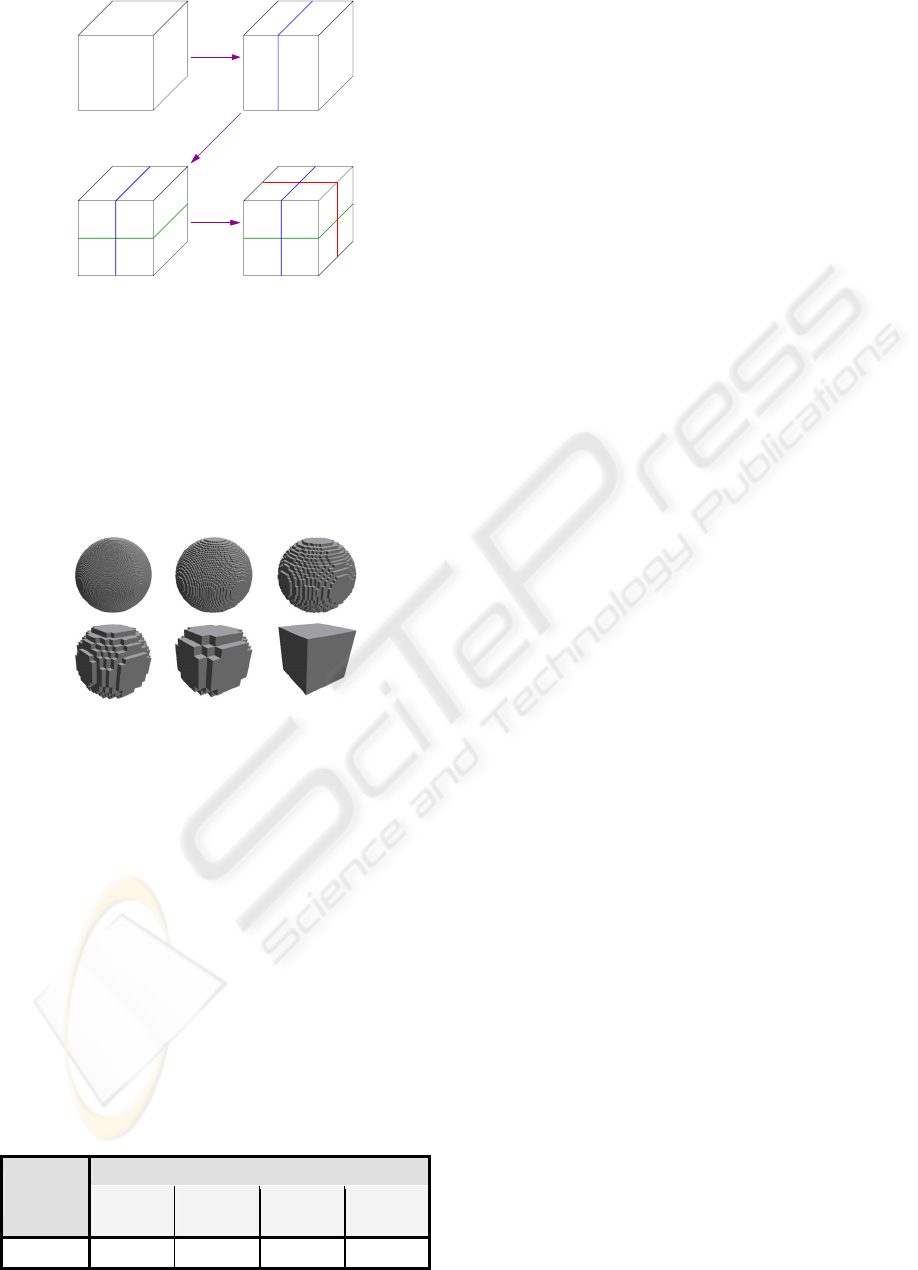
We use the hierarchical structure proposed by
Pinnamaneni [Pin02]. For each level of detail, the
1D Haar Wavelet transformation is applied in x-, y-
and z-direction successively (figure 1).
DISCRETE TOOLS FOR VIRTUAL SCULPTURE
417
LLH HLH
HHH
L
HHLH
HLLL
3D Image
H
LLL HLL
HHLLHL
Figure 1: 3D Haar wavelet decomposition.
For each transformation step, we obtain a bloc
‘L’ with low-resolution coefficients obtained by a
low-pass filter, and a bloc ‘H’ with detail
coefficients obtained by a high-pass filter.
The figure 2 shows a 3D Haar wavelet
decomposition for a sphere with 6 levels of detail.
Each voxel contains a density value coded on one
byte (from 0 for an empty voxel to 255 for a full
one).
Figure 2: 3D wavelet enumeration for a sphere in
128x128x128 with 6 levels of detail (from 0 to 5, from left
to right, and from top to bottom).
The building time (for wavelet decomposition of
the 3D image) and the extracting time (for extraction
of a level of detail from wavelet enumeration) do not
depend on the kind of 3D object. These times only
depend on the number of voxels of the initial
uniform spatial enumeration and on the desired
levels of detail of wavelet enumeration. Measured
times are reported on Table 1. Note that an
improvement will be described in section 2.3 to
reduce these times. The results given in this paper
have been obtained on a PC with an AMD 3GHz,
1GB of RAM and a NVIDIA Geforce FX 5200 with
128MB video memory.
Table 1: Building and extracting times for a 3D Haar
wavelet enumeration with a most detailed level of
128x128x128 voxels.
Extracting
Building
(5 levels)
Level 0
(128
3
)
Level 1
(64
3
)
Level 2
(32
3
)
Level 3
(16
3
)
0.6975 s 0.7529 s 0.0627 s 0.0019 s 0.0002 s
2.3 Display
We display this discrete object with the marching
cubes algorithm (Lorensen, 1987) that provides a
smooth surface instead of a set of blocky voxels.
During display, we take advantage of the
multiresolution nature of our model given by the 3D
wavelets to display the more appropriate level of
detail according to the situation (Distance between
the object and the point of view, needed frame rate).
Moreover, we implemented a data cache that
improves performances by managing the triangles
generated for each level of detail by the marching
cubes. Thus, there are two big advantages. First, it is
not necessary to extract a level of detail from the
wavelets if it is already present in the cache, thus
alleviating the computation times presented in
Table 1. Second, during sculpture actions, it is only
necessary to recompute the surface for the parts of
the object modified by the tool.
In our virtual sculpture system, we use this same
model to represent both objects and tools.
3 THE TOOLS
As stated in the introduction of this paper, the use of
discrete objects and discrete tools leads to problems
of computation time, aliasing and sculpture
operations. We will provide solutions to these three
problems in the following points.
3.1 Tools Orientation
In order to allow any orientation of a tool over the
object to be sculpted, we have to face the problem of
discrete rotation of the tool in its 3D matrix of
voxels. Note that we always apply the rotation to a
reference object, not to a previously rotated object,
because it would result in more and more
deteriorated object.
3.1.1 Computation of the Rotated Tool
Bounding Box
Before performing the rotation of this 3D image of
voxels, we have to determine its size after rotation.
We first compute the rotation of its 8 corners. The
bounding box of the 8 rotated corners gives the final
size of the image after rotation. Thus, we ensure that
the rotated tool will be totally enclosed in the final
bounding box.
GRAPP 2006 - COMPUTER GRAPHICS THEORY AND APPLICATIONS
418
3.1.2 Direct Method
In order to perform the rotation of the 3D image of
voxels, the first idea would be to apply the rotation
to the voxels of the source image to fill the
destination image. Thus, for each voxel of the source
image, we multiply its position by the rotation
matrix, thus obtaining a rotated position. As the
coordinates of this position are real numbers, they
are then truncated to integers. The value of the
source voxel is then affected to the voxel at this
rotated position in the destination image.
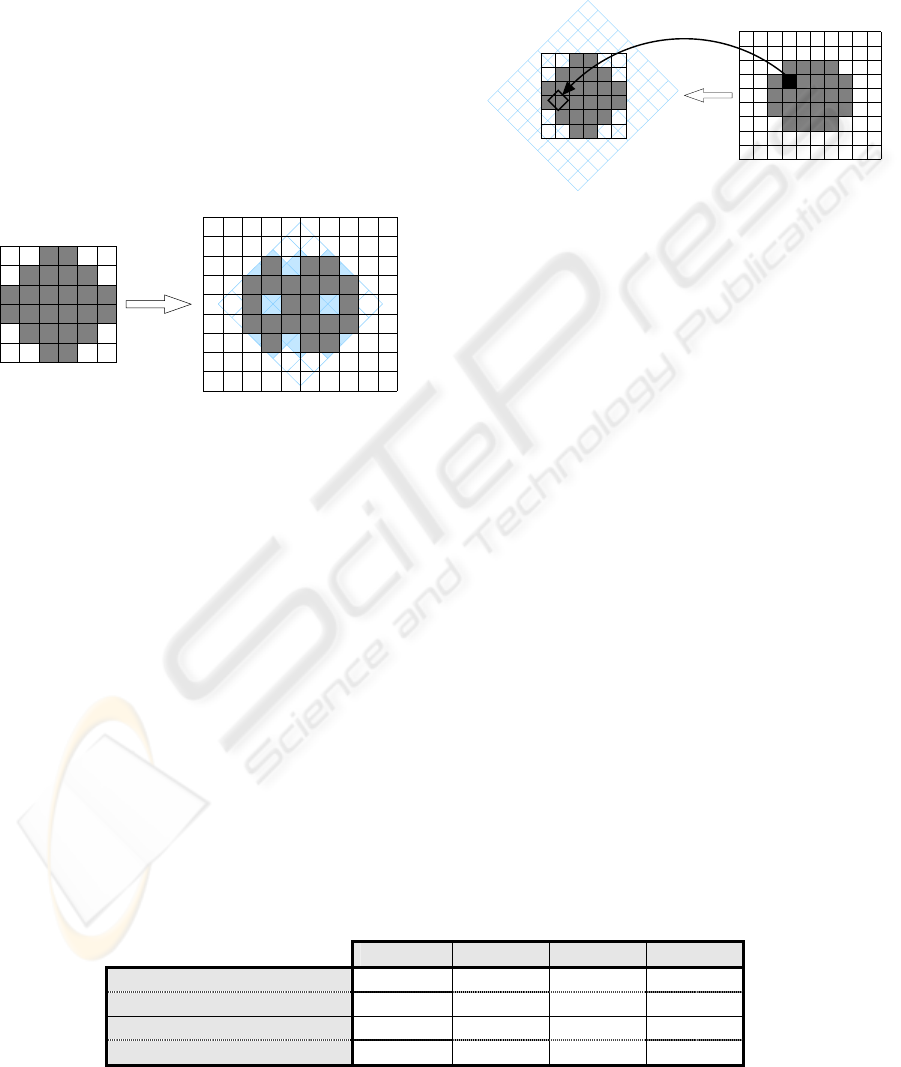
However, as we can see on figure 3, this results
in holes in the final image as many voxels from the
source can be projected to the same voxel in the
destination due to truncation error to integers.
Consequently, a direct rotation of the source image
is inadequate.
Initial Image
Final Image
Rotation
Matrix
Figure 3: The use of the direct method to compute the
rotation of a discrete image results in holes in the final
image.
3.1.3 Inverse Method
The solution is to perform the inverse mapping. We
consider each voxel in the final image and map
backwards to find the closest voxel in the initial
image by applying the inverse rotation matrix. In
this way, every voxel in the final image is found,
without hole (figure 4).
However, there are still two problems:
− First, the computation time of this “brute force”
rotation is high, as we multiply each voxel
position of the final image by the inverse
rotation matrix (Of course, this one is only
computed once). Computation time increases
with the size of the 3D image, i.e. with the
number of voxels.
− Second, there is important aliasing in the final
image.zasing.
The aliasing problem will be tackled in the
following section. In order to reduce computation
time to allow real-time tool rotation, we propose an
optimised rotation method with three improvements
over the “brute force” method.
Matrix
Initial Image
Final Image
Inverse
Rotation
Figure 4: With the inverse rotation method, no hole is
obtained in the final image.
First, we do not compute the inverse
transformation for all the voxels of the final image,
but only for 4 voxels defining 3 orthogonal axes.
Positions of all other voxels are computed by simple
interpolations from these 4 positions (algorithm 1).
Computation times have been reported on table 2.
Moreover, comparisons between computation times
with brute force method and optimised method have
been reported on graph 1, for a tool in 16x16x16.
We can see that with this optimisation the rotation
time is cut down by 75% compared to the “brute
force” method. We can see that the computation
times depend on angle of rotation because the
number of voxels needed to store the rotated tool
changes with the angle.
Second, we drastically cut down the computation
time by only performing the rotation for the voxels
of the tool that are in contact with the object to be
sculpted. Indeed, this rotation is only required for
internal needs to perform sculpture operations. For
the display of the tool, we do not compute the
discrete rotation of the voxels, but we simply use
OpenGL rotation capabilities with the
glRotate() function. Thus, we can display tools
with good rendering quality, without distortion due
to discrete rotation.
Third, in order to reduce furthermore the
computation times, we store the already rotated
Table 2: Computation times obtained with different methods for rotation of a discrete tool for different resolutions
(averaged times for various rotation angles).
8x8x8 16x16x16 32x32x32 64x64x64
Brute force 0.1826 ms 1.321 ms 10.17 ms 82.3 ms
Optimised 0.0456 ms 0.322 ms 2.49 ms 18.1 ms
Brute force with antialiasing 0.2303 ms 1.628 ms 12.45 ms 102.1 ms
Optimised with antialiasing 0.0494 ms 0.351 ms 2.55 ms 18.7 ms
DISCRETE TOOLS FOR VIRTUAL SCULPTURE
419
voxels in a cache structure. Thus, we avoid to
compute them again when the contact area between
the tool and the object has changed. We only
compute the rotation of the voxels of the tool newly
entered in the area.
Algorithm 1: Discrete rotation of the tool.
P = voxel in final image
M = point in initial image
M = Inverse_Rotation(P)
b = (i,j,k) = final basis
B = (I,J,K) = initial basis
B = Inverse_Rotation(b)
dim = voxels number along an axis
in final image
FOR P.x=0 TO dim.X DO
FOR P.y=0 TO dim.Y DO
FOR P.z=0 TO dim.Z DO
// Get the value of the
// voxel M in initial image
P = GetValue(M)
// Next point M
M.x = M.x + K.x
M.y = M.y + K.y
M.z = M.z + K.z
END FOR
// Return along axis K in
// initial basis.
// M is incremented with J
M.x = -dim.Z * K.x + J.x
M.y = -dim.Z * K.y + J.y
M.z = -dim.Z * K.z + J.z
END FOR
// Return along axis J in
// initial basis.
// M is incremented with I
M.x = -dim.Y * J.x + I.x
M.y = -dim.Y * J.y + I.y
M.z = -dim.Y * J.z + I.z
END FOR
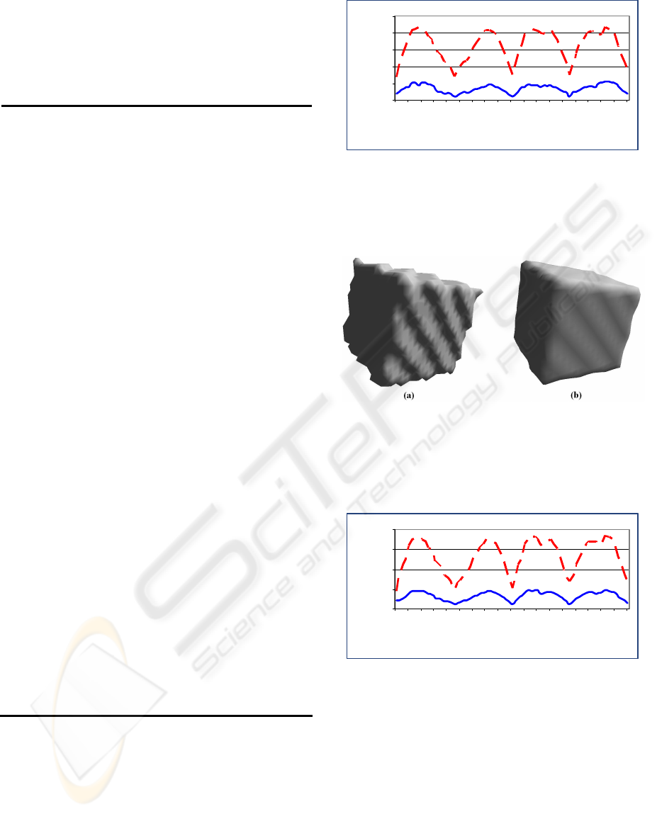
Please note that the computation times reported
on table 2, graph 1 and graph 2 are the times
observed in the worst cases, when all the voxels of
the tool have to be rotated (all voxels of the tool in
contact with the object and no voxel present in the
cache). In practical cases, the times are much lower.
0
0,5
1
1, 5
2
2,5
0 60 120 180 240 300 360
angles (degrees)
times (ms)
Graph 1: Comparison between computation times for
brute force method (dashed line) and optimised method
(solid line) for various rotation angles.
3.2 Antialiasing
Figure 5: A rotated cube without (a) and with antialiasing
by trilinear interpolation (b).
A major drawback of the rotation of a discrete image
is aliasing. The lower the image resolution, the more
important the aliasing (figure 5a).
0
0,5
1
1, 5
2
0 60 120 180 240 300 360
angles (degrees)
times (ms)
Graph 2: Comparison between computation times for
brute force method (dashed line) and optimised method
(solid line) with antialiasing for various rotation angles.
In order to reduce aliasing, we compute the value
of a rotated voxel from a trilinear interpolation of its
8 neighbours in the original image. Much better
results are obtained (figure 5b) to the price of
slightly higher computation times (On average,
+25% for the brute force rotation, +5% for the
optimised rotation as reported on Table 2). As for
graph1, we can see on graph 2 that the computation
times depend on angle of rotation.
GRAPP 2006 - COMPUTER GRAPHICS THEORY AND APPLICATIONS
420
3.3 Sculpture Operations
Thanks to the representation of the material to be
sculpted as a set of volume elements, we can easily
handle sculpture actions such as subtraction or
addition of material. Other sculpture actions will be
studied in future work. A major advantage of our
method is that the tool used for virtual sculpture has
the same representation than the material. So, the
user can create his or her own tools to sculpt another
3D object.
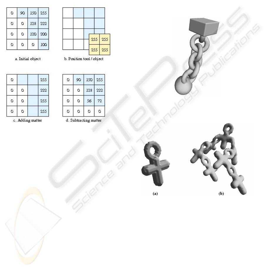
Figure 6: Adding or subtracting material to an object with
a tool.
During the sculpture operations, a collision test is
first made between the bounding boxes of the tool
and the material. If there is a collision, the following
operations are performed:
− Find the voxels of the material and the tool
which are in the collision zone.
− Extract the value of each voxel of the tool in the
collision zone by using the discrete rotation.
− Find which voxel of the tool intersects which
voxel of the material in this zone.
If there is intersection between voxels of the
material and the tool in the collision zone, we
compute the filling percentage of the voxel of the
material by the one of the tool. The values of the
voxels of the material are then modified according to
the sculpture mode (illustrated in 2D on figure 6):
− In the “Adding material” mode, if the voxel of
the tool isn’t null, the filling percentage is added
to the value of the voxel of the material. If this
value becomes greater than 255, it is put to 255.
− In the “Subtracting material” mode, if the voxel
of the tool isn’t null, the filling percentage is
subtracted to the value of the voxel of the
material. If this value becomes negative, it is put
to 0.
For each level of detail, the triangulated surface
is rebuilt by marching cubes only for the modified
parts of the 3D object to improve the computation
time.
Examples of sculptures produced by our system are
shown on figures 7 and 8.
Figure 7: Chain with a ball, in 256x256x256, sculpted
with a spherical tool, a cubic tool and a ring tool in less
than 10 minutes.
Figure 8: Design of a new tool (a) using a ring tool and a
spherical tool. A more complicated object (b) sculpted in
less than 5 minutes using the previously designed tool.
4 CONCLUSION
We have presented in this paper a model for virtual
sculpture of 3D objects with tools. Both objects and
tools are represented by 3D Haar wavelets. This
multiresolution model permits to avoid speed and
memory issues inherent to a representation based on
voxels. The discrete representation as volume
elements allows to handle easily sculpture
operations such as subtraction or addition of
DISCRETE TOOLS FOR VIRTUAL SCULPTURE
421

material. Unlike other existing virtual sculpture
methods, a major advantage of our model is that the
tools can freely be created by the user.
In order to allow any orientation of a tool over
the object to be sculpted, we have developed an
algorithm of discrete rotation of the tool in its 3D
matrix of voxels. In order to enhance real-time
performance, this algorithm is applied only for the
voxels of the tool that are in contact with the object
to be sculpted. Aliasing problems inherent to
discrete rotation are reduced thanks to a trilinear
interpolation to the cost of slightly higher
computation time.
To verify the applicability of our sculpting
system, we have conducted many sculpting sessions
which have resulted in numerous interesting
sculptures. Some sculptures examples are shown on
figures 7 and 8, and several other examples can be
seen on http://www.iut-arles.up.univ-mrs.fr/thon/.
5 FUTURE WORK
Many improvements of our sculpture system are
possible, by investigating open issues such as
interaction with the object or computation time.
Concerning interaction, we plan to improve the
realism of sculpture actions, by adding parameters to
the voxels to imitate physical behaviour. Enhanced
sculpture actions will then be possible.
Interactive computation times will always be a
challenging issue. In order to accelerate the
sculpture actions, we plan to take more advantage of
the levels of detail of the 3D Haar wavelet. We will
also investigate the use of graphics hardware to
speed up many parts of our system, such as voxels
rotation or sculpture actions.
REFERENCES
Ayasse, J., Müller, H., 2001. Interactive Manipulation of
Voxel Volumes with Free-formed Voxel Tools. In
Proceedings of the Vision Modeling and Visualization
Conference 2001, 359-366.
Bærentzen, J.A., Christensen, N.J., 2002. Volume
sculpting using the Level-Set method. In Shape
Modelling International 2002. IEEE Computer
Society, 175-182.
Bergen, G.V.D., 1997. Efficient collision detection of
complex deformable models using AABB trees. In
Journal of Graphic Tools, 2(4), 1-13.
Boada, I., Navazo, I., Scopigno, R., 2001. Multiresolution
volume visualization with a texture-based octree. In
Visual Computer, 17, 185-197.
Bradshaw, G., O’Sullivan, C., 2004. Adaptive medial-axis
approximation for sphere-tree construction. In ACM
Transactions on Graphics, 23(1), 1-26.
Ferley, E., 2002. Sculpture virtuelle. Ph.D. thesis, Institut
National Polytechnique de Grenoble.
Frisken, S.F., Perry, R.N., 2001. Kizamu: a system for
sculpting digital characters. In Proceedings of ACM
SIGGRAPH 2001, 47-56.
Gottschalk, S., Lin, M.C., Manocha D., 1996. OBB-Tree:
A hierarchical structure for rapid interference
detection. In Proceedings of ACM SIGGRAPH’96,
171-180.
Hubbard, P., 1995. Collision detection for interactive
graphics applications. Ph.D. Thesis, Dept. of
Computer Science, Brown University.
Hubbard, P., 1996. Approximating polyhedra with spheres
for time-critical collision detection. In ACM
Transactions on Graphics, 15(3), 179-210.
Libes, D., 1991. Modeling dynamic surfaces with octrees.
In Computer & Graphics, 15(3).
Liu, Y., Noborio, J., Arimoto, S., 1988. Hierarchical
sphere model (HSM) and its application for checking
an interference between moving robots. In
Proceedings of the IEEE International Workshop on
Intelligent Robots and Systems, 801-806.
Lorensen, W.E., Cline, H.E., 1987. Marching Cubes: a
high-resolution 3D surface construction algorithm. In
Computer Graphics, 21(4), 163-169.
Muraki, S., 1992. Approximation and rendering of volume
data using wavelet transforms. In Proceedings of
Visualization ’92, Boston, 21-28.
Muraki, S., 1993. Volume data and wavelet transforms. In
IEEE Computer Graphics and Applications, 13(4), 50-
56.
Pinnamaneni, P., Meyer, J., Saladi, S., 2002. Remote
transformation and local 3-D reconstruction and
visualization of biomedical data sets in Java3D. In
Proceedings of Electronic Imaging Science &
Technology Visualization and Data Analysis
Conference, San Jose, CA, 44-54.
Raffin, R., Gesquière, G., Remy, E., Thon, S., 2004.
VirSculpt: a virtual sculpting environment. In
GraphiCon '04 Proceedings, 184-187.
Szeliski, R., Tonnesen, D., 1992. Surface modeling with
oriented particle systems. In Computer Graphics,
26(2), 185-194.
GRAPP 2006 - COMPUTER GRAPHICS THEORY AND APPLICATIONS
422
