
ROBUST AUGMENTED REALITY TRACKING BASED VISUAL
POSE ESTIMATION
Madjid Maidi, Fakhr-Eddine Ababsa and Malik Mallem
IBISC Laboratory / CNRS FRE 2873
University of Evry
40 Rue du Pelvoux, CE 1455 Courcouronnes, 91020 Evry Cedex, France
Keywords:
Computer vision, augmented reality, calibration, pose estimation, robust tracking.
Abstract:
In this paper, we present a robust fiducials tracking method for real time Augmented Reality systems. Our
approach identifies the target object with an internal barecode of the fiducial and extracts its 2D features
points. Given the 2D feature points and a 3D object model, object pose consists in recovering the position and
the orientation of the object with respect to the camera. For pose estimation, we presented two methods for
recovering pose using the Extended Kalman Filter and the Orthogonal Iteration algorithm. The first algorithm
is a sequential estimator that predicts and corrects the state vector. While the later uses the object space
collinearity error and derives an iterative algorithm to compute orthogonal rotation matrices. Due to lighting
or contrast conditions or occlusion of the target object by an other object, the tracking may fail. Therefore, we
extend our tracking method using a RANSAC algorithm to deal with occlusions. The algorithm is tested with
different camera viewpoints under various image conditions and shows to be accurate and robust.
1 INTRODUCTION
In this study we develop a robust visual tracker
based pose estimation that handles occlusions in Aug-
mented Reality (AR) applications. Our proposed sys-
tem tracks coded fiducials, estimates the camera pose
sequentially to input scenes and deals with occlusions
of the target object when it is partially or not visible.
Among the various existing tracking methods, we
can quote 3 usually used generic methods. Gennery
method (Gennery, 1992) is the most intuitive, it pri-
marily consists to project the model and to adjust its
position in the image. This method is simple for im-
plementation but requires a good initialization. The
method of Lowe (Lowe, 1992) expresses the error ac-
cording to the pose parameters. This method con-
verges quickly but requires a good initialization of
pose parameters. Harris (Harris and Stennett, 1990)
exploits image points in addition to the points of in-
terest to make a tracking. His method appears more
precise and more complex than the 2 previous ones.
All methods presented previously, allow to track vis-
ible targets and do not manage occlusion. Other au-
thors were interested by the robustness aspect, thus,
Naimark and Foxlin (Naimark and Foxlin, 1990) im-
plemented a hybrid vision-inertial self-tracker system
which operates in various real-world lighting condi-
tions. The aim is to extract bar-coded fiducials in
the presence of very non-uniform lighting. In (Com-
port et al., 2003), the authors integrate a M-estimator
into a visual control law via an iteratively re-weighted
least squares implementation. The implementation
showed that method is robust to occlusion, changes
in illumination and miss-tracking. In (Chen et al.,
2003), the authors proposed also an algorithm based
M-estimator for speeding up the process of template
matching and dealing with outliers.
In this work, we define our fiducials, we make a
comparison between 2 pose estimators and we imple-
ment a tracking algorithm based RANSAC (Fischler
and Bolles, 1981) to deal with target occlusion.
The remainder of the paper is organized as fol-
lows. In section 2, object detection procedure is pre-
sented. Section 3 describes the principle of target ex-
traction using bar-coded fiducials. The camera cali-
bration procedure is presented in section 4. In section
4, we present pose estimation using 2 methods, the
OI and the EKF algorithm. In section 6, we detail the
principle of our robust tracking algorithm. Section 7
shows the obtained results. We conclude by section 8
where we present conclusion and future work.
2 OBJECT DETECTION
The first step of our work deals with image segmenta-
tion for shape detection. Our goal is to build an identi-
346
Maidi M., Ababsa F. and Mallem M. (2006).
ROBUST AUGMENTED REALITY TRACKING BASED VISUAL POSE ESTIMATION.
In Proceedings of the Third International Conference on Informatics in Control, Automation and Robotics, pages 346-351
DOI: 10.5220/0001216303460351
Copyright
c
SciTePress
fier model describing various object of interests struc-
ture. In order to reduce detection error rate, images
are pre-processed into an acceptable form before any
image analysis is carried out. The image is converted
into a black and white image using a suitable thresh-
old. Then, many operations are applied to process the
image and detect the object of interest
1. Apply Canny filter to detect contours in image
(Canny, 1986).
2. Smooth the image using a Gaussian filter to elimi-
nate pixel variations according to the contour seg-
ments by joining the average values.
3. Dilate the smoothed image to remove potential
holes between edge segments.
4. Approximate contour with accuracy proportional to
the contour perimeter.
5. Find the number of object vertices.
6. Identify object boundaries as 4 intersecting lines by
testing collinearity of vertices.
7. Find minimum angle between joint edges, if the
cosines of the 4 angles are small (≈ 0) then a square
is detected
Finally, only objects with 4 vertices and right angles
are retrieved and considered as square shapes. Once
a square object is detected, the next step is to identify
this object and match it with a defined template.
3 FIDUCIAL DESIGN AND
IDENTIFICATION
Our goal is to design fiducials which can be robustly
extracted in real time from the scene. Therefore, we
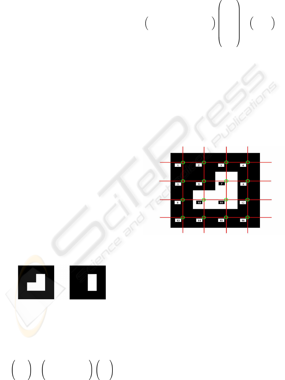
use 2 kind of square fidicials with patterns inside (fig-
ure 1), these fiducials contain a barcode used for tem-
plate matching.
Figure 1: Models of Fiducials.
The internal code of the fiducial is computed by
spatial sampling of the 3D fiducial model. Then, we
project the sample points on the 2D image using the
homography computed from the 4 vertices of the de-
tected fiducial with the following formula
su
sv
s
=
h
11
h
12
h
13
h
21
h
22
h
23
h
31
h
32
h
33
x
y
1
(1)
From equation 1 we can write
x y 1 0 0 0 −xu −yu
0 0 0 x y 1 −xv −yv
h
11
h
12
h
13
h
21
h
22
h
23
h
31
h
32
=
h
33
u
h
33
v
(2)
In order to obtain a non trivial solution, we must
fix one of the coefficients h
ij
to 1. In this study we
set h
33
= 1. The number of parameters to estimate
is 8, then we need 8 equations to solve our system.
Therefore we use 4 coplanar points which represent
the fiducial vertices in the image. This homography
allows the passage of a point from the 3D object co-
ordinate frame toward a 2D image coordinate frame.
We define a sampling grid of the fiducial model (fig-
ure 2) and we project these sampling points on 2D
image using the the computed homography.
Figure 2: Fiducial sampling.
We compute the fiducial corresponding code from
the sampling grid, this code is composed of 16 bits
and represents the fiducial samples color. Finally the
fiducial code can have 4 values following the 4 possi-
ble fiducial orientations.
4 CAMERA CALIBRATION
Our algorithm has been applied to estimate the ob-
ject pose in a sequence of images. In the experiments
we use a CCD camera IS − 800 model from i2S
with 8mm focal length. Before start working with
the camera we must calibrate it to determine its in-
trinsic and extrinsic parameters. The calibration pro-
cedure simulates the camera by a theoretical model
ROBUST AUGMENTED REALITY TRACKING BASED VISUAL POSE ESTIMATION
347
which describes the transformation of the scene (3D
objects) toward the image (Maidi et al., 2005).
The camera calibration determines the geometrical
model of an object and the corresponding image for-
mation system which is described by the following
equation (Zhang, 1998)
su
sv
s
!
= I
x
(
R T
)
X
Y
Z
1
(3)
where s is an arbitrary scale factor, (R, T ) called the
extrinsic parameters, is the rotation and translation
which relate the world coordinate system to the cam-
era coordinate system and I
x
called the camera intrin-
sic matrix given by
I
x
=
α
u
0 u
0
0 α
v
v
0
0 0 1
!
(4)
with (u
0
, v
0
) the coordinates of the principal point
and α
u
and α
v
the scale factors according to u and
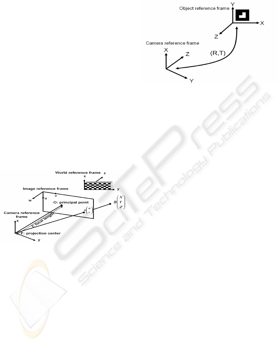
v image axes (figure 3).
Figure 3: Coordinate systems used in camera calibration
procedure.
I
x
is computed from the camera calibration proce-
dure and remains unchanged during the experiments.
The purpose of the work is to compute the extrinsic
matrix, (R, T ), which represents the camera pose.
5 POSE ESTIMATION
The main part of this work deals with the 2D-3D pose
estimation problem. Pose estimation is the determi-
nation of the position and orientation of a 3D object
with respect to the camera coordinate frame (figure
4).
In section 3, we presented our method of identify-
ing the object of interest. Now, we will develop the
Figure 4: Pose parameters: rotation and translation of the
object coordinate frame according to the camera coordinate
frame.
pose estimation algorithm used to compute the posi-
tion and the orientation of the camera according to the
object frame.
We have studied 2 algorithms of pose estimation,
the first is based on the Extended Kalman Filter (EKF)
where the measurement equation models the feature
points of object in image and the process model pre-
dicts the behavior of the system based on the current
state and estimates the position and orientation of the
object toward the camera coordinate frame. The sec-
ond algorithm is the Orthogonal Iteration (OI) algo-
rithm combined with an analytic pose estimator, the
OI method uses the object space collinearity error and
derives an iterative algorithm which computes orthog-
onal rotation matrices.
5.1 The Extended Kalman Filter
We have implemented the EKF algorithm to estimate
the transformation between the object and the camera
coordinate frames (figure 4). Based on the knowledge
of the feature point position in the camera frame, we
use the perspective projection matrix of the camera
M, where M = I
x
· (
R T
), to get the projected
image coordinates of this point.
u
i
= f (M, P
i
)
v
i
= f (M, P
i
)
(5)
where P
i
= (X
i
, Y
i
, Z
i
)
T
The EKF is composed of 2 steps, the first step is the
time update, the state vector and the error covariance
matrix are predicted using initial estimates. Once this
step is finished, they will become the inputs for the
measurement update (correction) step. With the up-
dated information, the time update step projects the
state vector and the error covariance matrix to the next
ICINCO 2006 - ROBOTICS AND AUTOMATION
348
time step (Welch and Bishop, 2004). By doing these
2 steps recursively, we successfully estimate the state
vector.
The object feature points are determined by the
fiducial identification algorithm (section 3). For the
EKF, we use 6 states representing the rotation an-
gles and the translation vector of the object coordinate
frame with respect to the camera coordinate frame
represented by x = (roll pitch yaw T
x
T
y
T
z
)
T
.
The measurement input are the image data of the fea-
ture points coming from the camera and given by
z = (u
1
u
2
u
3
u
4
v
1
v
2
v
3
v
4
)
T
, where each fea-
ture point is represented by (u
i
, v
i
).
5.2 The Orthogonal Iteration
Algorithm
The OI algorithm allows to dynamically determine
the external camera parameters using 2D-3D corre-
spondences established by the 2D fiducials tracking
algorithm from the current video image (Ababsa and
Mallem, 2004). The OI algorithm computes first the
object-space collinearity error vector (Lu et al., 2000)
e
i
=
I −
ˆ
V
i
(RP
i
+ T ) (6)
where
ˆ
V
i
is the observed line of sight projection ma-
trix defined by
ˆ
V
i
=
ˆv
i
ˆv
t
i
ˆv
t
i
ˆv
i
(7)
then, a minimization of squared error is performed
E (R, T ) =
n
X
i=0
ke
i
k
2
=
n
X
i=0
I −
ˆ
V
i
(RP
i
+ T )
2
(8)
The OI algorithm converges to an optimum for any
set of observed points and any starting point (Ababsa
and Mallem, 2004). However, in order to ensure the
convergence of the algorithm into the correct pose in
a minimum time, we initialize the pose by another an-
alytic pose estimator for each acquired image.
The analytic pose estimator needs 4 coplanar points
to provide a solution for equation 2. Equation 1 rep-
resents the transformation between a 3D point and its
projection in the image. This transformation or ho-
mography can be expressed as follows
H = I
x
(
R T
) (9)
From equations 2 and 9, the extrinsic parameters
for each image are computed
R
1
= λI
−1
x
h
1
R
2
= λI
−1
x
h
2
R
3
= R
2
× R
3
T = λI
−1
x
h
3
(10)
Where λ is an arbitrary scalar, h
i
= (h
1i
h
2i
h
3i
)
T
and R
i
= (R
1i
R
2i
R
3i
)
T
.
6 ROBUST TRACKING
In this section we propose a solution to solve the prob-
lem of target occlusion, we use both fiducials pre-
sented in section 3. The second fiducial model allows
to have a double number of points to track, that per-
mit to compute the homography in a worse case where
one of the targets object is completely occulted. The
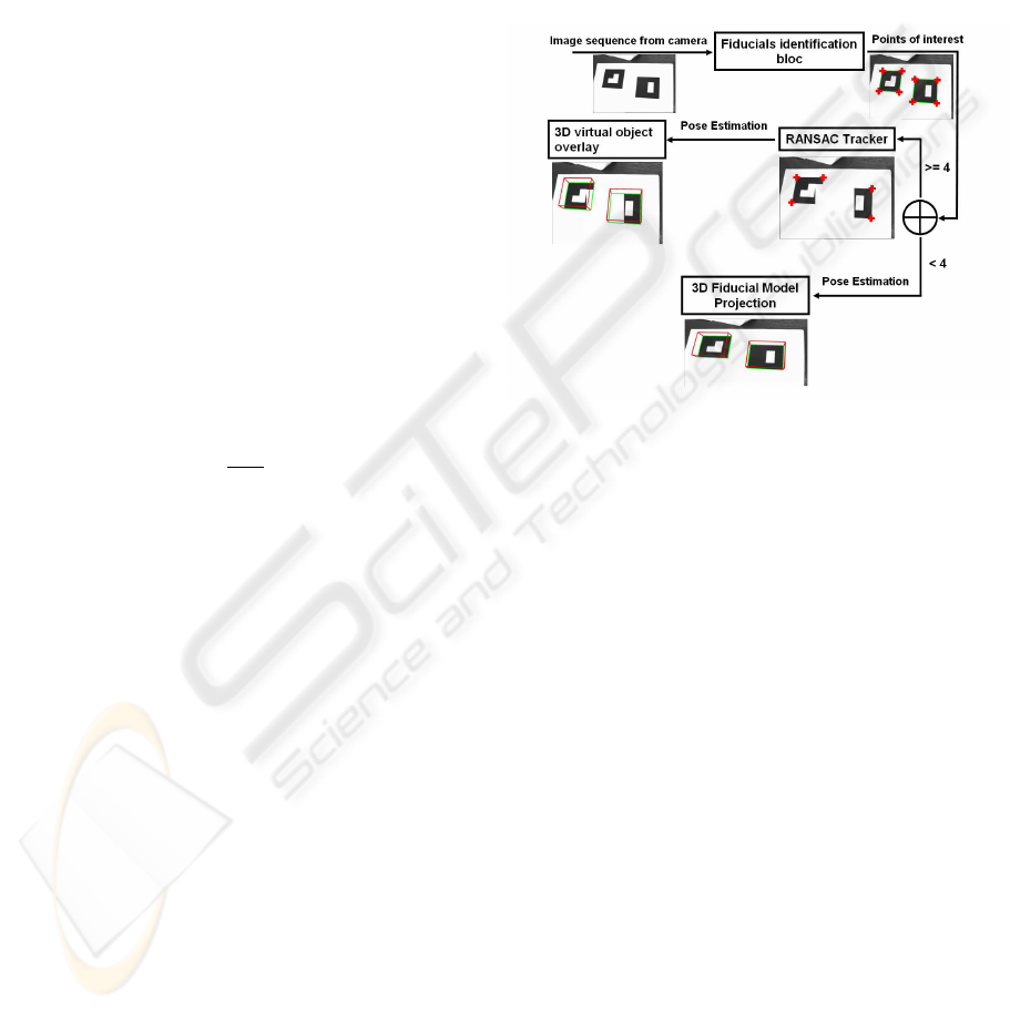
principle of the occlusion handling is explained in the
diagram of figure 5.
Figure 5: Robust tracking diagram.
We use 2 different types of fiducial models with 2
distinct codes. Initially, both fiducial models must be
visible by the camera to identify and extract their 4
feature points. Then, the robust algorithm of track-
ing is launched, it is based on RANSAC estimator to
track the 8 feature points of fiducials by computing a
rigid transformation between 2 successive images ac-
quired by the camera. RANSAC determines the cor-
respondence points between 2 images and in particu-
lar, allows to track the feature points of the fiducials
in course of time through the images. If one or more
points of the fiducials are occulted, the RANSAC al-
lows the tracking of the visible points by matching
them with points of the previous image. If both fidu-
cials are occulted the RANSAC fails and can’t track
the feature points any more, from where we must re-
project the 3D ficucial models on the current image
using the projection matrix of the camera. That will
allow an initialization of the tracking procedure.
7 RESULTS
For the experiments, we have used a single camera
with fixed internal parameters observing an object.
First we test the algorithm of fiducial identification
ROBUST AUGMENTED REALITY TRACKING BASED VISUAL POSE ESTIMATION
349
and pose estimation. We printed on a standard laser
printer 80 × 80 mm black and white fiducials. The
identification algorithm detects squares in image then
computes the barcode of the targets, if it matches with
template code, the target is identified (figure 6).
barcode = 544
barcode = 608
Figure 6: Fiducial objects identification with their barcodes.
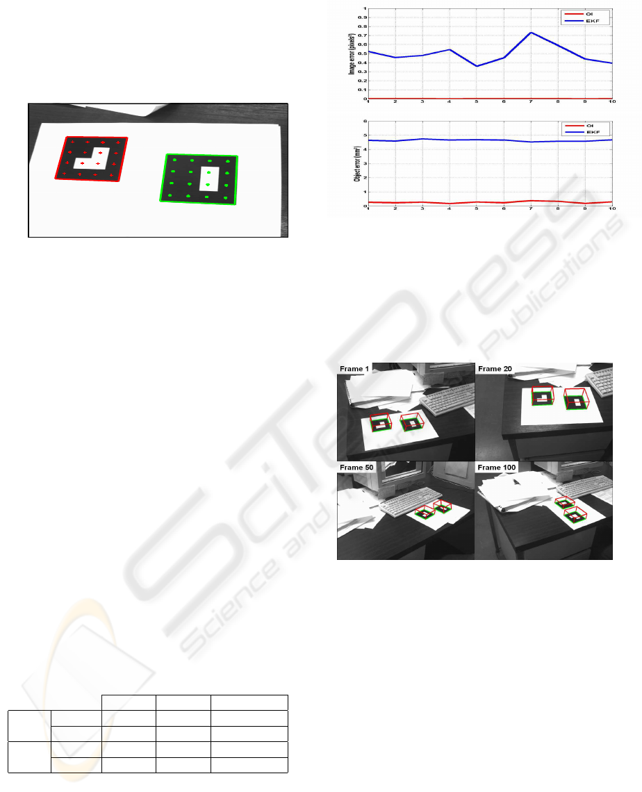
We tested the 2 algorithms of pose estimation on
several camera and fiducials positioning in the world.
In all configurations the 2 algorithms converge. How-
ever to measure the pose estimation errors using the
OI algorithm and the EKF algorithm, we project the
object features points on the image coordinate frame
using the estimated pose and compare them to the 2D
object features points (image error). We do the same
by projecting these 2D feature points to the object co-
ordinate frame using the estimated pose and we com-
pare with the real object position in the object coordi-
nate frame (object error), see figure 7. Table 1 shows
some estimated errors, standard deviation, variance
and mean error of the pose estimation results for a se-
quence of images where some frames are illustrated
in figure 8. It resumes the image and object obtained
pose errors from OI and EKF algorithms. The 2 algo-
rithms converge in few iterations and the error values
are clearly less in OI than in EKF, the time conver-
gence is also better in OI method where it is estimated
to be less than 5ms against 20ms for the EKF.
Table 1: Object and image errors in pose estimation (units:
object errors in mm
2
, image errors in pixels
2
).
std var mean error
OI
object 0.6154 0.3788 2.6524
image 5.1e-4 2.6e-7 0.0021
EKF
object 0.6508 0.4236 46.3400
image 0.1081 0.0117 0.4973
We estimate fiducials pose in different experiments
with real user motion. In the experiments we move
the camera around fiducials, the identification algo-
rithm detects and track targets in frames and the OI
algorithm computes the position and the orientation
Figure 7: Pose estimation errors: object and image projec-
tion errors in a tracking sequence.
of the feature points toward the camera. The proposed
tracking system was tested with image sequences cap-
tured under various camera positions (figure 8).
Figure 8: Overlaying a cube on the identified targets using
OI algorithm.
The second part of the experiments was to test the
robust tracking algorithm. Figure 9 represents cam-
era images used during our experiments in order to
analyze the performances of the robust tracking al-
gorithm. We initially made an extraction of feature
points in images using the Harris detector. From the
found correspondences, we retained only those corre-
sponding to the fiducial feature points computed by
the fiducial identification algorithm. Then, we car-
ried out an automatic matching of feature points of
fiducials between two successive images using the
RANSAC estimator which is a robust estimator re-
jecting outliers. We see also in figure 9 that the fidu-
cials are tracked even if they are occulted by other ob-
jects, if the number of feature points is at least equal
to 4. If both fiducials are occulted, the tracking algo-
ICINCO 2006 - ROBOTICS AND AUTOMATION
350

rithm stops and we must re-iniatilize the procedure by
a re-projection of fiducials on the current image using
the previous image homography.
Figure 9: Robust fiducial tracking.
8 CONCLUSION
In this paper, we were interested to robust and real
time tracking of fiducials in AR applications. We used
bar-coded object targets in order to identify fiducials
in images and extract their feature points. Thereafter,
we established the existing relationship between the
perspective model of camera, and we used 2 pose es-
timators which are the EKF and OI algorithm to de-
temine the right location of fiducials in the image. The
performance of OI algorithm were clearly better than
the EKF algorithm in term of errors and time execu-
tion. These performances justified throughly the use
of OI algorithm for the experiments, knowing that the
OI algorithm was initialized by pose parameters com-
puted by an analytic pose estimator.
We initially proposed an algorithm of feature points
tracking for a real time sequence of images based on
the object identification and pose computation. We
showed how to extend this method and make it robust
in the case of partial or total occlusion of the target by
using another algorithm based on RANSAC estima-
tor.
The obtained tracking results were precise, robust
and showed the validity of the used approach.
As perspective we will combine the camera with
an inertial measurement unit in order to locate this
hybrid system when the two target objects are com-
pletely occulted.
REFERENCES
Ababsa, F. and Mallem, M. (2004). Robust camera pose es-
timation using 2d fiducials tracking for real-time aug-
mented reality systems. Proceedings of ACM SIG-
GRAPH International Conference on Virtual-Reality
Continuum and its Applications in Industry (VR-
CAI2004).
Canny, J. (1986). A computational approach to edge de-
tection. IEEE Trans. Pattern Anal. Mach. Intell.,
8(6):679–698.
Chen, J. H., Chen, C. S., and Chen, Y. S. (2003). Fast algo-
rithm for robust template matching with m-estimators.
IEEE Transactions on Signal Processing, 51(1):36–
45.
Comport, A. I., Marchand, E., and Chaumette, F. (2003).
A real-time tracker for markerless augmented reality.
ACM/IEEE Int. Symp. on Mixed and Augmented Real-
ity (ISMAR 2003), pages 36–45.
Fischler, M. A. and Bolles, R. C. (1981). Random sample
consensus: a paradigm for model fitting with appli-
cations to image analysis and automated cartography.
Commun. ACM, 24(6):381–395.
Gennery, D. B. (1992). Visual tracking of known three-
dimensional objects. International Journal of Com-
puter Vision, 7(3):243–270.
Harris, C. and Stennett, C. (1990). Rapid – a video rate ob-
ject tracker. In Proc 1st British Machine Vision Conf,
pages 73–78.
Lowe, D. G. (1992). Robust model-based motion tracking
through the integration of search and estimation. Int.
J. Comput. Vision, 8(2):113–122.
Lu, C. P., , Hager, G. D., and Mjolsness, E. (2000). Fast
and globally convergent pose estimation from video
images. IEEE Transaction on Pattern Analysis and
Machine Intelligence, 22(6):610–622.
Maidi, M., , Ababsa, F., and Mallem, M. (2005). Vision-
inertial system calibration for tracking in augmented
reality. Proceedings of the Second International Con-
ference on Informatics in Control, Automation and
Robotics, ICINCO 2005, 3:156–162.
Naimark, L. and Foxlin, E. (1990). Circular data ma-
trix fiducial system and robust image processing for
a wearable vision-inertial self-tracker. IEEE Interna-
tional Symposium on Mixed and Augmented Reality
(ISMAR 2002), pages 27– 36.
Welch, G. and Bishop, G. (2004). An introduction to the
kalman filter. Technical Report No. TR 95-041, De-
partment of Computer Science, University of North
Carolina.
Zhang, Z. (1998). A flexible new technique for camera cal-
ibration. Technical Report MSR-TR-98-71.
ROBUST AUGMENTED REALITY TRACKING BASED VISUAL POSE ESTIMATION
351
