
NEUROLOGICAL AND ENGINEERING APPROACHES TO
HUMAN POSTURAL CONTROL
Karim Tahboub
College of Engineering and Technology, Palestine Polytechnic University, Hebron, Palestine
Thomas Mergner
Neurological Univ. Clinic, Neurocenter, University of Freiburg, Breisacherstr. 64,79106 Freiburg, Germany
Christoph Ament
Microsystems Engineerig, University of Freiburg, Georges-Koehler-Allee 103, 79110 Freiburg, Germany
Keywords: Human Postural Control, Modern Control, Neurological Control.
Abstract: This paper discusses the human postural control as
a system engineering approach problem. Two main
approaches are considered: neurological and engineering. From the neurological perspective, the problem is
described, main sensory systems are identified, sensor fusion is suggested, and control system architecture
and details are presented. Experimental results on both human subjects and on a special-purpose humanoid
agree with the presented architecture. On the other hand, the humanoid parameters are identified, the
humanoid dynamic model is derived, external-disturbance estimation methods are presented, a control
method for stabilizing the body motion and then for robust tracking of voluntary motion in the presence of
external disturbances is shown. This constitutes an engineering approach to this problem. Simulation results
are given and it is shown that the presented method is capable of estimating the disturbances and for
controlling the motion.
1 INTRODUCTION
Human upright stance is maintained by a posture
control mechanism the goal of which is to maintain
the orientation of the body upright and thereby the
center of mass (COM) above the base of the foot
support. The maintenance of body uprightness
during external stimuli is controlled mainly by a
sensory negative feedback mechanism (Johansson,
1991), which involves cues from visual, vestibular
and ankle angle proprioceptive receptors (Horak,
1996). Recent work that investigated the postural
responses of normal subjects and vestibular loss
subjects to body support motion and visual scene
motion has shown that the system can, in fact, be
described by a simple multisensory feedback model
(Mergner, 2003). Furthermore, postural responses to
external force stimuli in the form of pull were
described by means of a multisensory feedback
model (Mergner, 2003).
Mergner and his colleagues in Freiburg have
achi
eved profound results in understanding the
posture control mechanism from a system-theory
point of view. They identified the main sensors
involved, proposed a sensor-fusion-strategy
explanation, and suggested a control hierarchy
(Maurer, 2005). Clinical observations and results of
experiments with normal subjects and neurological
patients agreed with those obtained by simulation
using the developed “technical” model.
2 CONTROL PROBLEM AND
EXPERIMENTAL SETUP
The aim of neurological studies in posture control is
to understand the existing control processes and the
42
Tahboub K., Mergner T. and Ament C. (2006).
NEUROLOGICAL AND ENGINEERING APPROACHES TO HUMAN POSTURAL CONTROL.
In Proceedings of the Third International Conference on Informatics in Control, Automation and Robotics, pages 42-49
Copyright
c
SciTePress
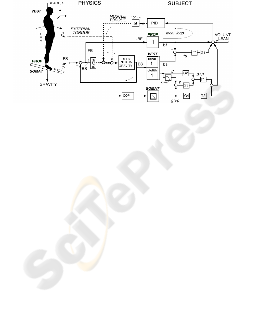
Figure 1: Multisensory model of posture control (from [3], slightly modified). The inset defines the ‘PHYSICS’ part of the
model (left) in terms of an ‘inverted pendulum body’ (one segment for head, trunk, and legs) that pivots about the ankle
joint on a potentially rotating platform (axis through the ankle joint). Pull on the body yields an ‘external torque’ stimulus
acting on the body, which indirectly adds to the ‘muscle torque’ at the ankel joint. FS, foot-in-space angle (resulting from
platform tilt); FB, foot-to-body angle (equal to -BF); BS, body-in-space angle). Box BIOM (for biomechanics) represents
the transformation of FB into ankle torque (in the present case passive viscous–elastic properties are assumed to be very
small as compared to external and muscle torques). Subjects’ anthropometric parameters are contained in the box ‘BODY
INERTIA, GRAVITY’. Dashed lines represent torque and solid lines angles. All delays in the system are represented as one
dead time (Δt). Ankle torque leads to a shift of the COP (box COP). The ‘SUBJECT’ part of the model (on the right)
establishes internal representations of the external stimuli (torque from gravitational and external pull on the body, and FS
angle), which are fed as set point signals, together with a voluntary signal (VOLUNT. LEAN), into a local proprioceptive
negative feedback loop for body-on-support control (loop indicated by thin arrows). PROP, proprioceptive sensor; VEST,
vestibular sensors (consisting of canal and otolith parts); SOMAT, plantar pressure cue (‘somatosensory graviceptor’; low-
pass frequency characteristics, corner frequency 0.8 Hz); somat’, internal model of SOMAT; bf, bs, and fs, internal
representations of BF, BS and FS, respectively; g, otolith-derived internal estimate of gravitational pull (g’, somatosensory
derived version of g); p, internal estimate of external pull; T1, T2, and T’, detection thresholds; G1–G4, gain of set point
signals (on the order of 0.7–0.9; held constant for all simulations of the results of normals).
causes of known abnormalities. This includes the
identification of sensory systems and components,
the sensor fusion process, the control architecture
and subsystem, and the actuators. Recently, there
has been an effort in quantizing this medical
knowledge (or theories) in terms of a mathematical
description (van der Kooij, 2001). It is evident that
the aim of these studies is not to design but to
analyze and understand the behavior of the system.
The behavioral scenario should not only comprise
small body excursions but also volitional action
(voluntary body lean) in the presence of external
perturbations (force field, gravity; contact force, pull
on the body; motion of support surface, platform tilt).
Superposition of all external perturbations should be
allowed where stable performance is still anticipated.
A multisensory posture control model that
demonstrates a nonlinear sensor fusion strategy
(with some thresholds) and a PID controller (with
saturation and time delay) is proposed by Mergner et
al. (Mergner, 2003). Fig. 1 shows the whole
architecture. In this model, three sensory systems are
used; gains, time delay, and thresholds are derived
from medical evidence. As to the model in its
original form, neither the architecture (structure) nor
the parameters were derived using any mathematical
model or by any modern control theory technique.
Yet, simulation results obtained by employing the
model explained the medical observations including
abnormalities in patients.
To avoid the difficulty in comparing simulation
results with clinical results, a humanoid robot is
pioneered (Fig. 2); it is built for the special purpose
of addressing the posture control question. Its
structure, dimensions, and parameters are selected in
accordance with those known for human postural
NEUROLOGICAL AND ENGINEERING APPROACHES TO HUMAN POSTURAL CONTROL
43
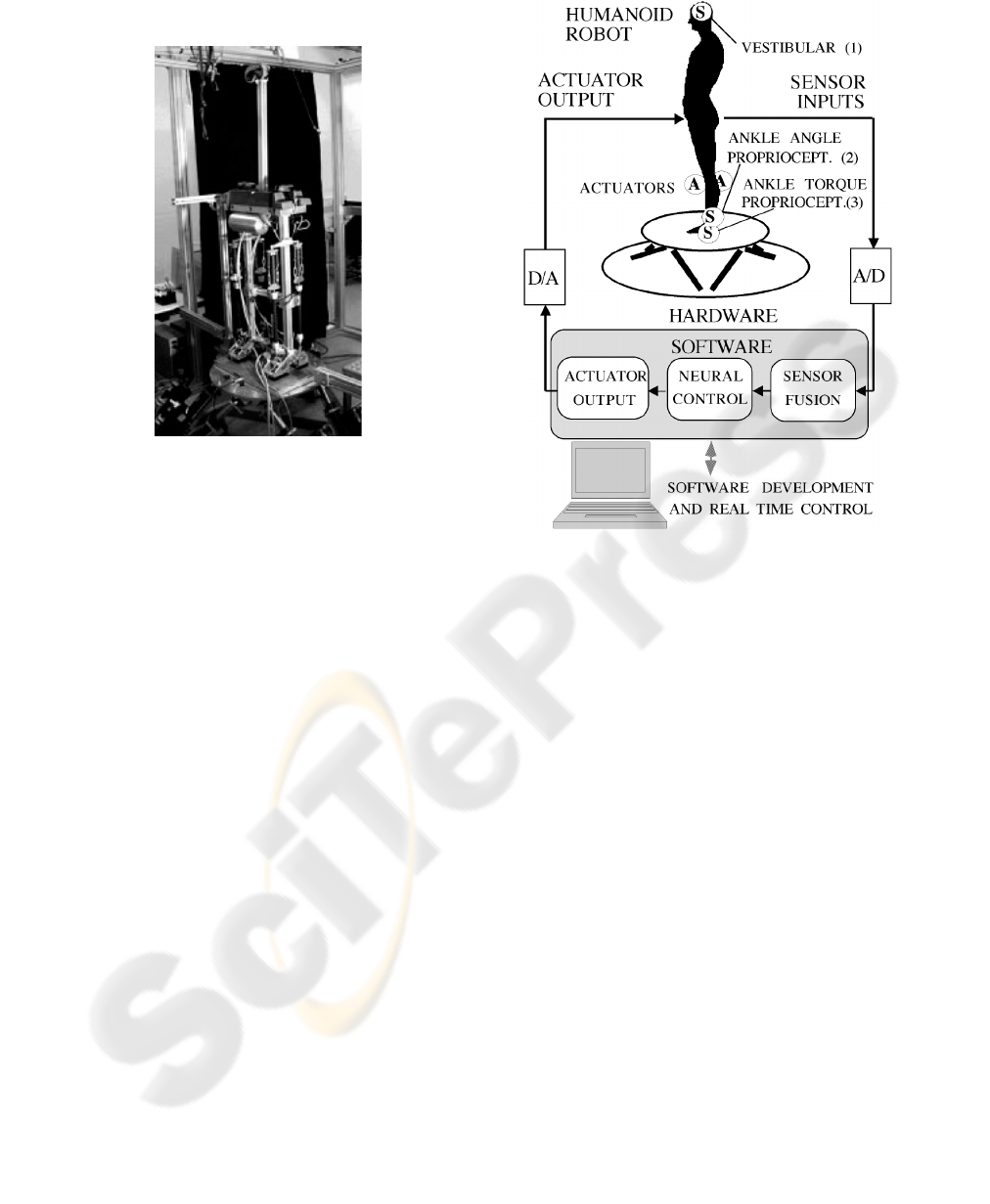
system. It is equipped with three sensor systems:
vestibular system (involving a 3D accelerometer and
Figure 2: Photograph of humanoid robot ‘PostuRob’
standing on motion platform. Its aluminum skeleton
consists of two rigid legs fixed to a pelvic girdle and a
spine (‘body’). Center of mass is mainly represented by
two plumb weights on pelvis. Each leg carries a front and
back ‘muscle’ to move the body with respect to the foot
about the ‘foot-ankle’ joint.
a 3D gyrometer), joint-angle sensor (placed at the
foot-ankle joint), somatosensory foot sole pressure
receptors (for measuring COP shifts; this measure is
equivalent to ankle joint torque). Furthermore, it is
actuated with pneumatic actuators that generate
forces of the same order as in humans. This
humanoid is integrated to be the core of a hardware-
in-the-loop simulation environment (Fig. 3.)
3 CONTROL ENGINEERING
APPROACH
A traditional model-based control approach is
selected to tackle the posture control problem. The
aim of the current study is to design a state and
disturbance estimator as well as to design a
controller that is capable of stabilizing the system
and achieving desired voluntary motion even in the
presence of the above mentioned disturbances. The
control system is tested by using the humanoid robot
model while taking the physical constraints (actuator
saturation) in consideration. The ultimate goal of
this part is not the control of the humanoid itself but
the comparison with the human control. For this, the
Figure 3: Hardware-in-the-loop simulation with actuators
(A) and sensors (S).
humanoid is modeled as two rigid bodies (the foot
and the body) connected together with a revolute
joint (foot-ankle joint) and actuated with pneumatic
actuators (front and back sides) that apply forces on
the body and reaction forces on the foot; the front
and back forces produce the actuating torque. The
foot rests on a movable platform (the same used for
testing human subjects). Two foot reaction forces
due to the weight and the dynamic forces can be
measured by force sensors. Since the platform is
allowed to tilt and external forces are allowed to pull
the body, not only COP, but also a friction force
between the foot and the platform is anticipated. The
centers of mass of the foot and of the body are
assumed to have some eccentricity from the vertical
centerline passing through the joints. Fig. 4 shows
the two rigid bodies, the actuators and the main
acting forces. Experiments are designed to measure
and identify the humanoid parameters as given in
Table 1.
3.1 Modeling
The major forces acting on the humanoid are shown
in Fig. 4. These include the reaction forces
F
F
and
ICINCO 2006 - ROBOTICS AND AUTOMATION
44
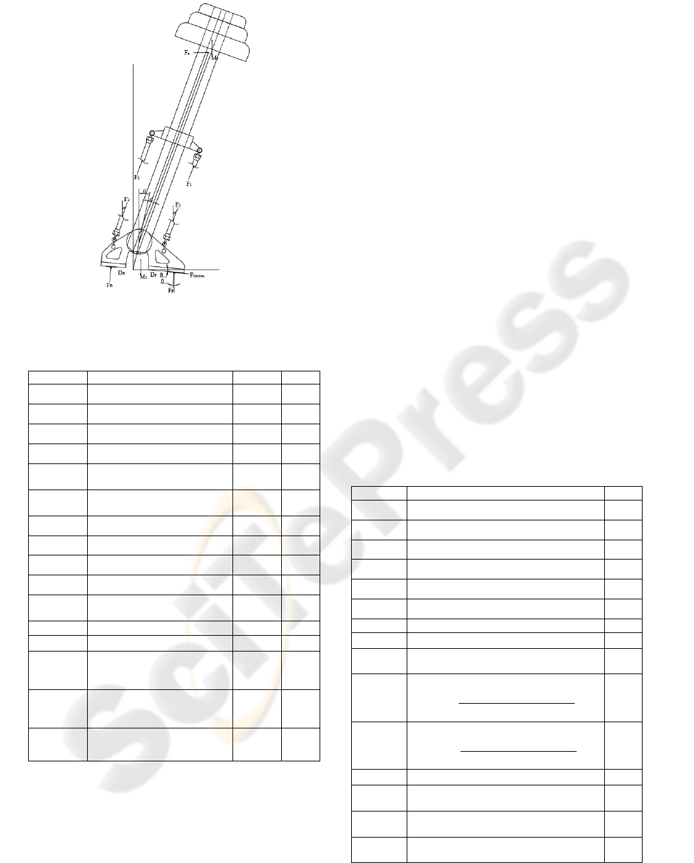
Figure 4: Main forces acting on the humanoid (drawing is
not to scale).
Table 1: Humanoid Parameters.
Parameter Meaning Value Unit
1
m
Mass of foot 8.6349 kg
2
m
Mass of body 90.724 kg
1
M
Weight of foot 84.7 N
2
M
Weight of body 890 N
F
D
Front force sensor distance to
centerline of foot
0.1475 m
B
D
Back force sensor distance to
centerline of foot
0.1025 m
1
h
Height of foot COM 0.0360 m
1
w
Eccentricity of foot COM 0.0121 m
2
h
Height of body COM 0.8500 m
2
w
Eccentricity of body COM 0.0018 m
a
h
Height of vestibular sensor
set
0.8000 m
L
Distance to body COM 0.8500 m
d
Height of foot-ankle joint 0.1080 m
D
Distance from centerline to
actuating force point of
application
0.1000 m
c
D
Height from foot-ankle joint
to actuating force point of
application on body
0.4230 m
γ
Angle to body COM;
( )
22
tan( ) /wh
γ
=
0.0021 rad
B
F
, the friction force beneath the foot, the weight,
the centrifugal and the inertia forces. Writing the
motion equations for the two rigid bodies (the foot
and the body) while assuming an external force
e
F
acting on the body and a tilting platform with
angle
θ
and then canceling the internal reaction
forces acting at the joint yields:
12
2
22
12
2
22
11 1
2
2
22
()sin()cos()
cos( ) sin( )
()cos()sin()
sin( ) cos( )
( sin( ) cos( )
sin( ) cos( )
cos( ) sin(
friction e
FB e
FF BB
e
FMMF
mL mL
FF MM F
mL mL
DF DF M h w
Md Fd
mLd mLd
θθ
ααγ ααγ
θθ
ααγ ααγ
θθ
θθ
ααγ α α
=+ +
−−+ −
+=+ −
−−− −
−= +
++
−
−+ −
11 2 2
212
2
)
cos( ) cos( )
(cos())
sin( )
ee
FDF D
I FDFDFh d
ML
γ
γγ
αθ
αθγ
+−
=− + + −
++−
(1)
The variables notation is listed in Table 2. It is noted
here that the effect of body motion appears in the
reaction forces which can be measured. Further, the
angle
α
is measured by the joint-angle sensor.
Finally, the vestibular (accelerometer) sensor which
is placed at the known height provides two
orthogonal acceleration quantities; these can be
transformed to absolute coordinates to yield:
a
h
(
x
ya
ag
ahg
)
α
αθ
=
=
++
(2)
where
g
is the gravitational acceleration constant.
Table 2: Humanoid Variables.
Variable Meaning Unit
f
riction
F
Friction force between foot and platform N
F
F
Measured reaction force at the foot front N
B
F
Measured reaction force at the foot back N
e
F
External pull force (disturbance) N
1
F
Front actuating force N
2
F
Back actuating force N
α
Body angle relative to foot rad
α
Body angular velocity relative to foot rad/s
α
Body angular acceleration relative to foot
rad/s
2
1
γ
Front actuator angle
1
sin( ) (cos( ) 1)
tan( )
cos( ) sin( )
c
c
DD
DD
αα
γ
αα
+−
=
−
rad
2
γ
Back actuator angle
2
sin( ) (1 cos( ))
tan( )
cos( ) sin( )
c
c
DD
DD
α
α
γ
αα
+−
=
+
rad
θ
Platform tilt angle (external disturbance) rad
e
h
Height of external pull force application
point
m
x
a
Measured acceleration in the vertical
direction
m/ s
2
y
a
Measured acceleration in the horizontal
direction
m/ s
2
NEUROLOGICAL AND ENGINEERING APPROACHES TO HUMAN POSTURAL CONTROL
45

3.2 Estimation of External
Disturbances
The main difficulties to control are the nonlinear
dynamics as presented in the above equations and
the presence of external disturbances that are not
directly measurable. Since foot-ankle angle (and
angular velocity), an acceleration at a known point,
and reaction forces are measurable, then it should be
possible to estimate these external disturbances
including the pull force and the platform tilt. The
estimation can be done either by solving the
equations for the unknowns or by the means of an
extended observer. The former option requires
solving the nonlinear equations numerically as an
analytical solution is difficult to obtain. The latter
option can be realized after linearizing the dynamics.
3.3 Linearization
Since the voluntary motion is limited to a few
degrees around the upright stance, the equations
describing the dynamics of the humanoid can be
linearized to yield:
12 2
12 2
11 1 2
212
212
2
()
()
()
()
()
friction e
FB
FF BB e
ee
FMMF
FF MM mL
DF DF M h w Md Fd
mLd FD FD
IFDFDFh
ML
θα
αγ
θθ
α
α
αθγ
=++−
+=++
−= +++
−+−
=− + + −
++−
mL
d
(3)
These equations which represent a linear time-
invariant system can be expressed in state-space
form as:
N N
N
1
23
21
22
22
2
22
01 0 0
()
1
0
00
u
xx
B
AH
e
e
HH
DF F
ML ML
II
F
hd ML
II
αα
2
I
θ
αα
γ
⎡⎤⎡⎤ ⎡
⎡⎤ ⎡⎤
⎢⎥⎢⎥ ⎢
=+−+
⎢⎥ ⎢⎥
⎢⎥⎢⎥ ⎢
⎣⎦ ⎣⎦
⎢⎥⎢⎥ ⎢
⎣⎦⎣⎦ ⎣
⎡⎤⎡⎤
⎢⎥⎢⎥
++
−
⎢⎥⎢⎥
⎢⎥⎢⎥
⎣⎦⎣⎦
⎤
⎥
⎥
⎥
⎦
(4)
where the first part (
x
Ax Bu=+
) describes a linear
system superimposed by the effect of external
disturbances (
, ,
e
F
θ
γ
). Note that the eccentricity
in the body COM (represented by
γ
) causes a tip
over effect
.
3.4 Control Law
Assuming that the external disturbances can be
estimated, then their effect can be compensated by
the control torque input . Having done this, one
obtains a simple linear system of second order for
which the problem of robust tracking and
disturbance rejection can be solved by the means of
a classical PID controller. So, the control input
u
has two parts: the first to compensate for the
external disturbances while the second to achieve
desired closed-loop performance:
u
d
u
l
u
(( ) ( ))
2
((
uFhdML
ee
u
d
kkk d
pv id
u
l
θγ
αα αα
=− − + −
−++ −
∫
))
t
(5)
where
d
α
is the desired “voluntary” body motion
and
e
F
θ
denote the estimates of and
e
F
θ
respectively.
, , and
p
v
kk k
i
denote the position,
velocity, and integral (robust tracking) feedback
gains respectively. These gains are found by solving
either a pole-placement or an optimal control
problem. Since usually a voluntary motion is
specified relative to an absolute frame (rather than
relative to the platform), the summation of
and
α
θ
becomes the reference input. For this, the
desired
d
α
is obtained by subtracting the estimated
platform tilt angle
ˆ
θ
from the desired reference.
3.5 Extended Estimation
The linearized equation (4) can be rewritten in an
extended form as:
N
N
22
222
2
22
010 0
0
000 0
000 0
00
1
00
00
e
e
e
e
e
e
e
x
x
A
B
ML ML h d
III
F
F
ML
u
II
α
α
α
α
θ
θ
γ
⎡⎤
⎡⎤
⎡⎤
⎢⎥
−
⎢⎥
⎢⎥
⎢⎥
⎢⎥
⎢⎥
⎢⎥
=
⎢⎥
⎢⎥
⎢⎥
⎢⎥
⎢⎥
⎢⎥
⎢⎥
⎢⎥
⎣⎦
⎣⎦
⎢⎥
⎣⎦
⎡⎤
⎢⎥
⎢⎥
−
⎡⎤
⎢⎥
+
⎢⎥
⎢⎥
⎣⎦
⎢⎥
⎢⎥
⎣⎦
(6)
ICINCO 2006 - ROBOTICS AND AUTOMATION
46
where the external disturbances are considered as
step-wise constant states. The five possible
measurements can be collected in the form:
1
2
2
22
1
2
2
2
1
3
2
4
22
5
2
2
22
2
2
2
22
11
2
00
00
0
(1 )
0
0
0
10 0 0
01 0 0
0
e
FF BB
aa
y
friction
D
mLd
mM Ld
y
y
I
I
u
DF DF
Mw
y
hMLh
a
y
II
y
F
mL
mM L
I
I
mM Ld
Mh
I
α
α
γ
⎡⎤
⎢⎥
⎢⎥
⎡⎤
⎡⎤
⎡⎤
−+
⎢⎥
⎢⎥
⎢⎥
⎢⎥
⎢⎥
⎡⎤
⎢⎥
⎢⎥
⎢⎥
−
== +
⎢⎥
⎢⎥
⎢⎥
⎢⎥
⎢⎥
⎣⎦
−
⎢⎥
⎢⎥
⎢⎥
⎢⎥
⎢⎥
⎣⎦
⎣⎦
⎣⎦
⎢⎥
−
⎢⎥
⎣⎦
−+
+
()
N
2
222
2
22
22
22 2
22
2
22 22
12
222
()
()
0
01
e
e
e
aaea
e
x
e
C
mLd h d
mM Ld
Md d
II
MLh MLh h dh
gg
F
II I
mL h d
mM L mM L
MM
III
α
α
θ
⎡⎤
⎢⎥
⎢⎥
−
−−
⎢⎥
⎡
⎤
⎢⎥
⎢
⎥
−
⎢⎥
⎢
⎥
++
⎢⎥
⎢
⎥
⎣
⎦
⎢⎥
−
⎢⎥
−+−−
⎢⎥
⎣⎦
(7)
It is straight forward to prove that the above system
is observable with the measurements
together with any third
measurement or any combination of
them. An estimator based on the above equation
yields estimates for the states
1
and yy
2
5
34
, , or yyy
and
e
F
θ
which are
used in the control law
(5).
3.6 Simulation Experiments
To test the validity of the above control and
estimation strategy, a simulation experiment is
designed. It is desired that the body moves
voluntarily in the absolute space according to this
function:
() 3sin(0.2
desired
t )
α
θ
+=
π
(8)
in the presence of a tilting platform according to:
3sin(0.4 )t
θ
π
= (9)
and an external pulse pull force
e
F
with a magnitude
of and a duration of
5 s Further, a time
delay of
10 is assumed at the controller-actuator
side and a saturation of
100 is imposed on the
actuator. At this end, the whole system comprised of
the nonlinear plant, the extended estimator, and the
robust tracking and disturbance compensator is built
using the SIMLULINK environment. While the
eigenvalues of the extended estimator are kept
constant, different measurements are assumed. The
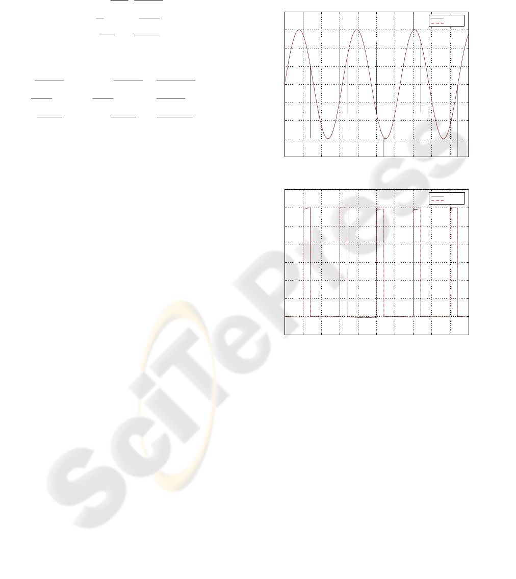
estimator works well for all tested combinations.
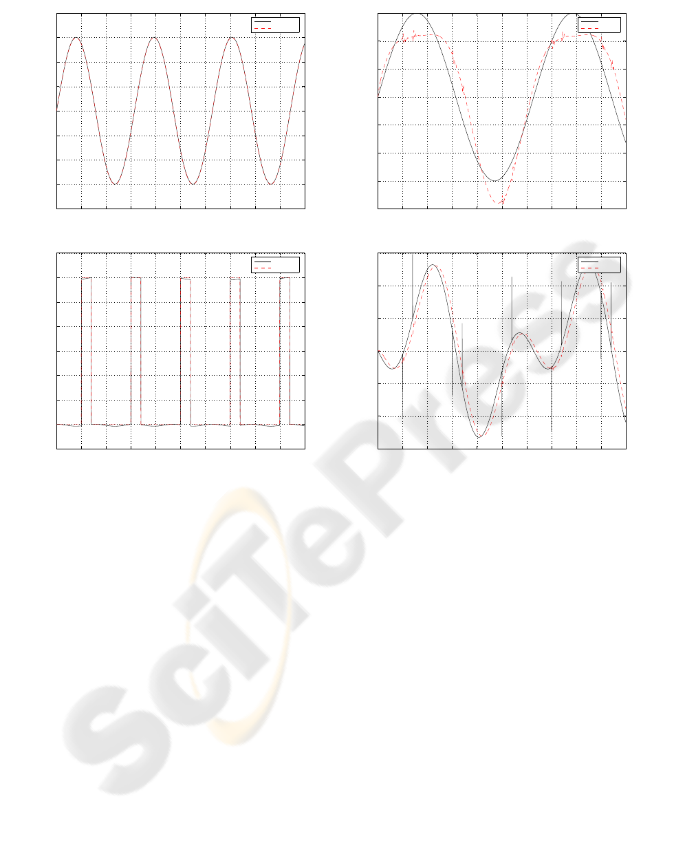
Figure 5 shows the actual disturbances and their
estimates obtained by measuring
30 N ec.
0ms
.Nm
, , and .
F
FBB
DF DF
α
α
−
Both of the estimates
match the actual disturbances very well except at the
moment of applying the external force.
0 10 20 30 40 50 60 70 80 90 10
0
−4
−3
−2
−1
0
1
2
3
4
Time [sec]
Platform tilt angle [deg]
Estimated and actual platform tilt angle
Actual
Estimated
A
0 10 20 30 40 50 60 70 80 90 10
0
−5
0
5
10
15
20
25
30
35
Time [sec]
Pull force [N]
Estimated and actual pull force
Estimated
Actual
B
Figure 5: Actual and estimated external disturbances
based on the measurement of
, , and .
F
FBB
DF DF
α
α
−
The estimated and actual platform tilt angle is shown in
(A); the estimated and actual external pull force is shown
in B.
The peaks observed in the estimate of the tilt
angle are reduced when using the
, , and
y
a
α
α
measurement and eliminated when
using all measurements combined as shown in
Figure 6.
In all cases the proposed control algorithm
performs well in tracking the desired motion as
shown in Figure 7 which corresponds to the
configuration where only one measurement is used.
NEUROLOGICAL AND ENGINEERING APPROACHES TO HUMAN POSTURAL CONTROL
47
0 10 20 30 40 50 60 70 80 90 10
0
−4
−3
−2
−1
0
1
2
3
4
Time [sec]
Platform tilt angle [deg]
Estimated and actual platform tilt angle
Actual
Estimated
A
0 10 20 30 40 50 60 70 80 90 10
0
−5
0
5
10
15
20
25
30
35
Time [sec]
Pull force [N]
Estimated and actual pull force
Estimated
Actual
B
Figure 6: Actual and estimated external disturbances
based on all measurements combined. The estimated and
actual platform tilt angle is shown in (A); the estimated
and actual external pull force is shown in B.
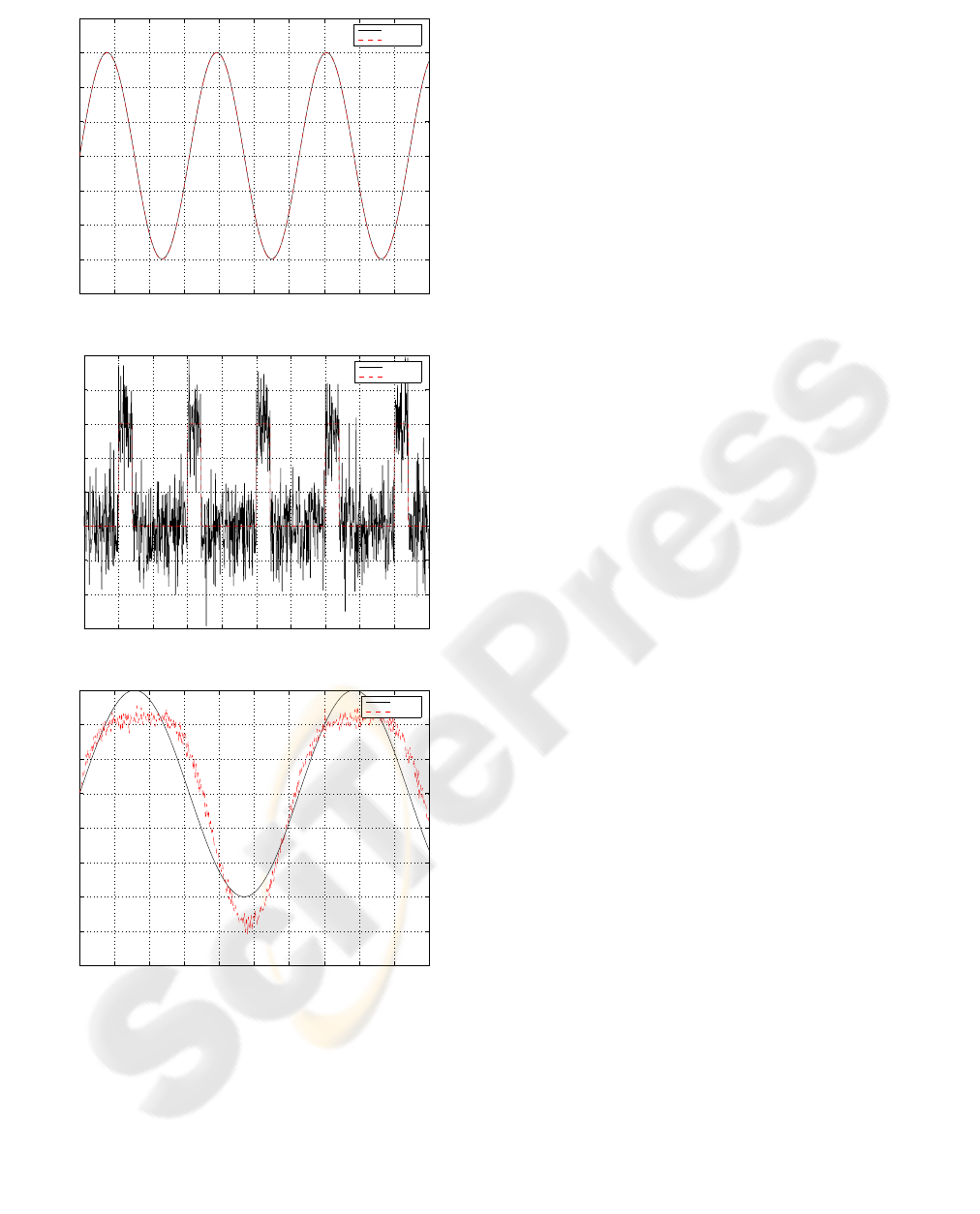
Finally, the effect of measurements noise is
investigated. A white noise of about 10% of the
signal is added to all measurements. The control
system is proved to be robust against measurement
noise especially the non-force measurements.
However, it is noticed that the performance
deteriorates when the force sensors become too
noisy. Figure 8 shows simulation results at the
presence of measurement noise assuming that all
measurements are used. The proposed control
strategy proves to be robust against sensor noise.
4 DISCUSSION, CONCLUSION,
AND FURTHER WORK
The human posture control problem is studied from
neurological and engineering perspectives. The aim
0 10 20 30 40 50 60 70 80 90 10
0
−4
−3
−2
−1
0
1
2
3
Time [sec]
Body angle [deg]
Desired and actual body angle in absolute space
Desired
Actual
A
0 10 20 30 40 50 60 70 80 90 10
0
−6
−4
−2
0
2
4
6
Time [sec]
Body angle [deg]
Desired and actual body angle relative to foot
Desired
Actual
B
Figure 7: Simulation results for the humanoid with
voluntary motion and external pull force in the presence of
platform tilting. The external disturbances are found by
the means of an extended observer that estimates both the
states and the disturbances. Time delay of 100 millisecond
is inserted between the controller and the actuator. The
desired and actual voluntary motion in absolute space is
shown in A; the desired and actual voluntary motion of the
body relative to the foot is shown in B.
of neurological studies is to analyze and understand
the human posture control mechanism and to find
models that are capable of explaining this behavior
and its abnormalities. This has been the focus of
dedicated medical and biological research groups.
The results obtained by the workgroup in
Freiburgfollowed the system engineering approach
as mentioned in this paper. Although the methods
applied by the neurological group do not follow in
all respects the currently used approaches in control
engineering, they still function very well and also
explain abnormalities. A first attempt is made, in
this article, to tackle the problem from a modern
control engineering point of view. Thus, a model-
ICINCO 2006 - ROBOTICS AND AUTOMATION
48
0 10 20 30 40 50 60 70 80 90 10
0
−4
−3
−2
−1
0
1
2
3
4
Time [sec]
Platform tilt angle [deg]
Estimated and actual platform tilt angle
Actual
Estimated
A
0 10 20 30 40 50 60 70 80 90 10
0
−30
−20
−10
0
10
20
30
40
50
Time [sec]
Pull force [N]
Estimated and actual pull force
Estimated
Actual
B
0 10 20 30 40 50 60 70 80 90 100
−5
−4
−3
−2
−1
0
1
2
3
Time [sec]
Body angle [deg]
Desired and actual body angle in absolute space
Desired
Actual
C
Figure 8: Actual and estimated external disturbances based
on all measurements combined at the presence of sensor
noise. The estimated and actual platform tilt angle is
shown in (A); the estimated and actual external pull force
is shown in B; the desired and actual voluntary motion in
absolute space is shown in C.
based approach is followed. A dynamic model for
the special-purpose humanoid is derived, an
external-disturbance estimation method is presented,
and finally a control method to compensate for
estimated disturbances, to stabilize the system, and
to achieve desired voluntary motion is used.
Simulation results are promising. From a pure
engineering perspective, the following results can be
briefly stated:
1. Currently, it appears possible to use only one
measurement (in addition to the foot-ankle
measurements) for the purpose of estimating the
disturbances and for controlling the motion.
2. It becomes necessary to use more measurements
in the presence of sensor noise especially
affecting the force sensors.
3. It is more beneficial to the estimation process to
use the foot-platform tangential contact force
(friction force) rather than the sum of the
vertical ones.
4. A linear controller can be used if the external
disturbances are estimated and compensated for.
In the future, the following remaining legitimate
questions should be tackled and answered:
1. How well does the presented method perform
when applied to the real (robot) system?
2. What are the similarities and differences
between the two presented models?
3. What is necessary to transform one model into
the other?
Once these questions are answered, engineers can
anticipate applying neurological knowledge in the
field of human posture control to engineering
application areas as humanoids and walking
machines and vice versa.
REFERENCES
Johansson R, Magnusson M (1991) Human postural
dynamics. Biomed Eng 18:413–437
Horak FB, Macpherson JM (1996) Postural orientation
and equilibrium. In: Rowell L, Shepherd J (eds)
Handbook of physiology, 1, exercise: regulation and
integration of multiple systems. Oxford University
Press, New York, pp 255–292
Mergner T, Maurer C, Peterka RJ (2003) A multisensory
posture control model of human upright stance. In:
Prablanc C, Pe´ lesson D, Rossetti Y (eds) Neural
control of space coding and action production. Prog
Brain Res 142:189–201
Maurer C, Mergner T, Peterka R.J (2005) Multisensory
control of human upright stance. Exp Brain Res DOI
10.1007./s00221-005-0526-y
van der Kooij H, Jacobs R, Koopman B. van der Helm F
(2001) An adaptive model of sensory integration in a
dynamics environment applied to human stance
contro. Biol. Cybern. 84, 103-115
NEUROLOGICAL AND ENGINEERING APPROACHES TO HUMAN POSTURAL CONTROL
49
