
ENHANCEMENT OF MANEUVERABILITY OF A POWER ASSIST
OMNI-DIRECTIONAL WHEELCHAIR BY APPLICATION OF
NEURO-FUZZY CONTROL
Kazuhiko Terashima and Juan Urbano
Department of Production Systems Engineering, Toyohashi University of Technology
Hibarigaoka 1-1, Toyohashi, 441-8580, Japan
Hideo Kitagawa
Department of Electronic Control Engineering, Gifu National College of Technology
Kamimakuwa, Motosu, Gifu, 501-0495, Japan
Keywords:
Omni-directional wheelchair, power assistant, neuro-fuzzy systems, operability.
Abstract:
A power assist system has been added to an Omni-directional Wheelchair (OMW) for helping attendants of
handicapped people and elderly people, . With this addition it is possible for the attendants to deal with heavy
loads, but there is a problem of operability when the attendants want to easily move OMW laterally or rotate
around OMW’s Gravity Center (CG). To solve the present problem, this paper provides a fuzzy reasoning
method for estimating the navigation direction according to the force added by the attendants to the handgrips
of the handle of OMW. A neuro-fuzzy system (ANFIS) is used for auto-tuning of the membership functions
of the fuzzy system according to each attendant’s characteristics, by using input data of attendants.
1 INTRODUCTION
In order to satisfy the demand for higher mobility,
designers have created new driving concepts such as
omni-directional movement which allows any com-
bination of forward, sideways, and rotational move-
ment, thus ensuring users much more freedom and
safety in wide or narrow spaces. A variety of wheel-
chairs with different options and special add-on fea-
tures have been developed to meet a wide range of
needs (Wada and Asada, 1999)-(West and Asada,
1992).
In the author’s laboratory, a holonomic Omni-
directional Wheelchair (OMW) which can act as
an autonomous (Kitagawa et al., 2002) or semi-
autonomous (Kitagawa et al., 2001) omni-directional
wheelchair has been developed.Comfort has been a
subject of study in the case with and without the joy-
stick (Kitagawa et al., 2002), (Terashima et al., 2004).
For handicapped people or elderly people that can
use their arms freely, many power assisted wheel-
chairs have been developed such as (Seki et al., 2005),
(FrankMobilitySystems, 2002), for example. How-
ever, it is necessary to consider that some elderly peo-
ple or handicapped people can not use their arms be-
cause they are damaged or they are so weak. These
people needs the help of an attendant. Considering
this background, a power assist system that helps at-
tendants to move a heavy load has been designed
and developed in author’s laboratory (Kitagawa et al.,
2004). Application of power assist for supporting the
attendant of an omni-directional wheelchair is one of
a novel research. To the authors knowledge, no other
report about this topic has appeared yet. However,
there is some research about power system for omni-
directional vehicles, but it is related to carts (Maeda
et al., 2000), not to wheelchairs. Moreover, it still has
some problems in rotation and in occupant’s comfort
since this system was developed for a food tray carry
vehicle in a hospital.
However, there is a problem related to the operabil-
ity of the OMW. Due to the application of the power
assist system, operability of the OMW degrades, es-
pecially when the attendant tries to rotate in clockwise
(CW), or counter-clockwise (CCW) direction around
the center of gravity (CG) of the OMW.
It was impossible to find general rules that ex-
plained all cases, but a relationship was found be-
tween lateral and rotational movements. These re-
lationships were used as the base for constructing a
fuzzy reasoning system (MathWorks, 2002)-(Harris
et al., 1993) that helped to improve the operability of
the OMW.
Nevertheless, when the system was tested by dif-
67
Terashima K., Urbano J. and Kitagawa H. (2006).
ENHANCEMENT OF MANEUVERABILITY OF A POWER ASSIST OMNI-DIRECTIONAL WHEELCHAIR BY APPLICATION OF NEURO-FUZZY
CONTROL.
In Proceedings of the Third International Conference on Informatics in Control, Automation and Robotics, pages 67-75
DOI: 10.5220/0001213700670075
Copyright
c
SciTePress

Figure 1: Omni-directional wheelchair (OMW).
ferent attendants, it was found that a complete sat-
isfactory result was not obtained by every attendant.
It is because each person has its own tendencies and
the fuzzy inference system must be tuned to respond
to them. Tuning of the fuzzy inference system by
trial and error thus has been tried in (Kitagawa et al.,
2004). However it is a time consuming and needs a
lot of trials of the attendants, then these can become
tired and bored.
Thus, a better tuning method, a method that allows
tuning of the fuzzy inference system, is needed. It
can be obtained by adding Neural Networks (NN) to
the fuzzy inference system, obtaining what is known
as a neuro-fuzzy system. There is a lot of research
in this topic (Jang, 1993)-(Lin and Lee, 1991), being
the basic difference the kind of NN that is used in
combination with the fuzzy inference system.
Jang (Jang, 1993) developed ANFIS: Adaptive-
Network-based Fuzzy Inference Systems, a neuro-
fuzzy system in which the fuzzy inference system is
tuned by using the input data of the system.
Hence, in this paper, a method for improving the
operability of a power assist omni-directional wheel-
chair is presented.
2 OMNI-DIRECTIONAL
WHEELCHAIR
A holonomic omni-directional wheelchair (OMW)
using omni-wheels has been built, as is described in
(Kitagawa et al., 2002)-(Kitagawa et al., 2001). Fig-
ure 1 shows an overview of the OMW.
The OMW is able to move in any arbitrary direc-
tion without changing the direction of the wheels.
In this system, four omni-directional wheels are in-
dividually and simply driven by four motors. Each
wheel has passively driven free rollers at their circum-
ference. The wheel that rolls perpendicularly to the
direction of movement does not stop its movement
because of the passively driven free rollers. These
wheels thus allow movement that is holonomic and
omni-directional.
In semi-autonomous mode, a joystick is used as
the input device. The OMW’s direction of movement
depends on the orientation of the joystick, while the
speed of the OMW is proportional to the inclination
of the joystick in the direction of movement. More-
over, eight ultrasonic sensors and eight PSD sensors
are distributed around the OMW’s base in order to ac-
quire information regarding the environment.
The OMW is also equipped with a handle and a six-
axis force sensor, as shown in Fig. 1, that allows the
OMW’s use in power-assist mode. The force that the
attendant inputs to the grips of the handle is measured
by this force sensor.
3 POWER ASSIST SYSTEM
3.1 Second Order Controller for
Power Assist
When a first order controller is used for the transfor-
mation from force to velocity (Kitagawa et al., 2004),
a big jerk (derivative of acceleration) appears if the in-
put force changes suddenly. Jerk is considered as the
factor that dominates the riding comfort. For the rid-
ing comfort’s improvement, jerk must be decreased.
A second order controller
G
i
(s) =
V
i
(s)
F
i
(s)
=
K(ω
n
)
2
i
s
2
+ 2ζ
i
(ω
n
)
i
s + (ω
n
)
2
i
, (1)
is chosen as a power assist controller which can pro-
vide compatibility for both operability and riding
comfort. Here, ζ is the attenuation factor. Even when
the force added by attendant is fixed, if overshoot O
s
occurs, certain amount of time is required for the ve-
locity to achieve convergence and therefore operabil-
ity is deteriorated during this period. Then, in order
to avoid overshoot, ζ
i
(i = x, y, m) is chosen as ζ
x
=
1, ζ
y
= 1, ζ
m
= 1. In addition, T
x
= 0.4, T
y
= 0.4 and
T
m
= 0.4, is used.
On the other hand, in the case of second order con-
troller, ω
n
is determined such that the system is not in-
fluenced by the noise included in the input and good
operability of OMW is also obtained. Then, in this
case, (ω
n
) is chosen, by trial and error, as (ω
n
)
x
= 4,
(ω
n
)
y
= 4, (ω
n
)
m
= 4.
Experimental comparison of the jerk produced in x
direction by a first order controller and a second or-
der controller, for the same reference velocity, was
conducted. The experimental parameters were: K
x
=
0.02, T
x
= 0.4, ζ
x
= 1.0, (ω
n
)
x
= 4.0, sampling time
t
s
= 0.03[s]. OMW was moved in automatic mode
with an input help force given as:
f
x
=
(
0 (0 ≤ t < 1, 4 ≤ t < 7, t ≥ 10)
50 (1 ≤ t < 4)
−50 (7 ≤ t < 10)
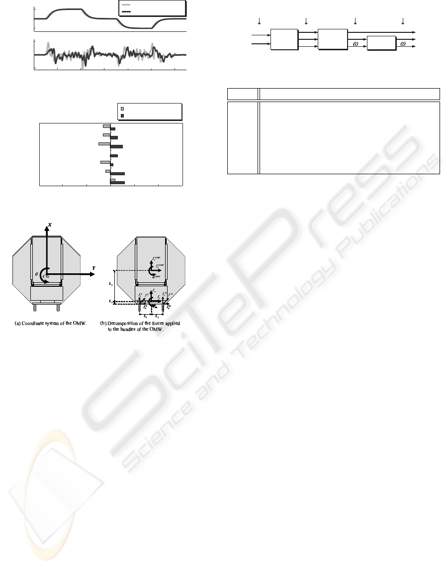
Jerk was evaluated by differentiating the output of
the encoders of OMW’s motors. Experimental results
are shown in Fig. 2. v
x
is the reference velocity, j
omw
x
ICINCO 2006 - INTELLIGENT CONTROL SYSTEMS AND OPTIMIZATION
68
0 2 4 6 8 10 12
1st-order controller
2nd-order controller
-5
0
5
jx [
m/s
]
3
omw
0 2 4 6 8 10 12
-1
0
1
vx [
m/s
]
jerk
velocity
time t [s]
Figure 2: Experimental result of jerk.
-2 -1 0 1 2
point
1st-order controller
2nd-order controller
3-3
swing
feeling
security
comfort
stability
reliability
ride quality
Figure 3: Questionnaire result of x-axis.
Figure 4: Working force.
shows the actual jerk that was calculated by using the
encoders output.
In addition, as riding comfort is something that de-
pends on the subjective judgement of the OMW’s oc-
cupant, riding comfort was evaluated by using Se-
mantic Differential (SD) method. The mean value of
the results obtained in each item of the SD question-
naire are shown in Fig. 3 for x direction. It is possible
to see that the values obtained by the second order
controller are much better than that obtained by the
first order controller. Then a second order controller
will be used as power assist controller because it can
improve riding comfort.
3.2 Direction Estimator of
Navigation for Input Force
When the user tries to rotate OMW around its grav-
ity center, OMW begins to slide and the radius of ro-
tation sometimes becomes very big. Then, rotation
around the center is very difficult (Kitagawa et al.,
2004). A survey was conducted among various at-
tendants trying to discover some relationships in the
way they realized forwards-backwards, lateral and ro-
6axis force
sensor
2nd-order
controller
f
R
directional
reasoning
f
L
f
x
f
y
m
v
x
v
y
d
d
v
y
d
Sensor
input
Sensor
output
Transfer
to velocity
Command input by
direction estimator
Figure 5: Block diagram of power assist system.
Table 1: Fuzzy reasoning rules.
Rule Antecedent Consequent
1 v
y
> 0 and ω < 0, v
d
y
> 0 (Right Slide)
2 v
y
< 0 and ω > 0, v
d
y
< 0 (Left Slide)
3 v
y
≈ 0 and ω ≈ 0, v
d
y
≈ 0 (Not Slide)
4 v
y
≥ 0 and ω > 0, ω
d
> 0 (CCW Turn)
5 v
y
≤ 0 and ω < 0, ω
d
< 0 (CW Turn)
6 v
y
≈ 0 and ω ≈ 0, ω
d
≈ 0 (Not Turn)
tational movements. The goal of the survey was to
find general rules that related the three mentioned mo-
tions. Even when it was impossible to find general
rules that explained all cases, a relationship was found
between lateral and rotational movements. These re-
lationships were used as the base for constructing a
fuzzy reasoning system (MathWorks, 2002)-(Harris
et al., 1993) that helped to improve the operability
of the OMW. These rules, in which just lateral mo-
tion and rotational motion are considered, are shown
in Table 1. The block diagram of the system that con-
siders power assist and fuzzy reasoning is shown in
Fig. 5.
In order to establish the rules of direction inference,
first, the force applied to the grips of the force sensor
are changed to the center of OMW, as shown in Fig. 4.
Note that the input of the direction estimator is veloc-
ity V
omw
, not force F . It may seem more reasonable
to use F for the estimation of the attendant’s inten-
tion, however, it is very difficult to derive transform
equations from F , because of an effect of vibration of
input force or noise. v
x
is not included since forward
and backward motion can be realized without direc-
tion estimation. Features of slide motion is expressed
by Rules 1 and 2 in Table 1, and that of rotation by
Rules 4 and 5. Rules 3 and 6 are added not to gener-
ate the reference velocity when input velocity is zero.
The reason of these rules is shown in Table 1. Ta-
ble 1 is described in detail in (Kitagawa et al., 2004),
and hence the explanation is omitted due to the paper
space.
Figure 6 shows the graph of membership functions
of the first rule. The membership function of the an-
tecedent of 1, 2, 4 and 5 is
µ
name
= tan
−1
{a
name
(β
i
− b
name
)} /π +0.5, (2)
where β
i
is input (β
1
= v
y
, β
2
= ω) and a
name
and
b
name
are tuning parameters. ‘name’ is replaced
by the name of each membership function. The
first letter of ‘name’ of antecedents indicates sensor
output(v
d
y
:Y, ω
d
:O), the second letter indicates sign
ENHANCEMENT OF MANEUVERABILITY OF A POWER ASSIST OMNI-DIRECTIONAL WHEELCHAIR BY
APPLICATION OF NEURO-FUZZY CONTROL
69
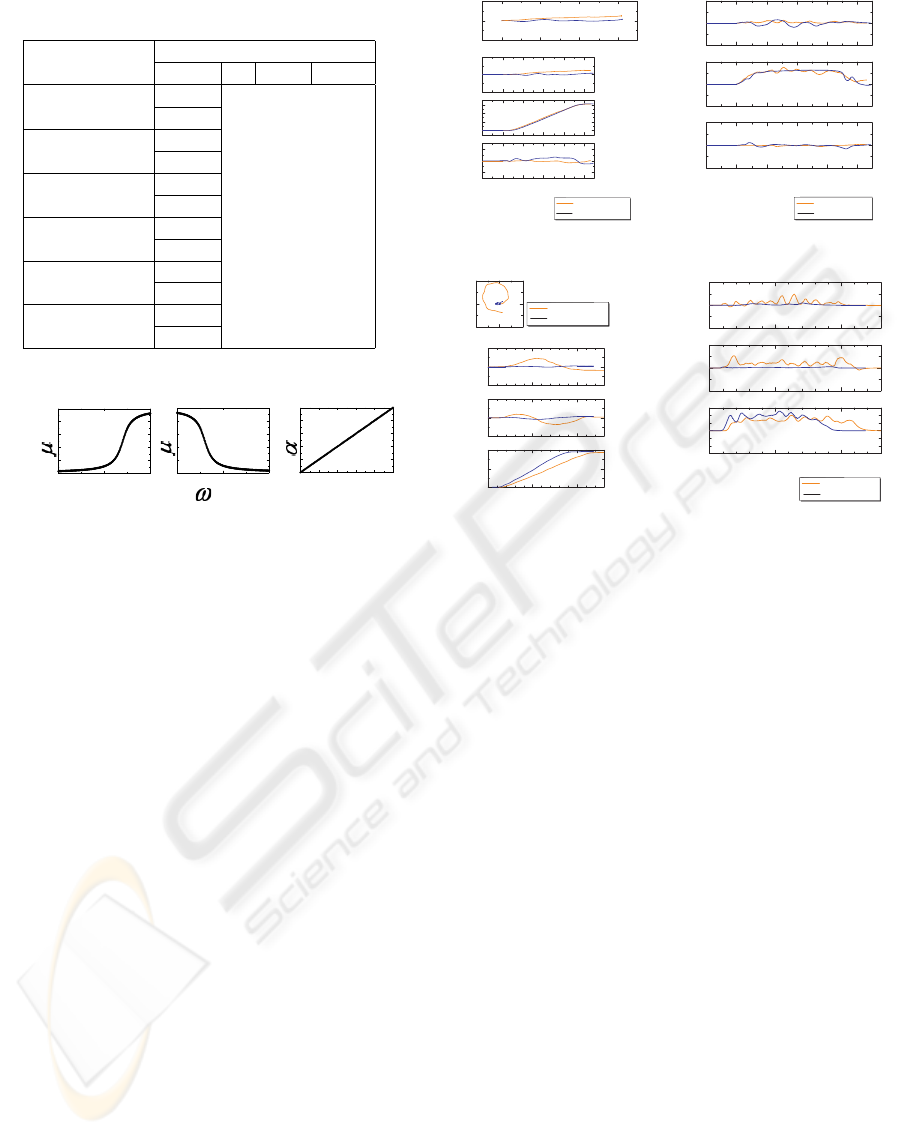
Table 2: Parameters of menbership functions.
Rule Number
Antecedent
name a b c
1
YPS 7 0.3 -
ONS 7 -0.3 -
2
YNS 7 -0.3 -
OPS 7 0.3 -
3
YZS - - 1000
OZS - - 1000
4
YPT 7 0.3 -
OPT 7 0.3 -
5
YNT 7 -0.3 -
ONT 7 -0.3 -
6
YZT - - 1000
OZT - - 1000
-1 0 1
0
1
-1 0 1
0
1
0
1
0
1
[rad/s]
Antecedent 1
ConsequentAntecedent 2
Rule 1
YPS
ONS
vy [m/s]
yRS
RS
Figure 6: Membership functions of rule 1.
(Positive:P, Negative:N, Zero:Z), and the third letter
indicates the realized motion (Slide:S, Turn:T).
The membership function of the antecedent of 3
and 6 is
µ
name
= exp(−c
name
· β
2
i
), (3)
where c
name
is a tuning parameter.
3.3 Experimental Results
In order to verify the effectiveness of the control sys-
tem, laboratory experiments were conducted. The re-
sults shown correspond to a first order controller. Pa-
rameters of the membership function of Fig. 6 are
shown in Table 2. These parameters are given by trial
and error method. The details are described in the for-
mer paper (Kitagawa et al., 2004).
The trajectory and velocity v
d
omw
of slide motion
to right are shown in Fig. 7 and Fig. 8, respectively.
As seen in the trajectory of v
d
y
, vibration of the ve-
locity was reduced. The trajectory and velocity v
d
omw
of rotation around its center in counter-clockwise are
shown in Fig. 9 and Fig. 10, respectively. As seen
in Fig. 9, the rotation around its center was realized
by using the direction estimator. The effectiveness of
the direction estimator is shown especially in case of
rotation. In this case, the gain of the controller for
the velocity in the direction X, Vx, was reduced to
very small value in order to tes the goodness of the
approach.
0 1 2 3
-1
0
1
y
G
[m]
x
G
[m]
0 2 4 6 8 10
-1
0
1
x
G
[m]
0 2 4 6 8 10
0
1
2
3
y
G
[m]
0 2 4 6 8 10
-10
0
10
q
G
[deg]
Time [s]
No-reasoned
Reasoned
Figure 7: Trajectory of right
slide.
0 2 4 6 8 10
-1
0
1
v
y
d
[m/s]
0 2 4 6 8 10
-1
0
1
w
d
[rad/s]
Time[s]
0 2 4 6 8 10
-1
0
1
v
x
d
[m/s]
No-reasoned
Reasoned
Figure 8: Velocity v
d
omw
of right slide.
0 5 10
-1
0
1
x
G
[m]
0 5 10
-1
0
1
y
G
[m]
0 5 10
0
200
400
q
G
[deg]
Time[s]
-0.5 0 0.5
-0.5
0
0.5
y
G
[m]
x
G
[m]
No-reasoned
Reasoned
Trajectory of the
CG of OMW
Figure 9: Trajectory of rota-
tion (CCW).
0 5 10
-1
0
1
v
y
d
[m/s]
0 5 10
-1.5
0
1.5
w
d
[rad/s]
Time[s]
0 5 10
-1
0
1
v
x
d
[m/s]
No-reasoned
Reasoned
Figure 10: Velocity v
d
omw
of rotation (CCW).
4 TUNING OF FUZZY SYSTEM
Figure 11 shows attendant’s intention representing di-
rection to make OMW move using v
y
and ω added by
attendant. In the present fuzzy parameters given by
the previous section, the attendant such as examinee
1 can operate OMW well. On the other hand, the
attendant such as examinee 2 wants to make OMW
move towards right in the region of v
y
> 0 and ω ≈
0.
Then, when fuzzy membership function is fixed
based on examinee 1 for all examinees, the attendant
with having the tendency like examinee 2 feels the dif-
ficulty to operate OMW. Therefore, it is necessary to
adjust the parameters of fuzzy membership functions
according to the driving characteristics of individual
attendants.
The fuzzy system must be tuned to respond to the
particular characteristics of each attendant. As the
tuning by trial and error is a time consuming and cer-
tainly not optimal, the tuning of the fuzzy system by
using a neuro-fuzzy system is proposed in this pa-
per. In the literature there are many neuro-fuzzy sys-
tems. ANFIS(Adaptive-Network-Based Fuzzy Infer-
ence System) (Jang, 1993) was chosen for this re-
search. The details of the implementation of ANFIS
are not presented here. For further information refer
to (Jang, 1993).
According to the rules shown in Table 1, the range
ICINCO 2006 - INTELLIGENT CONTROL SYSTEMS AND OPTIMIZATION
70
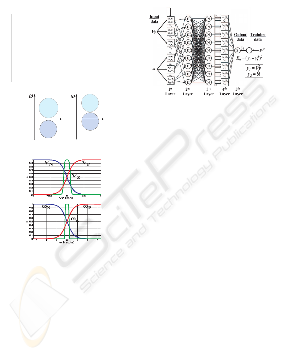
Table 3: Fuzzy rules for ANFIS.
R Antecedent Consequent
1 If V
N
and ω
N
, y
1
= A
1
× V
N
+ B
1
× ω
N
+ C
1
2 If V
Z
and ω
N
, y
2
= A
2
× V
Z
+ B
2
× ω
N
+ C
2
3 If V
P
and ω
N
, y
3
= A
3
× V
P
+ B
3
× ω
N
+ C
3
4 If V
N
and ω
Z
, y
4
= A
4
× V
N
+ B
4
× ω
Z
+ C
4
5 If V
Z
and ω
Z
, y
5
= A
5
× V
Z
+ B
5
× ω
Z
+ C
5
6 If V
P
and ω
Z
, y
6
= A
6
× V
P
+ B
6
× ω
Z
+ C
6
7 If V
N
and ω
P
, y
7
= A
7
× V
N
+ B
7
× ω
P
+ C
7
8 If V
Z
and ω
P
, y
8
= A
8
× V
Z
+ B
8
× ω
P
+ C
8
9 If V
P
and ω
P
, y
9
= A
9
× V
P
+ B
9
× ω
P
+ C
9
right
slide
ccw
turn
vy
right
slide
ccw
turn
examinee 1
examinee 2
vy
Figure 11: Attendant’s intention.
Figure 12: Partition of the ranges of V
y
and ω.
of V
y
and ω is divided in three Membership Functions
(MF), Negative (V
N
and ω
N
), Zero (V
Z
and ω
Z
) and
Positive (V
P
and ω
P
), as shown in Fig. 12. The func-
tions used for the partitions of the range of V
y
and ω,
shown in Fig. 12, are called the dsigmoidal (Math-
Works, 2002) functions, and are defined as the differ-
ence of two sigmoidal functions. That is, if Eq. (4) is
a sigmoidal function, with parameters a and c,
f(x, a, c) =
1
1 + e
−a(x−c)
(4)
A dsigmoidal function can be defined as
f(x, a
1
, c
1
)−f (x, a
2
, c
2
)=f(x, [a
1
, c
1
, a
2
, c
2
]) (5)
As there are 6 membership functions, and each with
4 parameters, there must be 24 parameters that are
denoted as (a
1
...a
12
), (c
1
...c
12
).
Then, as there are three partitions in each variable,
the total number of rules must be 3 × 3 = 9 rules,
Figure 13: ANFIS system.
which are shown in Table 3. The odd rules correspond
to those shown in Table 1, while the even rules are
used for completeness. In the rules shown in Table 3
the consequents are a function of the inputs because
a Takagi-Sugeno-Kang (TSK) (Takagi and Sugeno,
1985) system is being used, instead of the Mamdani
(Mamdani and Assilian, 1985) system used for the
rules of Table 1. The coefficients of the consequents
are denoted by (A
1
...A
9
), (B
1
...B
9
) and (C
1
...C
9
), as
shown in Table 3. The ANFIS equivalent of this sys-
tem is shown in Fig. 13. ANFIS has 5 layers:
• 1
st
Layer: Here the inputs Vy and ω are subjected
to the action of the membership functions of Fig.
12, that are represented by its parameters (a
1
... a
12
)
and (c
1
... c
12
).
• 2
nd
Layer: In the 2
nd
Layer the fuzzy rules shown
in Table 3 are constracted. As the antencedents are
jointed by a logic ”AND”, this relationship is math-
ematically obtained by the product (Π) of the two
antecedents. The output of each node represents
the firing strength of a rule, that is represented by
ω
i
(i = 1 ... 9).
• 3
rd
Layer: This is a normalization layer, where the
ratio of the i
th
rules’ firing strength to the sum of
all rules firing strength is calculated.
• 4
th
Layer: Here the normalized firing strength that
comes from the 3
rd
Layer is multiplied by the out-
put functions of the fuzzy reasoning system.
• 5
th
Layer: The overall output of the system is com-
puted as the sum of all the incoming signals.
For using ANFIS, the structure of the block labeled
as ”directional reasoning” in Fig. 5 is shown in Fig.
14. It is clear that two fuzzy systems, one for Vy, and
the other for ω are used.
For the off-line training of ANFIS system of the
OMW, the following approach was followed:
ENHANCEMENT OF MANEUVERABILITY OF A POWER ASSIST OMNI-DIRECTIONAL WHEELCHAIR BY
APPLICATION OF NEURO-FUZZY CONTROL
71
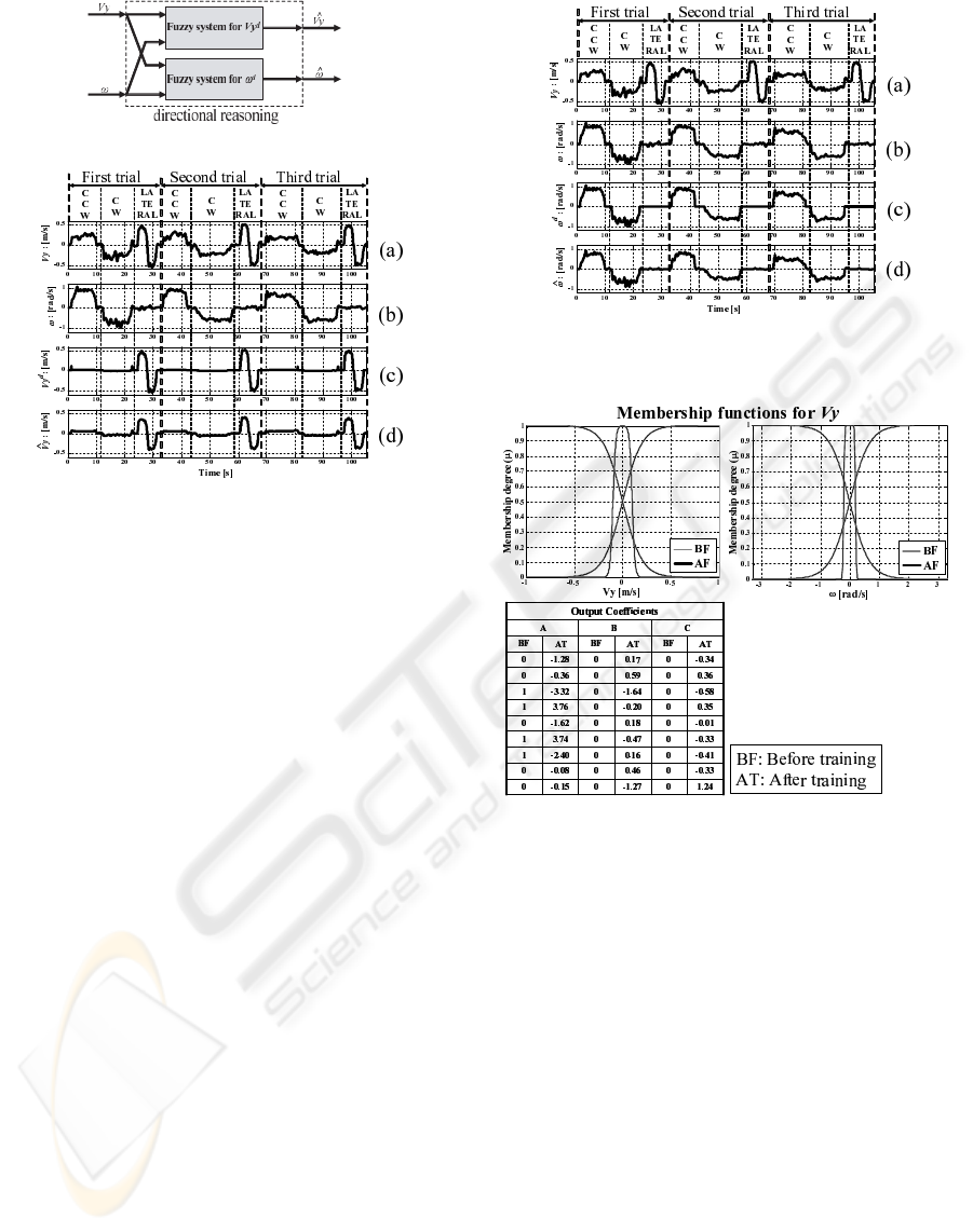
Figure 14: Contents of the block directional reasoning.
Figure 15: Input data and results of teaching for the case of
lateral movement((a)-(b): input data, (c): teaching data and
(d): estimated output data).
(i) An attendant is asked to conduct five kind
of movements composed of: (1) forward and
backward movement, (2) lateral movement, (3)
counter-clockwise (CCW) rotation, (4) clock-
wise (CW) rotation and (5) forwards and back-
wards diagonal movement, for five times. For
taking this data just power assistance is used.
Three groups of data will be used for the training
of ANFIS and the remaining two for the testing
of the obtained results.
(ii) ANFIS is trained and tested by using a simula-
tion program developed in Matlab. The validity
of this simulator has been tested by comparing
the results obtained from simulation and experi-
ments.
(iii) The obtained parameters are saved in the com-
puter of the OMW and the system is tested by
experiments.
In this paper, the simulation results will correspond
to one attendant called ”Attendant 1”. Fig. 15 shows
the input data (a)-(b), the teaching data (c), and the
estimated output data (d) after the training by ANFIS
for ”Attendant 1” for the case of lateral movement.
In Fig. 16 the same information is shown for the case
of rotational movement. The teaching data was con-
structed following the logic of Table 3. The ANFIS
systems was trained by using the input and teaching
data shown in Fig. 15 and Fig. 16. The total error in
each epoch was calculated as:
J = Σ
N
n=1
E
n
, (6)
Figure 16: Input data and results of teaching for the case of
rotational movement((a)-(b): input data, (c): teaching data
and (d): estimated output data).
Figure 17: Results of training of Vy system.
where,
E
n
= (y
i
(n) − y
d
i
(n))
2
, (7)
with n being the n
th
data and N the total number of
data used for the training. Tuning is performed by
minimizing the output error of the NN used in combi-
nation with the fuzzy inference system. For achieving
this goal, the NN is trained by using a hybrid method
that combines least squares and the Backpropagation
algorithm (BP law). This method is thus thought to be
an effective method for tuning the parameters of the
OMW’s fuzzy inference system. In the case shown in
Fig. 15 and Fig. 16, N = 8530. According to the re-
sults obtained from different trials, it has been found
that, in order not to lose the generality, the miminum
total error allowed should be around 0.05 for both sys-
tems. The time needed for the training of the ANFIS
system is around 1 [min], and the convergence to the
desired values of error is reached after 20 epochs. The
results of the training are shown in Fig. 17 and Fig.
18. It is possible to note that the shape of the member-
ICINCO 2006 - INTELLIGENT CONTROL SYSTEMS AND OPTIMIZATION
72
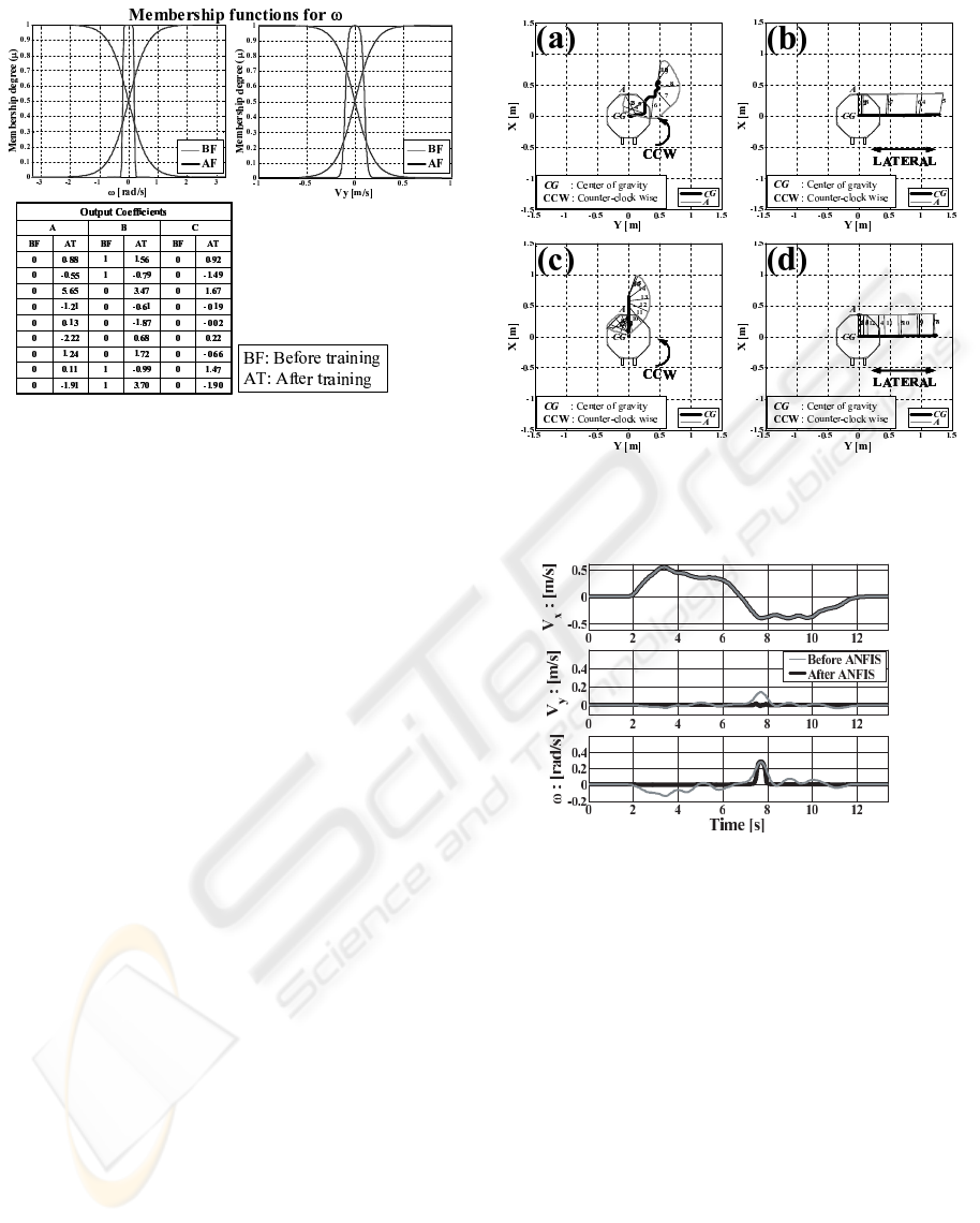
Figure 18: Results of training of ω system.
ship functions almost does not change for any of the
systems, Vy or ω. However, the change in the output
function is easily seen. By the change in the output
functions the system adjust to the input data of the
attendant.
Results for one case of testing data, that the training
of ANFIS did not include, are shown in Fig. 19. The
trajectory of the OMW when ”Attendant 1” rotates
the OMW in CCW direction and moves the OMW in
lateral direction by using just power assist, are shown
in Fig. 19 (a) and Fig. 19 (b). It is possible to see that
CCW rotation is influenced by the lateral velocity and
the velocity in direction X. The lateral movement is
almost a perfect horizontal line. Fig. 19 (c) and Fig.
19 (d) show the result for CCW rotation and lateral
movement after ANFIS was applied. As lateral move-
ment is almost the same as desired, from now the dis-
cussion will be centered in the rotational movement in
CCW direction. As expected from the results shown
in Fig. 16 the rotational movement in CCW direction
has been improved by reduction of the lateral velocity.
However, as in this case the gain of the controller for
Vx has not been reduced as it happened in the cases
shown in Fig. 7 - Fig. 10, there is some displacement
in direction X. Just reducing the gain of the controller
in the direction X, as before, could be a good solution.
However, it will influence the movement of the OMW
when the attendant wants to easily move forwards or
backwards. Then, some relationship must be estab-
lished between the different movements studied here:
rotation, lateral and forwards and backwards, that al-
lows to reduce the velocity in direction X, Vx, when
rotating and let it pass almost untouched when mov-
ing forwards or backwards. The influence of Vx in the
lateral movement is almost irrelevant, and for that rea-
son is not considered any action in the case of lateral
movement.
After the reasoning system has been trained with
Figure 19: Trajectory of the OMW in CCW rotation and lat-
eral movement. (a) and (b) show the cases in which power
assist only is used, and (c) and (d) the result by ANFIS.
Figure 20: Vx, Vy and ω for a case of forwards and back-
wards movement of the OMW, by”Attendant 1”.
ANFIS, in the case when the movement of the OMW
is not a rotational movement, ω is reduced according
to the training described in previous paragraphs. It
happens in the case of lateral movement and in the
case of forwards and backwards movement too. By
studying the value of ω when ”Attendant 1” moves
the OMW forwards and backwards, it has been found
that it is always less than 0.3 [rad/s]. Fig. 20 shows
one case of forwards and backwards movement. Es-
tablishing a rule in which for all the cases in which
ω is less than 0.3 [rad/s] was considered in principle.
However it will ignore cases like the one shown in
Fig. 21.
In Fig. 21 it is possible to see that for a rotational
movement the value of ω is greater than 0.2 [rad/s]
and it happens in all the cases studied for ”Attendant
1”. Then a rule is established such as Vx must be mul-
tiplied by a Reducing Multiplicative Factor (RMF) if
the value of ω is greater than 0.2 [rad/s]. The value
ENHANCEMENT OF MANEUVERABILITY OF A POWER ASSIST OMNI-DIRECTIONAL WHEELCHAIR BY
APPLICATION OF NEURO-FUZZY CONTROL
73
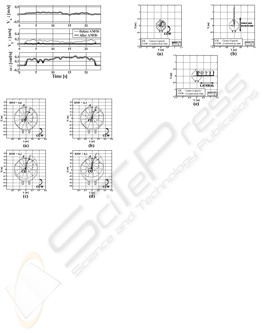
Figure 21: Vx, Vy and ω for a case of rotational movement
of the OMW, by ”Attendant 1”.
Figure 22: Trajectory of the OMW in CCW rotation when
the Reduction Multiplicative Factor (RMF) is (a) RMF = 0,
(b) RMF = 0.1, (c) RMF = 0.2 and (d) RMF = 0.3.
of RMF is decided by trial and error, by trying mul-
tiples of 0.1. Fig. 22 shows the cases in which RMF
= 0, 0.1, 0.2, 0.3. As it is seen there, a value greater
than 0.2 is not so good. Then it is decided that the
range of variation of RMF must be [0 ∼ 0.2], and the
mean value, 0.1, is chosen for this research. Results
the reduction of Vx are shown in Fig. 23 for CCW ro-
tation, lateral movement and forwards and backwards
movement, when RMF = 0.1. It is possible to see that
operability has been improved by the application of
the fuzzy reasoning system tuned by ANFIS. In this
paper, the threshold of ω is 0.2 [rad/s] and RMF = 0.1.
But these values may change by attendant. Therefore,
it is a future problem to generalize how to determine
these values such as RMF and threshold.
5 CONCLUSIONS
A power assist system for omni-directional wheel-
chairs considering both attendant’s manipulability
Figure 23: Improvement of the trajectory of the OMW in
CCW rotation when Vx is multiplied by a factor 0.1.
and rider’s comfort has been developed. The refer-
ence velocity of the omni-directional wheelchair was
derived from attendant’s input force. Operability of
rotation was improved greatly by using the fuzzy di-
rection estimator. The membership functions of the
fuzzy systems are tuned using attendant’s input data
by applying a neuro-fuzzy system (ANFIS).
ACKNOWLEDGEMENTS
This work was partially supported by The 21
st
Cen-
tury COE (Center of Excellence) Program ”Intelligent
Human Sensing”
REFERENCES
FrankMobilitySystems (2002). Frank mobility systems inc.
In http://www.frankmobility.com/.
Harris, C. J. et al. (1993). Intelligent control. World Scien-
tific.
Jang, J. (1993). Anfis: Adaptive-network-based fuzzy infer-
ence system. In IEEE Transactions on Systems, Man,
and Cybernetics, Vol. 23(3), pp. 665-685.
Kitagawa, H. et al. (2001). Semi-autonomous obstacle
avoidance of omnidirectional wheelchair by joystick
impedance control. In Proc. IEEE/RSJ Int. Symp. on
Intelligent Robots and Systems, pp. 2148-2153.
Kitagawa, H. et al. (2002). Motion control of omnidi-
rectional wheelchair considering patient comfort. In
Proc. IFAC World Congress, T-Tu-E20.
Kitagawa, H. et al. (2004). Fuzzy power assist control
system for omni-directional transport wheelchair. In
Proc. IEEE/RSJ Int. Conf. on Intelligent Robots and
SystemsC1580-1585.
ICINCO 2006 - INTELLIGENT CONTROL SYSTEMS AND OPTIMIZATION
74

Lin, C. T. and Lee, C. S. G. (1991). Neural-network-based
fuzzy logic control and decision system. In IEEE
Trans. on Computers, Vol. 40(12), pp. 1321-1336.
Maeda, H. et al. (2000). Development of omni-directional
cart with power assist system (in japanese). In Proc.
18th Annual Conf. of Robotics Society of Japan, 15,
pp.1155-1156.
Mamdani, E. H. and Assilian, S. (1985). An experiment in
linguistic synthesis with a fuzzy logic controller. In
International Journal of Man-Machine Studies, Vol.
7(1), pp. 1-13.
MathWorks (2002). Fuzzy logic toolbox user’s guide ver-
sion 2, pp. 3-18. The Matworks Inc.
Seki, H. et al. (2005). Novel driving control of power as-
sisted wheelchair based on minimum jerk trajectory.
In IEEJ Trans. EIS Vol. 125(7) (in Japanese), pp. 1133
- 1139.
Takagi, T. and Sugeno, M. (1985). Fuzzy identification of
systems and its applications to modeling and control.
In IEEE Transactions on Systems, Man and Cybernet-
ics, Vol. 15(1), pp. 116 - 132.
Terashima, K. et al. (2004). Frequency shape control of
omni-directional wheelchair to increase user’s com-
fort. In Proceedings of the 2004 IEEE International
Conference on Robotics and Automation (ICRA), pp.
3119-3124.
Wada, M. and Asada, H. (1999). Design and control of a
variable footprint mechanism for holonomic omnidi-
rectional vehicles and its application to wheelchairs.
In Proc. IEEE Trans. Robot. Automat, 15, pp. 978-
989.
West, M. and Asada, H. (1992). Design of a holonomic om-
nidirectional vehicle. In Proc. IEEE Int. Conf. Robot.
Automat., pp. 97-103.
ENHANCEMENT OF MANEUVERABILITY OF A POWER ASSIST OMNI-DIRECTIONAL WHEELCHAIR BY
APPLICATION OF NEURO-FUZZY CONTROL
75
