
VERIFICATION AND VALIDATION OF THE REAL TIME
SYSTEM IN THE RADAR SENSOR
Naibin Li
Chinese national heavy Truck Corp. Technology Development center
165 Ying Xong Shan Road, Jinan, Shandong, China 250002
Keywords: verification, validation, UPPAAL.
Abstract: This paper presents the modeling, simulation and verif
ication of the embedded real time system for the
memory interface system based on the tool UPPAAl. The real time system of the memory interface in the
radar sensor is the arbiter as the kernel of the non-preemptive, fix cycle, round-robin schedule controls and
schedules four input buffers, the five output buffers and two integrators working synchronously to share the
system resource. We construct accurately dynamic model as the networks of timed automata with rigorous
logic and real timed abstraction of this real time system, this hybrid system with discrete and continuous
state change consists of six process templates and 20 concurrent processes. We simulate and verify the
entire system to detect potential fault in order to guarantee the reliability of the design of the real time
system.
1 INTRODUCTION
The real time system requires the high availability,
reliability and the safety, fault tolerance capacity.
Possible faults must be detected and prevented. the
advanced software UPPAAL models, simulates and
verifies the real time system to detect effectively
possible failures, which bases on the timed-automata
and consists of the graphical user interface of the
simulation and the model-checker engine, we model
dynamically the real time system of the memory
interface based on rigorous constrain of logic and
real time and simulate exhaustively all of dynamic
system behavior, using symbolic reachability
analysis technology verifies automatically safety
properties based on the temporal logic CTL to check
exhaustively all of dynamic system behavior, which
detects possible faults of the system including the
underflow of the input buffers, the overflow of the
output buffers, the failure of the schedule algorithm
in order to guarantee the correctness of the design.
Timed Automata
The timed automaton have been successfully used in
t
he verification becoming standard model of real
time systems, which precisely represent finite-state
timed behavior with real continuous value clock
variable x, y, z etc as rigorous constraint and
equipped with simple logic variable constrain.
Definition:
A is a tuple (L, l0, C, E, clocks, Label, guard, I )
• L is t
he set of location denoted finite state.
• l
0
is the initial location representing initial state.
• C is m
any clock variables representing real time
value and non-negative.
• E ⊆ L×L t
he set of the edges. If ( l, l’ ) ∈E
then writing lÆl’
• cl
ocks: E→2
c
, which assign clocks for each edge.
• gua
rd: E→ϕ(C), the set of constraint assigned each
edge.
• I: L→ϕ(C
), the invariant assigned to each location.
2 THE REAL TIME SYSTEM
The memory interface system in the newest Terma
sensor implements to combine and integrate two
different of radar signals received with a short time
delay from the same target area in order to increase
the power of the output signals, the buffer 1, 2
receives two radar signals and transfers to SDRAM
through the arbiter.
421
Li N. (2005).
VERIFICATION AND VALIDATION OF THE REAL TIME SYSTEM IN THE RADAR SENSOR.
In Proceedings of the Seventh International Conference on Enterprise Information Systems, pages 421-424
DOI: 10.5220/0002544804210424
Copyright
c
SciTePress
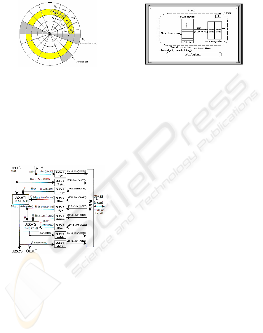
Figure 1: The sliding window of the radar echoes
sum
i,r
= e
i,r
+ sum
i-1,r
– e
i-m,r
i: the angle of cell. r: the range cell
m: the number of the sweep.
The sweep integration is calculated a sum over
related cells from multiple sweeps of received radar
echoes for each signal by two integrators in order to
get size of the target and remove the noise. SDRAM
stored radar signals and the result of integration
connects the two integrators via nine FIFO buffers
having different capacities and one scheduling
arbiter, which forms continuous data stream in the
bus to share the system resource.
Figure 2: The memory interface system
The structure of th
e buffer
FIFO buffer consists of two register, the capacity of
the Register is 256bit. The flag of the input buffer is
1, data is full, data can be read from the register
when the arbiter allow. It is 0 denoted the register is
empty, data can be move to the register form the
input buffer. Data is empty when the flag of the
output buffer is 1,Data can be written to the register
when the arbiter allow. Data is full when it is 0. Data
can not be move to the output buffer
Figure 3: The structure of the buffer
3 THE POTENTIAL FAILURES AND
THE SOLUTIONS
3.1 The problem of the overflow
The system receives the signals of 8bit and writes to
the input buffer at 10ns continuously, then moves
data of 32bit to the register at 10ns when data of
buffer is at lease 32 bit. Data of 256bit is read from
the register to the memory SDRAM when flag is 1
and the schedule algorithm allows. The system
refresh the memory for 100ns every 15.625µs,
which do not allow any access during this time, the
register have not transferred data. But the input
buffers still receive radar signals to form a big
accumulate of data, it is possible that exceeds the
maximal capacity of the buffer, which happens
overflow to lead to the fault.
Therefore, we construct the Ibwrite and Ibmove
automata based on rigorous, dynamic behavior
abstraction of writing data to the buffer and moving
data to the register by timed automata to check
properties data of the buffer < the maximal capacity
of the buffer and deadlock, which detects failure of
the overflow.
3.2 The problem of the underflow
The system reads data from the memory and writes
to the register, then move to the output buffer by the
arbiter controls, there is a delay time from data is
read from the memory to move to the output buffer.
The output buffer will happen the underflow if data
can not be received on time.
Therefore, we construct the timed automata
Oboutput and the Obmove based on rigorous,
dynamic behavior abstraction of the system moves
data to register and writes to the output buffer to
check the properties data of the buffer > 0 and
deadlock for by the verification, which detects
failure of the overflow.
ICEIS 2005 - INFORMATION SYSTEMS ANALYSIS AND SPECIFICATION
422
3.3 The problem schedule algorithm
The schedule algorithm is the non-preemptive, fix
cycle, round-robin scheduling algorithm, the arbiter
as the system kernel controls and schedules various
buffer to allocate shared resource respectively,
which is cyclic executive to form the loop.
Therefore, we construct the timed automata arbiter
based on rigorous, dynamic behavior abstraction of
the schedule arbiter to detect possible failure of
schedule algorithm.
System variables are set by scripting commands or
are determined by the information your enter when
you set up a Dial-Up Networking connection.
System variables are read-only, which means they
cannot be changed within the script.
4 THE FORMALIZATION OF THE
SYSTEM
4.1 Overview of the model for the
memory interface system
The model of memory interface system consists of
the six timed automata as shown figure 4. Each input
buffer is composed of a Ibmove and Ibmove
automata respectively, Each output buffer is
composed of a Obmove and Obwrite automata by
respectively, which are automata networks of nine
buffers, the arbiter and the refreshing memory.
Figure 4: The networks model of the timed automata
The system produces concurrent 20 processes to
work synchronously by the schedule arbiter controls
at same increasing local time, which implements
transfer of data forming continuous data stream to
share the resource of the bus. Each process forms
different loop respectively. The processes
communicate and synchronize by global variable
and local clock
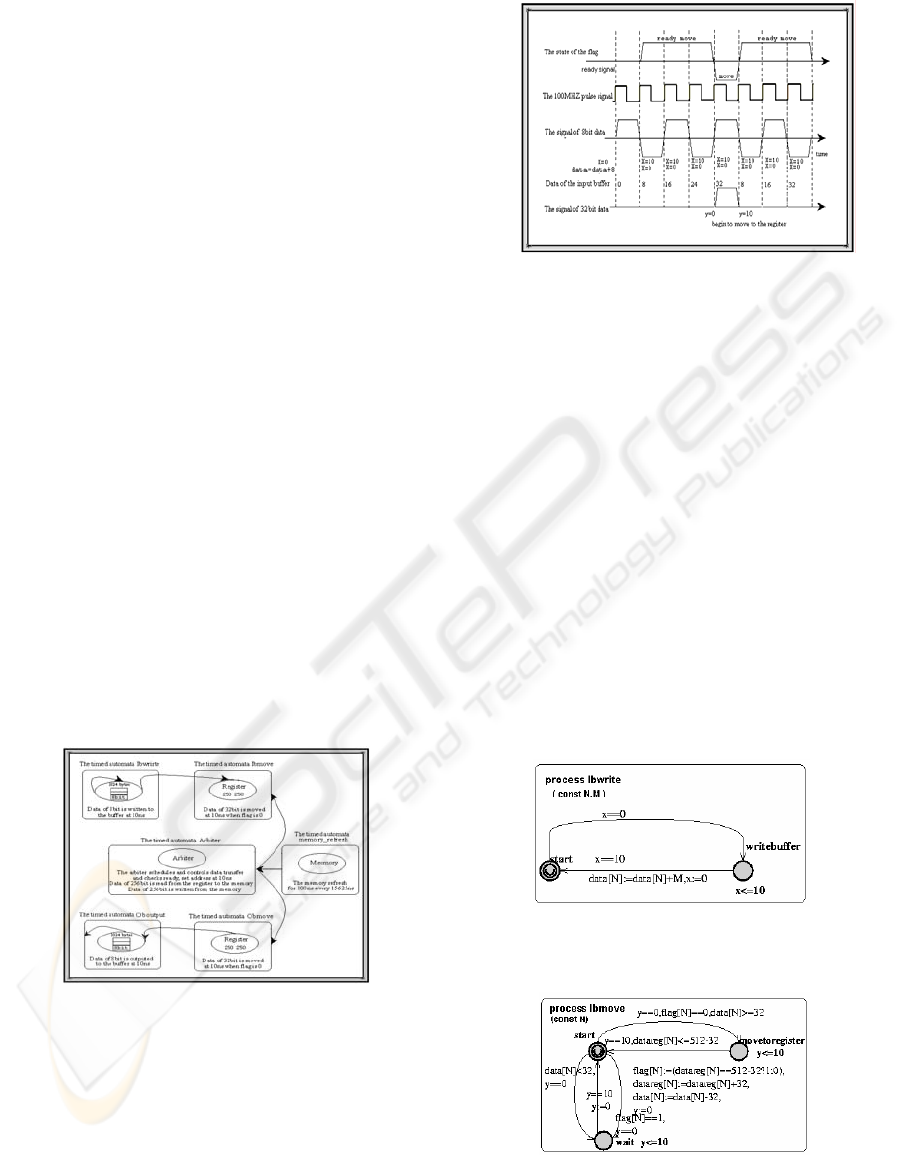
Figure 5: The working evolution in the input buffer over
local time
The system receives the signals of 8bit data at 10ns to the
input buffer, then resets x is 10, which forms continuous
loop. The signals of 32bit data is written to register when
flag is 0 and data in the buffer is at least 32bit.
The system uses the local clock variable x, y, z.
x: the time of beginning to write the 8bit data to the
input buffer
y: the time of beginning to write the 32bit data from
the buffer to the register. the delay time of y
delays x is 40ns.
z: the time of beginning to refresh memory is same
beginning with x.
4.2 The networks of the timed
automata
The timed automata Ibwrite
The behavior abstraction is that writes data to the
input buffer
The timed automata Ibmove
The behavior abstraction is that move data to the
register
The timed automata Obmove
The behavior abstraction is that moves data to the
output buffer
VERIFICATION AND VALIDATION OF THE REAL TIME SYSTEM IN THE RADAR SENSOR
423
The timed automata Output
The behavior abstraction is that writes data to the
input buffer
The timed automata memory_refresh
The behavior abstraction is that outputs data to the
output buffer.
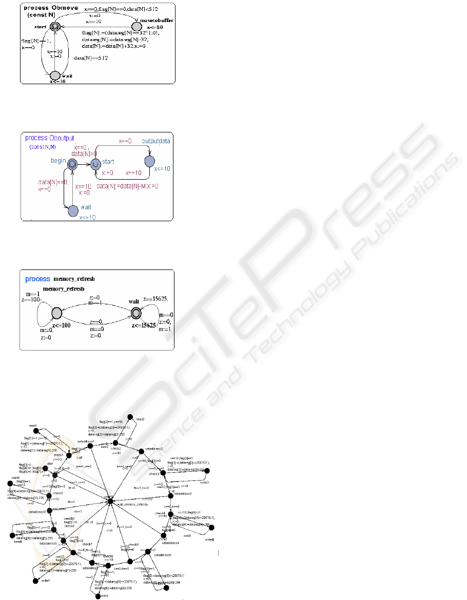
The timed automata Arbiter
The system kernel is the non-preemptive, fix cycle,
round-robin scheduling algorithm. The behavior
abstraction is the arbiter controls and schedules the
work of each component to share the bus resource.
N: the number of the buffer.
M: the amount bits of output for the output buffer.
data[N]: the variable of data of the N buffer.
Datareg[N]: the variable of data of the register for N
buffer.
flag[N]:the flag mark if the register is empty and data can
be read and write.
m: the flag mark the memory is refreshing when it is 1,
the arbiter stop work.
5 THE IMPLEMENTATION OF
THE VERIFICATION
We verify relevant properties for every buffer and
the arbiter.
The safety properties :
A[] no deadlock
This is the property checking deadlock., the
deadlock never happen.
A[] P1.x==0 imply data[1]<8192
A[] E1.x==0 imply data[1]<4096
A[] R1.x==0 imply data[1]<16384
This is the properties checking if the input
buffer 1, 8, 9happen overflow.
A[] B3.start imply data[3]>0
A[] Q3.start imply data[3]>0
The model checking covers all of the possible
system behavior , which is a extremely large state
space exploration with huge memory consumption.
All property are satisfied by the verification, which
did not detect any failure happens, therefore, the
system design is the reliable and safety, which is
confirmed by the specialist in the term company.
6 CONCLUSION
The time critical system requires high performance.
In order to detect potential fault of the interface
system, guaranteeing the reliability and the safety.
We have constructed the dynamic model of the
memory interface system and verified relevant,
reachability properties to detect the possible failures
of the overflow, underflow of the buffer and
scheduling algorithm by the software Uppaal.
Therefore, we comfirm the satfety and reliability of
the interface memory system design.
REFERENCES
Kim G.Larsen, Paul Pettersson and Wang Yi,UPPAAL
in a Nutshell. In Springer International Journal of
Software Tools for Technology Transfer 1(1+2), 1997
ICEIS 2005 - INFORMATION SYSTEMS ANALYSIS AND SPECIFICATION
424
