
DEFINITION OF BUSINESS PROCESS INTEGRATION
OPERATORS FOR GENERALIZATION
Georg Grossmann, Yikai Ren, Michael Schrefl, Markus Stumptner
University of South Australia, Advanced Computing Research Centre
Mawson Lakes, SA 5095, Adelaide, Australia
Keywords:
workflow, cross organisation workflow, business process integration.
Abstract:
Integration of autonomous object-oriented systems requires the integration of both object structure and object
behavior. However, research in this area has so far mainly addressed the integration of object structure. Based
on our earlier work that identified behavior-based correspondences between business processes and defined a
set of permissible integration operators to enable the construction of linked or integrated business processes.
In this paper, we define the integration operators themselves in terms of a set of high level operation calls and
demonstrate them on a car dealer and car insurance example. For modelling purposes we use a subset of UML
activity diagrams.
1 INTRODUCTION
Integration is a key theme in current database and ap-
plied computing research in general. A special issue
of the Communications of the ACM (CACM, 2002)
and several articles in subsequent issues have dealt
with integration topics. Integration of applications is
a matter of significant concern at the level of level of
classical database applications as well as web services
or workflows.
1.1 Behavior-based integration
A key aspect of existing research on the integra-
tion of information systems is that it has concen-
trated almost exclusively on the structural aspects
e.g.(Bukhres and Elmagarmid, 1996; Conrad, 1997;
Garc
´
ıa-Solaco et al., 1995; Klas and Schrefl, 1995;
Parent and Spaccapietra, 1998; Schmitt, 1998; Schrefl
and Neuhold, 1988). Integration of object behav-
ior has received some attention, but only at the level
of single operations or “activities” at the conceptual
level (Vermeer and Apers, 1997).
In (Stumptner et al., 2004), we described a generic
approach and resulting architecture for the behavior
∗
This research was partially supported by the Australian
Research Council under Discovery Grant DP0210654. Au-
thors are listed in alphabetical order.
oriented integration of business processes. It is based
on a meta-class architecture that uses inheritance and
instantiation relationships to describe high-level inte-
gration operators that can adapt and produce individu-
alized integration plans (i.e., groups of operations) for
the integration of processes from a particular domain.
In (Grossmann et al., 2004), we have described
an integration process which consists of the identi-
fication of business process correspondences and as-
sociated integration operators. The correspondences
are specified via relationships between equivalent and
non equivalent business processes and their activities
respectively. For each identified relationship we pro-
posed proper integration options which build a new
integrating model. This resulting integrated model is
a generalization of the input models. Our approach
resulted in the first coherent categorisation of integra-
tion options, building on a history of detailed exami-
nation of individual options using generalization (Pre-
uner and Schrefl, 1998; Preuner et al., 2001; Frank
and Eder, 1999). The key outcome of this work was
the identification of permissible combinations of inte-
gration options (cf. Figure 1).
In this paper we build the capstone on the concept
of behavior generalization-based integration, by ex-
plicitly describing the key integration steps that cor-
respond to each specific integration situation.
In general the following steps will be per-
formed (Grossmann et al., 2004):
510
Grossmann G., Ren Y., Schrefl M. and Stumptner M. (2005).
DEFINITION OF BUSINESS PROCESS INTEGRATION OPERATORS FOR GENERALIZATION.
In Proceedings of the Seventh International Conference on Enterprise Information Systems, pages 510-517
DOI: 10.5220/0002539305100517
Copyright
c
SciTePress

• Examination of the relationships between real
world objects and relationships between activities
• Integration options contain basic integration op-
erators which can be applied to the processes in-
volved. (The integration options are not uniquely
determined by the relationships identified in the ex-
amination step.)
• Integration choice means the combination of the
outcome of the examination and the integration op-
tions, resulting in integration choices which deter-
mine the outcome of the last step in the integration
process, the model transformation. For each rela-
tionship we have suggested preferred and alterna-
tive integration options as shown in Figure 1.
• Model transformation: For each identified rela-
tionship the model is transformed by applying the
proper (for the integration choice) integration oper-
ator.
The core notation chosen for our approach are
UML 2.0 Activity Diagrams. To enable unambigu-
ous tool implementation we have defined a subset of
the full language with clear semantics (not discussed
here for space reasons).
In the main sections of the paper we first briefly re-
capitulate the different activity correspondences, then
build the infrastructure for the model transformation
operators and then give the individual transformation
operator definitions, with a larger example at the end.
1.2 Activity Correspondences
The discussion on correspondences between activities
in business processes is based on a relationship be-
tween one activity in a process and one activity in an-
other process (1:1). The relationship may be extended
to a relationship between one activity and a group of
connected activities (1:n). A “1:n” occurrence can in-
volve the same relationships as a “1:1” occurrence.
To simplify the cases of identified relationships, ac-
tivities in the processes are composed or decomposed
so that only “1:1” activity relationships are created.
Identity-related activities (ident
rel): Identity re-
lationship between two activities holds if the two ac-
tivities model the same functionality. For example,
’select manufacturer’ is an activity in both business
processes car dealer and car insurance as shown in
Figure 8. The identity relationship may be catego-
rized into two types (extensional (e) and intensional
(i) (Grossmann et al., 2004)):
• Business processes in the same domain
(ident
e rel): In this case, the two processes
may be derived from the same super-process and
have many activities in common.
• Business processes in the different domain
(ident i rel): In this case, the two processes model
different real world objects on the same schema.
Role-related activities (role
rel): The role rela-
tionship between two activities holds if the two activ-
ities model functionalities depending on special role
of the processes, e.g., the activity ’specify salary’ of
a company employee and the activity ’specify salary’
of an university employee. The business processes
model the same object in different situations or con-
text, e.g., the same person in the situation of a com-
pany employee and of an university employee.
History-related activities (hist rel): Two activi-
ties are in a history relationship if they model the
same functionality and the functionality depends on
the points of time at which the processes model
their instances, e.g., the activity ’submit CV’ of two
processes concerning an applicant and later as an em-
ployee. The business processes model the same per-
son at different times.
Counterpart-related activities (count
rel): Two
business process models can be counterpart-related if
they model two different real world objects which are
affected by some common activities but represent al-
ternate situations in the real world, e.g., the booking
system T for a train service and the booking system F
for a flight service, both offer the service ’print sched-
ule’. The activities may be counterpart-related if they
model the same functionality but the functionality de-
pends on the counterpart relationship of the processes.
Category-related activities (cat
rel): If two busi-
ness processes share some common activities, e.g.,
one deals with house insurances and another with car
insurances, then they are category-related. The corre-
sponding activities of category-related objects model
functionality which can be perceived to belong to a
common category and are therefore category-related,
e.g., the activity ’select value of the target object’ of
a house insurance and a car insurance. The differ-
ence between the category and the counterpart rela-
tionships is that the behavior of counterpart-related
processes can be identical but not the behavior of
category-related processes.
Distinct activities: Distinct activities are activi-
ties which are not comparable because there exists no
equivalent activity in the other process. We say that an
activity in a process is distinct if there exist no activ-
ity in the other process which is comparable to it at all
points in time. Distinct activities are left unchanged
by the integration process.
2 INTEGRATION OPERATORS
AND THEIR USE
The integration of two business processes occurs in
two steps: (1) identifying activity correspondences
and (2) choosing an integration option for each rela-
tionship.
DEFINITION OF BUSINESS PROCESS INTEGRATION OPERATORS FOR GENERALIZATION
511

sync anyo seq sync a sync r stat sel user sel cond dyn b
ident e rel P P P
ident i rel P
role rel P A P P P
hist rel P
count rel P P A
cat rel P
cat rel s P P
Figure 1: Integration choices for selected activity correspondences.
The choice of integration option is supported by the
mapping of the correspondences to specific integra-
tion operators.
The identification of correspondences is the task of
the designer of the integrated system; the set of cor-
respondences identified is the specification for the in-
tegration process. We denote such a correspondence
by relation(Act1,Act2), where relation is one of the ac-
tivity correspondences from the previous section, and
Act1 and Act2 are activities in two different business
processes. For example,, e.g., ident
i rel(A1,A2) states
the existence of an identity relationship for business
processes in different domains between the activities
A1 and A2.
In this section we describe the identification of re-
lationships, definition of integration operators, and
mapping of semantic relationships to the integration
options.
We next define the integration operators by describ-
ing each single step in form of base operations and
auxiliary functions. Auxiliary functions return ele-
ments of a business process and can be seen as an
information source, but have no side effects on the
process model. Base operations are able to change the
model and can appear several times in an integration
operator.
For the definition we use the following notation:
Variable N stands for nodes that can be activity (A)
or control (C) nodes. F stands for fork nodes, J
join nodes, M merge nodes, D decision nodes, and
E edges.
2.1 Auxiliary functions
We define the following auxiliary functions used by
the integration operators:
isControlNode(N) returns true if node N is a control
node.
sourceEdge(A) returns the edge leading to activity
A.
targetEdge(N) returns the edge outgoing from node
N. N can be an activity, a join, or a merge node.
targetNode(E) returns the target node of edge E.
sourceNode(E) returns the source node of edge E.
2.2 Base Operations
In the following we list the base operations used for
the definition of the higher level integration operators:
addJoin(E1,E2,N) adds a new join node J to the
model such that preexisting edges E1 and E2 now lead
to J, and an edge (J,N) is added. The function returns
J.
addFork(N,E1,E2) adds a new fork node F and an
edge (N,F) to the model. The two preexisting edges
E1 and E2 are changed to have F as their source node.
F is returned.
addMerge(E1,E2,N) adds a new merge node M to
the model. The preexisting edges E1 and E2 are
changed have M as target node. An edge (M,N) is
added. The function returns M.
addDecision(N,E1,E2) adds a new decision node D
to the model and returns it. From N leads an edge to
D. E1 and E2 are leaving D. D is returned.
addActivity(S) adds a new activity node A with the
description S to the model and returns A.
addMergeDecision(E1,E2,E3,E4) adds a new
merge-decision node MD to the model and returns it.
The two incoming edges are E1 and E2, and the two
outgoing are E3 and E4.
addActivity(S) adds a new activity node A with the
description S to the model and returns A.
addEdge(N1, N2, [G]) adds an edge E to the model
directing from node N1 to node N2 with the optional
guard condition G. It returns E. Precondition: If N2 is
an activity, there must not be an edge pointing at N2.
If N1 is an activity, there must not be an edge going
out of N1. If N1 is a decision node, G must be set.
changeSource(E, N) sets N as the source node of
edge E. Returns E. The pre- and postconditions as-
sociated with the edge E associated with the edge E
must not be violated, and must not refer to the former
source node.
changeTarget(E, N) changes the target-node of
edge E to N. Returns E. The pre- and postconditions
associated with the edge E must not be violated and
must not refer to the former target node.
removeNode(N) removes the node N if it is not con-
nected to any edge.
ICEIS 2005 - INFORMATION SYSTEMS ANALYSIS AND SPECIFICATION
512
(same extension)
identity-related
car: select
manufacturer (A1)
car: select
manufacturer (A2)
Car insurance A (BP1) Car insurance B (BP2)
E1
E2
E3
E4
(a) Example of identity-related ac-
tivities.
Car insurance B (BP2)Car insurance A (BP1)
E1 E3
E4E2
manufacturer
car: select
E5
E6
F
J
(b) Example of applying sync.
Figure 2: Example of using sync.
removeEdge(E) removes the edge E if it does not
contain a guard condition.
addGuardCondition(E, G1) adds a guard condition
G1 to edge E. If E already contains condition G0, then
the new condition will be “G0 AND G1”. Returns E.
2.3 Model transformation
We now define the different high level transformation
operators. They take two activities that are part of
a diagram and transform the local neighbourhood of
the diagram to provide consistent integrated behavior.
The context of the transformation is determined by the
permissible choices in Figure 1 - the listed preferred
(P) and alternative (A) options will produce meaning-
ful outcomes when the corresponding operators are
applied.
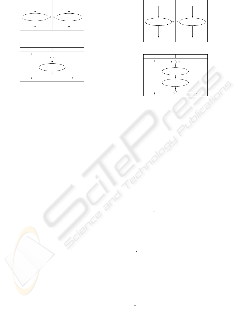
1. sync: The aim here is to provide synchronous exe-
cution for the identity-related activities A1 and A2
shown in Figure 2(a). The operator generates the
integrated model shown in Figure 2(b). The fol-
lowing commands synchronize the flows of both
models leading into one of the two input activities,
removes the other activity, and add two outgoing
flows leading to the former destination of the input
activities:
sync(A1, A2)
begin
addJoinNode(sourceEdge(A1),
sourceEdge(A2),A1); /* J */
addForkNode(A1, targetEdge(A1),
targetEdge(A2)); /* F */
removeNode(A2);
end
2. anyo: Another preferred integration option for
ident
e relationships is anyo (any order). In that
case the user can choose between seq(A1, A2) or
seq(A2, A1) (see below).
3. seq: Figure 3(a) shows the history-related activi-
car:
drive (A1)
Car insurance (BP2)Car dealer (BP1)
car:
is insured (A2)
history-related
E1 E3
E2 E4
(a) Example of history-related ac-
tivities.
is insured (A2)
car:
drive (A1)
car:
Car dealer (BP1) Car insurance (BP2)
D
ME5
E6
E7
E2 E4
E1 E3
’object type = BP1’ ’object type = BP2’
(b) Application of seq.
Figure 3: Example of using seq.
ties A1 and A2. The integration option for this re-
lationship is seq (sequential execution) which pro-
duces the output shown in Figure 3(b). In this case
the activities are set in a sequence according to the
time of their execution.
seq(A2, A1)
begin
addMerge(sourceEdge(A1),
sourceEdge(A2), A2); /* M */
addEdge(A2, A1); /* E6 */
addDecision(A1, targetEdge(A1),
targetEdge(A2)); /* D */
end
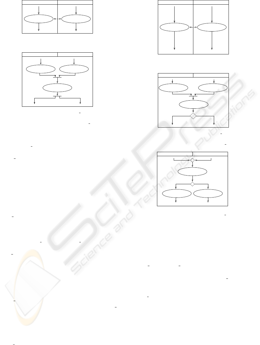
4. sync
a: The example of role-related activities is
shown in Figure 4(a). One preferred integration
option is sync a (synchronous execution and aggre-
gate results). The result is modeled in Figure 4(b).
The following command block synchronizes the
flows leaving the two input activities A1 and A2.
A new activity is added to the model which con-
sists of an aggregation function, e.g., building the
sum of the results of A1 and A2 in a new object.
sync
a (A1, A2)
begin
addActivity(’aggregate: sum’); /* A3 */
addJoin(addEdge(A1,A3),
addEdge(A2,A3), A3); /* J */
addFork(A3, targetEdge(A1),
targetEdge(A2)); /* F */
end
5. sync
r: In the example shown in Figure 5(a) the
activities A1 and A2 are counterpart-related, with
sync r (synchronous execution and relating results)
being preferred. See Figure 5(b). The function
sync r() synchronizes the flows leaving the input
activities A1 and A2 and insert a new activity af-
ter the synchronization which relates the results of
DEFINITION OF BUSINESS PROCESS INTEGRATION OPERATORS FOR GENERALIZATION
513
output:
salary (A1)
output
salary (A2)
Company (BP1) Government (BP2)
E1
E2
E3
E4
role-related
(a) Example of role-related activi-
ties.
sum (A3)
aggregate:
E5 E6
salary (A1)
output:
salary (A2)
output:
F
Company (BP1) Governement (BP2)
E1 E3
J
E7
E8
E2 E4
(b) Application of sync a.
Figure 4: Example of using sync a.
A1 and A2, e.g., select the minimum. The differ-
ence to sync
a is that one of the objects is selected
and the other one will be dismissed.
sync
r (A1, A2)
begin
addActivity(’relate: select minimum’); /* A3 */
addJoin(addEdge(A1,A3),
addEdge(A2,A3),A3); /* J */
addDecision(A3,targetEdge(A1),
targetEdge(A2)); /* D */
addGuardCondition(E2, ’object type = BP1’);
addGuardCondition(E4, ’object type = BP2’);
end
6. stat
s: The activities A1 and A2 are category-
related and represent the first activities in the busi-
ness process. The user chooses one preferred ob-
ject type before the integration process, e.g., a sta-
tic sequence stat s(A1, A2) or stat s(A2, A1). In the
example below the activity A1 is preferred:
stat
s(A1, A2)
begin
addMerge(sourceEdge(A1),
sourceEdge(A2),A1); /* M */
addDecision(A1,targetEdge(A1),
targetEdge(A2)); /* D */
removeNode(A2);
end
7. user
s: The activities in Figure 4(a) are role-
related. Another preferred integration is user
s
(runtime selection based on user input) which pro-
duces the output shown in Figure 7. The following
commands add an activity which handles user in-
put and leads to a decision node which directs to
the user chosen activity.
user
s (A1, A2)
begin
addActivity(’ask user: which role?’); /* A3 */
addMerge(sourceEdge(A1),
Car insurance A (BP1) Car insurance B (BP2)
rate:
calculate (A1)
rate:
calculate (A2)
counterpart-related
E1 E3
E2 E4
(a) Example of counterpart-related
activities.
Car insurance B (BP2)
D
calculate (A1)
rate:
calculate (A2)
rate:
select minimum (A3)
relate:
Car insurance A (BP1)
E3E1
E8
E7
J
E5 E6
E2 E4
’object type = BP1’ ’object type = BP2’
(b) Example of applied sync r.
Figure 5: Example of using sync r.
Which role? (A3)
user:
salary (A1)
output:
salary (A2)
output:
Company (BP1) Government (BP2)
E1 E3
M
E4E2
D
E5
E6
E7 E8
Figure 6: Example of using user s.
sourceEdge(A2),A3); /* M */
addDecision(A3,addEdge(A3,A1),
addEdge(A3,A2)); /* D */
addGuardCondition(E5, ’object type = BP1’);
addGuardCondition(E6, ’object type = BP2’);
end
8. dyn
b: The dyn b option is used for category-
related activities as shown in Figure 7(a). The
output of the integration operator dyn b (dynamic
binding, i.e., automatic runtime choice based on
object type) is modeled in Figure 7(b).
dyn
b(A1, A2)
begin
addEdge(sourceNode(sourceEdge(A1)),
A1); /* E5 */
addGuardCondition(E5, ’object type = BP1’);
addEdge(sourceNode(sourceEdge(A2)),
A2); /* E6 */
addGuardCondition(E6, ’object type = BP2’);
addMergeDecision(sourceEdge(A1),
sourceEdge(A2),
E5,E6); /* MD */
end
ICEIS 2005 - INFORMATION SYSTEMS ANALYSIS AND SPECIFICATION
514

petrol:
select type (A1)
petrol:
select type (A2)
Truck insurance (BP2)
E1
E2
E3
E4
category-related
Sportscar insurance (BP1)
(a) Example of category-related ac-
tivities.
petrol:
select type (A1)
petrol:
select type (A2)
Sportscar insurance (BP1) Truck insurance (BP2)
E2 E4
E1 E3
’object type = BP1’ ’object type = BP2’
E5 E6
(b) Application of dyn b.
Figure 7: Example of using dyn
b.
2.4 Mapping of integration options
The most important eligible combinations between
the high level operators and the activity correspon-
dences are shown in Figure 1. For space reasons,
only a subset of the relationships in (Grossmann
et al., 2004) is given, and we do not address all op-
erator subcategories. Note that the choice of op-
erator is normally not unique, as we do not arti-
ficially overconstrain the considerable variability of
the integration task. However, there is significant
guidance as to which combinations are appropri-
ate. The mapping is defined before the integra-
tion process by the execution of the function ad-
dPreferredIO() and addAlternativeIO() , e.g., execut-
ing addPreferredIO(ident
e rel,sync) and addPreferre-
dIO(ident
e rel,anyo) according to Figure 1.
2.5 Integration choices
The second step of the integration process is the user
choice of integration options for each identified re-
lationship which is mapped to more than one op-
tion. The choices are submitted in the form choo-
seIO(RelShipID,IntOpt) where RelShipID is the cho-
sen relation and and IntOpt is the desired integration
option. After the user has assigned one integration
option to each relationship, the integration can be ex-
ecuted.
3 A LARGER EXAMPLE
We demonstrate our integration approach on two busi-
ness processes involving a car dealer and a car insur-
ance. The two businesses are in different domains,
one is in the insurances business domain and the other
one is in the car trading domain. Both businesses deal
with the same real world object “car”. The integrated
model allows customers to buy a car and a proper car
insurance at the same time. The two models of the
car dealer and the car insurance are shown in Figure 8
as business processes D and A. The integrated model
brings the following advantages to the car dealer and
customer:
• The car dealer can offer an additional service to his
customers.
• The customer does not need to go to the effort of
contacting an insurance company.
• The information about the car only needs to be pro-
vided once.
As explained in Section 1.2, we identify business
process correspondences first which has already hap-
pened in Figure 8. The relationships are represented
by dashed arrows which are labeled with the name
of the specific relationship. In the example we have
identified the following relationships:
• R1 = ident
e(D1,A2): The submitted details about
the car are in both cases identical and so need not
to be provided twice.
• R2 = ident
e(D3,A7): Although both activities be-
long to two different offers, they are transmitted in
identical fashion. Both offers are sent together to
the customer in the integrated model.
• R3 = ident e(D4,A8): The two offers become one
and so will be negotiated together.
• R4 = count(D5,A9): The offers between the cus-
tomer, the car dealer and the insurance company are
saved and administrated separately in each com-
pany but combined later for the customer.
In a next step the proper integration options are
chosen and then applied. According to the Figure 1
we take the preferred integration operators and ap-
ply them on the activities which hold a relationship.
For the four relationships we choose the following op-
tions:
1. chooseIO(R1, sync)
2. chooseIO(R2, sync)
3. chooseIO(R3, sync)
4. chooseIO(R4, sync
a)
The result of the execution sequence is shown in
Figure 9. The integrated model that is produced by the
execution of the integration operators is not satisfac-
tory because the model is not deadlock free. We iden-
tify two different deadlocks: (1) The business process
waits for an incoming instance at a join node which
can not arrive, e.g., after sending the offers to the cus-
tomer, the insurance offer is accepted but not the car
offer, (2) the business process is terminated although
an instance is still running, e.g., the negotiation about
the car offer is successful but the insurance is not. The
problems can be solved by removing redundant con-
trol nodes from the model. In Figure 9 we identify
two pairs of redundant decision nodes, (1) D1 and D2,
(2) D3 and D4. In each of these two cases, both deci-
sion nodes refer to the same real world situation and
DEFINITION OF BUSINESS PROCESS INTEGRATION OPERATORS FOR GENERALIZATION
515
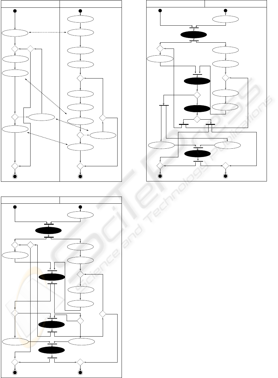
CAR DEALER (D) CAR INSURANCE (A)
car:
details (D1)
type (A1)
cover:
car:
details (A2)
driver:
details (A3)
details (A4)
usage:
calculate prize (D2)
car:
offer:
sending (D3)
select payment (A5)
rate:
calculate (A6)
rate:
sending (A7)
offer:
offer:
negotiate (A8)
offer:
save (A9)
negotiate (D4)
offer:
offer:
save (D5)
yes
identity-e-related
accepted
yes
no
no
identity-e-related
identity-e-related
not accepted
accepted
not accepted
counterpart-related
Figure 8: Car dealer and car insurance example.
CAR DEALER (D) CAR INSURANCE (A)
cover:
type (A1)
calculate prize (D2)
car:
rate:
calculate (A6)
select payment (A5)
rate:
usage:
details (A4)
driver:
details (A3)
save (D5)
offer:
offer:
save (A9)
combine offers
negotiate
J1
yes
F1
F2
’object type = A’
no
D1
D2
D4
D3
’object type = D’
’object type = D’
’object type = A’
accepted
not accepted
’object type = D’ ’object type = A’
accepted
not accepted
no
yes
details
car:
combine offers,
send it to cust.
combine offers
J1
save
Figure 9: Integrated model of car dealer and car insurance.
CAR DEALER (D) CAR INSURANCE (A)
D7
D8
type (A1)
cover:
car:
calculate prize (D2)
details (A3)
driver:
usage:
details (A4)
rate:
select payment (A5)
calculate (A6)
rate:
save (D5)
offer:
offer:
save (A9)
yes no
accepted
not accepted
’object type = D’ ’object type = A’
car:
details
combine offers,
send it to cust.
negotiate
combine offers
combine offers
J2
save
F4
F3
F5
Figure 10: Integrated model after restructuring.
so can be merged.
In Figure 10 the nodes D3 and D4 were merged to
D7, and D1 and D2 were merged to D8. A side effect
of this merging is the need to commute the forks past
the merged decision nodes, i.e., forks F1 and F2 are
replaced by F3, F4, and F5.
An algorithm for automatic detection of deadlocks
is described in (van der Aalst, 1998) where this prob-
lem is defined as soundness property. Our example
does not include any constructs which are not able to
be modeled in Petri nets and so the algorithm can be
applied on our example as well. The final deadlock
free model is shown in Figure 10.
4 CONCLUSION
In this paper we have defined a set of high level in-
tegration operators for business process descriptions
based on UML 2.0 activity diagrams. The opera-
tor definitions are based on semantic categorisation
of the correspondences between the processes to be
integrated that was described in (Grossmann et al.,
2004). These correspondences constrain the set of
appropriate integration operator choices and provide
clear guidelines for the integration task while retain-
ICEIS 2005 - INFORMATION SYSTEMS ANALYSIS AND SPECIFICATION
516

ing the flexibility to choose between different options.
The operators are effective to use due to their simplic-
ity, and provide a unique toolbox for behavior-based
integration.
REFERENCES
Bukhres, O. A. and Elmagarmid, A. (1996). Object-
Oriented Multidatabase Systems: A Solution for Ad-
vanced Applications. Prentice Hall.
CACM (2002). Special Issue on Enterprise Application In-
tegration. Communications of the ACM, 45(10).
Conrad, S. (1997). F
¨
oderierte Datenbanksysteme. Konzepte
der Datenintegration. Springer Verlag.
Frank, H. and Eder, J. (1999). Towards an Automatic Inte-
gration of Statecharts. In Proc. 18th Int. Conf. on Con-
ceptual Modeling (ER’99), LNCS 1728, pages 430–
444, Paris. Springer-Verlag.
Garc
´
ıa-Solaco, M., Saltor, F., and Castellanos, M. (1995).
A structure based schema integration methodology. In
Proceedings IEEE ICDE, pages 505–512, Taipeh.
Grossmann, G., Schrefl, M., and Stumptner, M. (2004).
Classification of business process correspondences
and associated integration operators. In Proc. Int’l
Workshop on Conceptual Modeling Approaches for e-
Business (eCOMO), LNCS 3289, pages 653–666.
Klas, W. and Schrefl, M. (1995). Metaclasses and their Ap-
plications: Data Model Tailoring and Database Inte-
gration. LNCS 943. Springer-Verlag, Berlin, Heidel-
berg.
Parent, C. and Spaccapietra, S. (1998). Issues and ap-
proaches of database integration. Communications of
the ACM, 41(5es):166–178.
Preuner, G., Conrad, S., and Schrefl, M. (2001). View In-
tegration of Behavior in Object-Oriented Databases.
Data and Knowledge Engineering, 36(2):153–183.
Preuner, G. and Schrefl, M. (1998). Observation Consistent
Integration of Business Processes. In Proceedings of
the Australasian Database Conference (ADC), Aus-
tralian Computer Science Communications, Vol. 20,
No. 2, pages 201–212.
Schmitt, I. (1998). Schema Integration for the Design
of Federated Databases. Dissertationen zu Daten-
banken und Informationssystemen, Vol. 43. infix-
Verlag, Sankt Augustin.
Schrefl, M. and Neuhold, E. J. (1988). Object class defin-
ition by generalization using upward inheritance. In
Proceedings of the International IEEE Conference on
Data Engineering, pages 4–13. IEEE Computer Soci-
ety Press.
Stumptner, M., Schrefl, M., and Grossmann, G. (2004). On
the road to behavior-based integration. In Proceedings
1st Asia-Pacific Conference on Conceptual Modelling,
pages 15–22.
van der Aalst, W. (1998). The Application of Petri Nets
to Workflow Management. The Journal of Circuits,
Systems and Computers, 8(1):21–66.
Vermeer, M. W. W. and Apers, P. M. G. (1997). Behaviour
specification in database interoperation. In Confer-
ence on Advanced Information Systems Engineering,
pages 61–74.
DEFINITION OF BUSINESS PROCESS INTEGRATION OPERATORS FOR GENERALIZATION
517
