
GRAPHICAL SPECIFICATION OF DYNAMIC NETWORK
STRUCTURE
Fredrik Seehusen and Ketil Stølen
SINTEF ICT / Department of Informatics, University of Oslo
PB 124 Blindern, 0373 Oslo, Norway
Keywords:
Dynamic network, modeling, language, graphical specification.
Abstract:
We present a language, MEADOW, for specifying dynamic networks from a structural viewpoint. We demon-
strate MEADOW in three examples addressing dynamic reconfiguration in the setting of object-oriented net-
works, ad hoc networks and mobile code networks. MEADOW is more expressive than any language of this
kind (e.g. SDL-2000 agent diagrams, composite structures in UML 2.0) that we are aware of, but maintains,
in our opinion, the simplicity and elegance of these languages.
1 INTRODUCTION
Progress in the history of software engineering can
be characterized by the introduction of levels of ab-
straction to languages and methods with which to de-
velop computerized systems. Indeed, raising the level
of abstraction has been said to improve the cost of
production, longevity, and quality of software systems
(Frankel, 2003).
Graphical languages enable specification of com-
puterized systems at a level of abstraction far higher
than the level of zeros and ones, and many state-of-
the-art languages such composite structures in UML
2.0, are useful for describing the
static
structure
of networks without capturing detailed information
about implementation or execution. Today however,
networks which exhibit dynamic reconfiguration such
as object-oriented networks (Korson and McGregor,
1990), ad hoc networks (Bae et al., 2000; Basagni,
1999; Lee et al., 1999) and mobile code networks
(Fuggetta et al., 1998) are of great practical impor-
tance, and many graphical specification languages
lack concepts with which to express dynamic recon-
figuration at a high level of abstraction.
Having recognized the importance of abstraction
and the wide use of dynamic networks, it is our be-
lief that raising the level of abstraction on which dy-
namic reconfiguration may be specified is beneficial.
In this paper, we aim to address this by proposing
concepts with which to describe dynamic reconfigura-
tion in structural diagrams through the introduction of
the graphical language, MEADOW (ModElling lAn-
guage for DataflOW). We distinguish between dia-
grams for specifying
snapshots
of the network struc-
ture at one point in time, and diagrams for specifying
the
potential
structure that networks may exhibit over
a period of time. A diagram of potential structure
contains information about dynamic reconfiguration
in the sense that it constrains the potential structure
that a network may exhibit during its lifetime. Snap-
shot diagrams may be used to model the structure that
a network may exhibit at the time of creation and at
later points in time. Snapshot diagrams can be related
in time to model dynamic reconfiguration. In addi-
tion, MEADOW distinguishes clearly between static
and dynamic constructs in order to capture both static
and dynamic aspects of networks.
The contributions of this paper are: (1) A con-
ceptual model for dynamic networks. (2) Concepts
for constraining the potential structure that a network
may exhibit over a period of time. (3) Concepts for
relating snapshot diagrams in time. (4) The applica-
tion of these concepts in examples of three kinds of
dynamic networks: object-oriented networks, ad hoc
networks, and mobile code networks.
The rest of the paper is structured as follows. In
section 2, we define the basic network related terms
used in this paper. Section 3 aims to provide suffi-
cient background on MEADOW to allow the exam-
ples to be understood. In section 4, 5 and 6 we employ
MEADOW to specify the structure of three kinds of
dynamic networks. Section 7 describes related work
203
Seehusen F. and Stølen K. (2005).
GRAPHICAL SPECIFICATION OF DYNAMIC NETWORK STRUCTURE.
In Proceedings of the Seventh International Conference on Enterprise Information Systems, pages 203-210
DOI: 10.5220/0002535902030210
Copyright
c
SciTePress

Component Port
Elementary
component
Composite
component
Channel
*
2
*
1
*
0..1
0..1
*
Network
0..1
*
*
*
*
0..1
Figure 1: Basic network concepts
and section 8 concludes this paper.
2 NETWORK CONCEPTS
In order to define a small set of terms with which to
describe networks, we abstract from the distinction of
physical and logical layers. We say that a network is
a set of
components
and a set of
channels
over which
the components communicate. Networks that consist
of computers that are connected by fixed wires, or net-
works that consist of application processes connected
by TCP/IP, are thus conceptualized in the same way.
In the following we define basic network concepts
and use these concepts to define three kinds of dy-
namic networks: object-oriented networks, ad hoc
networks and mobile code networks.
2.1 Basic network terms
The UML class diagram in figure 1 describes the re-
lationships between the basic network terms that are
used in this paper. The definition of these terms
is based on well-established constructs from exist-
ing languages and methods (Broy and Stølen, 2001;
Grosu and Stølen, 2001; ITU-T, 2000; OMG, 2003).
Network A set of components, a set of channels over
which the components communicate, and a set of
sub-networks. We distinguish between a
network
type
and a
network instance
. A network type de-
fines a set of common features shared by all of its
instances, whereas a network instance has its own
identity and its own set of properties that conforms
to the features defined by its type.
Component An entity that communicates with its
environment through a set of referenced ports. A
component may be sent from one component to an-
other via channels. A component has a
behavior
which defines (1) how messages that are received
by its referenced ports are handled, and (2) how
messages are output on its referenced ports. We
distinguish between a
component type
and a
com-
ponent instance
. A component type defines a set
of common features shared by all of its instances.
Each component instance is of a specific type, and
has its own identity and its own set of properties
that conforms to the features defined by its type. A
component can be elementary or composite.
Elementary Component A component that can not
contain sub-components or channels.
Composite Component A component that may con-
tain (reference) sub-components and channels over
which the sub-components may communicate. A
composite component may communicate with its
sub-components.
Port A port provides an interface between a compo-
nent and its environment. A port is either an
input-
port
or an
output-port
. The former receives mes-
sages from a channel, whereas the latter transmits
messages along a channel. A reference to a port
may be sent from one component to another via a
channel.
Channel A channel represents the forwarding of
messages from an output-port to an input-port,
hence a channel is
directed
. A channel is
shared
if
any of the ports it connects are referenced by more
than one component. A channel may or may not
allow message overtaking, message disappearance,
and message duplication.
2.2 Static, Dynamic and Mobile
Networks
Based on the terms introduced in the previous subsec-
tion, we define what we mean by static and dynamic
networks. The following terms are defined with re-
spect to a
model
of a network. Consequently, whether
we say that a network is dynamic or not depends on
how the network is specified, and not necessarily on
the network itself (das Ding an sich).
The terms defined below are understood in various
ways depending on context and research field. Our
definitions are not meant to cover or encompass all
of these understandings, but rather to make precise
what we mean by these terms in MEADOW and in
this paper.
Static network A network is
static
if the sets of ref-
erences to ports and sub-components of all its com-
ponents remain constant throughout any computa-
tion. Hence, in a static network, components and
channels are neither created nor killed during com-
putation.
Dynamic network A network is
dynamic
if (1) the
sets of references to ports and sub-components of
one or more of its components do not remain con-
stant throughout a computation or (2) the set of
components that are part of the network does not
remain constant throughout a computation.
ICEIS 2005 - INFORMATION SYSTEMS ANALYSIS AND SPECIFICATION
204

Object-oriented network A dynamic network in
which (1) each component references a single
input-port and may reference many output-ports,
and (2) references to output-ports may be sent
along the channels. In other words, a component
represents an object, and the single input-port refer-
enced by the component represents a unique object
identifier. The output-ports referenced by a com-
ponent represent object identifiers of other com-
ponents (pointers) that the component is aware of.
References to output-ports that may be sent along
the channels represent object identifiers (pointers)
that may be passed on from one object to another.
Ad hoc network A dynamic network in which (1)
each of the components in its set may be removed
from that set during computation, i.e. every com-
ponent may enter or leave the network during the
lifetime of the network and (2) all the components
may change their communication partners during
the lifetime of the network. An object-oriented net-
work is a special case of an ad hoc network.
Mobile code network A network which enables a
component (representing the mobile code) to be
sent on a channel from one (composite) component
to another (composite) component.
3 MEADOW BASICS
In MEADOW, there is no graphical notation for net-
works, components and channels. Instead they are
modeled by so-called
regions
,
parts
and
connectors
1
,
respectively.
Assume that I is a set of identifiers, n is a natural
number, and that T and i are identifiers. Unless oth-
erwise specified, the following applies throughout the
rest of the paper:
• :T denotes either (1) a component type named T or
(2) a network type named T.
• T denotes an unnamed instance of :T.
• T[n] denotes n unnamed instances of :T.
• i:T denotes an instance named i of :T.
• I:T denotes e:T for each e ∈ I.
We briefly describe the constructs of parts and con-
nectors below.
A part is a subset of the set of all instances of a com-
ponent type. The graphical notation for a part is a
box.
A region is a subset of the set of all instances of a
network type. The graphical notation for a region
is a box with rounded edges.
1
These constructs are similar to parts and connectors in
UML 2.0, and we saw no reason to name them differently.
A connector is a set of channels. Connectors con-
nect parts as channels connect component in-
stances. The graphical notation for a connector is a
directed or bi-directed arrow.
Regions, parts and connectors are either
static
or
dynamic
. Graphically, static constructs have a solid
outline, while dynamic constructs have a dashed out-
line.
There are three kinds of diagrams in MEADOW.
Each of these is described below.
A type diagram is a specification of the potential
structure that all instances of either a component
type or a network type may exhibit during their life-
time. Let S either be a static region, a static part or
a static connector, and D either be a dynamic re-
gion, a dynamic part or a dynamic connector. A
type diagram that (1) defines the features of :T and
(2) contains S and D, specifies that an instance i
of :T must contain (1) exactly the same instances
of S at all times during the lifetime of i:T and (2)
a varying number of the instances of D during the
lifetime of i:T.
A snapshot diagram is a specification of the struc-
ture that all instances of a either component type or
a network type may exhibit at one or more points in
time. Let S either be a static region, a static part or
a static connector. A snapshot diagram that (1) de-
fines the features of :T and (2) contains S, specifies
that an instance i of :T must contain the specified
number of the instances in S at zero or more points
in time. A snapshot diagram can not contain dy-
namic constructs.
A views diagram structures all the diagrams that a
model of a component/network type consists of. It
is a set of diagram declarations and it may classify
these into views. A views diagram may also con-
tain constructs of relating declarations of snapshot
diagrams in time.
4 OBJECT-ORIENTED
NETWORK: ONET
We model an object-oriented network called ONet.
ONet consists of three objects: two objects of class
Sender and one object of class Receiver. Each sender
object always has a reference to the other sender ob-
ject, and one and only one sender object has a refer-
ence to the receiver at any given time. The sender ob-
jects may exchange the reference to the receiver with
each other in order to send messages to it.
The model consists of four diagrams that are ex-
plained in turn.
GRAPHICAL SPECIFICATION OF DYNAMIC NETWORK STRUCTURE
205
re:Receiver
s1:Sender
s2:Sender
:ONet :Type
c:r
c:r
s
o
Figure 2: Type diagram of ONet
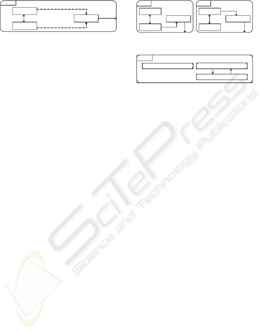
4.1 ONet:Type
Figure 2 presents a
type diagram
(as defined in the top
right corner of the diagram). It specifies the potential
structure that all instances of network type :ONet must
exhibit during their lifetime.
The parts that are labeled s1:Sender and s2:Sender
consist of one component instance named s1 of
:Sender and one instance named s2 of :Sender, re-
spectively. Similarly, the part labeled re:Receiver
consists of one component instance named re of :Re-
ceiver. The three parts in figure 2 are all
static
, be-
cause the graphical notation of a static part is a box
with a solid outline. A static part must always con-
sist of the same instances during its lifetime. In
the current example, this means that each instance
n of :ONet, must contain s1:Sender, s2:Sender, and
re:Receiver at all times during the lifetime of n.
The diagram in figure 2 contains two
static con-
nectors
named s and o and two
dynamic connectors
labeled c:r. A static connector consists of channels
that are always part of a composite component or a
network as long as the components the channels con-
nect are part of the same composite component or net-
work. A dynamic connector, however, is a connector
that consists of channels that may be created or killed
during
the lifetime of the component instances they
connect.
The relationship of channels that a connector con-
sists of is affected by the cardinality of the parts
that the connector connects. In general, a connec-
tor c going from a part P
1
to a part P
2
means that
∀x ∈ P
1
, ∀y ∈ P
2
, there is a channel from compo-
nent instance x to component instance y.
A connector may be directed or bi-directed. The
graphical notation of a directed connector is a line
with an arrowhead at one end, whereas the graphical
notation of a bi-directed connector is a line with an ar-
rowhead in both ends. A bi-directed connector is two
directed connectors containing channels that forward
messages in opposite directions.
The directed connector named o consists of one
channel that goes from re:Receiver to the environment
of the network that re:Receiver is a part of. In other
words, each network n of :ONet must have a channel
that goes from re:Receiver to the environment of n at
all times during the lifetime of n.
The lowermost dynamic connecter labeled c:r is
s1:Sender
:ONet
s
o
initial:Snapshot step2:Snapshot
s2:Sender
re:Receiver
c:r
s1:Sender
:ONet
s
o
s2:Sender
re:Receiver
c:r
Figure 3: Snapshot diagrams of ONet
ONet:Type
:ONet
:Views
initial:Snapshot
step2:Snapshot
Figure 4: Views diagram of ONet
named r, and it consists of one channel named c that
goes from s1:Sender to re:Receiver. The fact that the
connector is dynamic means that the channel the con-
nector consists of may or may not be part of a net-
work n of :ONet during the lifetime of n even if both
components (s1 and re) are part of n. The fact that
both dynamic connectors are equally named and con-
sists of a channel with the same name (c), implies that
only one component instance may transmit messages
on channel c at any given time.
4.2 ONet:Snapshots
A
snapshot diagram
specifies the configuration that
instances of a component type or a network type may
exhibit at
a point in time
.
Our model of ONet consists of the two snapshot
diagrams presented in figure 3. The leftmost diagram
is named initial and the rightmost diagram is named
step2. The name initial is reserved. A snapshot di-
agram with this name specifies the initial structure
that all instances of a component type or a network
type must exhibit upon their creation. In this exam-
ple, all networks of type :ONet must exhibit the struc-
ture specified in the leftmost diagram in figure 3 upon
their creation.
4.3 ONet:Views
The last of the four diagrams that the model of ONet
consists of is presented in figure 4. As indicated in
the top right corner of the diagram, this is a so-called
views diagram
. It contains the declaration of the three
diagrams we have seen so far.
The arrows in the diagram specify how the snap-
shot diagrams are related in time. Let D
1
→ D
2
denote an arrow from diagram D
1
to diagram D
2
for a network type :N. D
1
→ D
2
means that a net-
work n of :N may exhibit the structure specified in
ICEIS 2005 - INFORMATION SYSTEMS ANALYSIS AND SPECIFICATION
206

D
2
after it has exhibited the structure specified in D
1
.
If D
1
→ D
2
→ D
3
, then n may first exhibit D
1
,
then D
2
, then D
3
. However, n may not go from ex-
hibiting the structure specified in D
1
to D
3
without
first exhibiting the structure specified in D
2
. Thus
the constructs for specifying how snapshot diagrams
are related in time are not only a way of increasing
the understandability appropriateness of a model, they
also provide a basis for model checking. This can be
achieved by comparing the specification of how snap-
shot diagrams are related in time with a specification
of the behavior of components.
The type diagrams may also be used as a basis for
a similar kind of model checking. One can check if a
network exhibits a structure during computation that
is not specified in the type diagram. Such an occur-
rence may indicate flaws in the specification of com-
ponent behavior, provided that the type diagram is
correct.
5 AD HOC NETWORK: BCS
In the following we model a network called the Bat-
tlefield Control System (BCS) on the basis of an in-
formal description given in (Clements et al., 2001).
The system is used to control the movement, strategy
and operations of troops in the battlefield.
BCS consists of a commander and a number of sol-
diers. The commander acts as a server and the sol-
diers act as its clients. One of the soldiers acts as
backup. Upon failure of the commander, the backup
will take over as the new commander. Communica-
tion between clients and the server is only through
encrypted messages sent via a radio modem.
BCS is an ad hoc network in the sense that (1) all
components and channels in the network may be cre-
ated or killed during computation and (2) it is dynam-
ically reconfigurable.
We do not to give a full specification of BCS, but
model the scenario of commander breakdown.
5.1 BCS:Views and BCS:Type
We model the system at a logical level (we do not
consider the physical level) as the network type :BCS.
The three diagrams that specify the internal structure
of the network instances of :BCS are declared in the
views diagram presented in figure 5.
Note that three formal parameters are declared in
the top left corner of the diagram. The first is a type
named Rid, the second and third are the constants c
and b of type S (the set of all strings).
The type diagram for :BCS is presented in figure 5.
All parts in the diagram are
dynamic
. The part that
:BCS( type Rid, c:S, b:S ) initial:Snapshot
Rid:Soldier c:Commander b:Backup
qp
:BCS( type Rid, c:S, b:S )
Rid:Soldier[0..] b:Backup[0..1]
p
breakdown:Snapshot
Figure 6: Snapshot diagrams of BCS
is associated with the label c:Commander, has a max-
imum cardinality of one and a minimum cardinality
of zero. Here, this means that a network n of net-
work type :BCS may contain zero or one instances of
:Commander at any given point during its lifetime. A
similar constraint applies for the part that models the
backup.
As declared in the top right corner of the diagram,
Rid is a type, i.e. a set of identifiers. This type is used
as an identifier for the part labeled Rid:Soldier, which
models the soldiers. The maximum cardinality of this
part is #Rid (the cardinality of Rid), and the minimum
cardinality is zero. The maximum and minimum car-
dinality of a part could also be determined by a mul-
tiplicity. E.g. a part labeled Rid:Soldier[3..8] would
have a minimum cardinality of 3 and a maximum car-
dinality of 8.
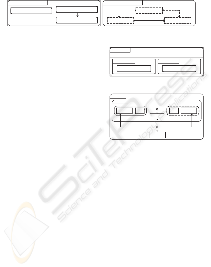
5.2 BCS:Snapshots
Figure 6 presents the two snapshot diagrams that are
declared in the views diagram (figure 5). The diagram
named initial specifies the initial structure that a net-
work of :BCS must exhibit upon its creation. Notice
here that there is no initial connection between the
backup and the soldiers.
The lowermost diagram of figure 6 specifies the
network structure upon breakdown of the comman-
der. Here, a connection is established between the sol-
diers and the backup as a result of the commander not
being part of the network anymore. The multiplicity
([0..]) associated with the part of type Soldier, spec-
ifies that the part has a minimum cardinality of zero
and a maximum cardinality of #Rid (#Rid because the
upper bound of the multiplicity is not defined) at the
time of breakdown. Similarly, the part of type Backup
has a minimum cardinality of zero and a maximum
cardinality of one at the time of breakdown.
6 MOBILE CODE NETWORK:
PDANET
We model a network that is based on a framework for
building context-aware applications in ubiquitous and
GRAPHICAL SPECIFICATION OF DYNAMIC NETWORK STRUCTURE
207
:BCS( type Rid, c:S, b:S )
:Views
BCS:Type
initial:Snapshot
breakdown:Snapshot
:BCS( type Rid, c:S, b:S )
:Type
Rid:Soldier
c:Commander b:Backup
p
q
p
Figure 5: Views diagram and type diagram of BCS
mobile computing settings. The goal of the frame-
work is to offer a location-aware system in which spa-
tial regions can be determined to within a few square
feet, so that one or more portions of a room or a build-
ing can be distinguished.
The framework consists of two parts: (1) mobile
agents and (2) local information servers, called LISs.
The former offers application-specific services which
are associated with physical entities and places. The
latter provide a layer between underlying locating
systems and mobile agents. Each LIS provides the
agents with up-to-date information on the state of the
real world, such as the locations of people, places and
things, and the destinations that agents should migrate
to. For a more detailed description of the framework,
we refer to (Satoh, 2002).
We model a simple network called PDANet that is
based on this framework. The physical components
that constitute PDANet are: a sensor, a LIS, a com-
puter associated with a tag and a personal digital as-
sistant (PDA) also associated with a tag. The tags
make it possible for the sensor to locate the physical
entities (the computer and the PDA). Each tag period-
ically transmits a unique identifier via infrared light
that can be received by the sensor. The tag associated
with the computer is always within the presence of
the sensor, while the tag associated with the PDA may
or may not be within the presence of the sensor at a
given point in time. The sensor uses a radio frequency
to notify the LIS of the tags that are within the pres-
ence of the sensor at a given point in time. The LIS
communicates with the computer and the PDA on the
same radio frequency.
At a logical level, both the computer and the PDA
each have a runtime system (the Java based mobile
agent system Mobile Spaces (Satoh, 2000) for exam-
ple). These runtime systems can execute a mobile
agent we call app. Moreover, app moves from the
runtime system on the computer to the runtime sys-
tem on the PDA when both the previously mentioned
tags are within the presence of the sensor.
6.1 PDANet:Views
We model PDANet as the network type :PDANet. A
views diagram of :PDANet is presented in figure 7.
Here, two type diagrams are declared. These are
:PDANet
:Views
PDANet:Type
type RF, IF; type L = :MA;
Physical:View Logical:View
PDANet:Type
Figure 7: Views diagram of PDANet
:PDANet :Type::Physical
comp:AH
if::IF
Sensor
Tag pda:AHTag
LIS
rf::RF
Cell
Figure 8: Type diagram of PDANet with respect to the phys-
ical view
structured into two views named Physical and Logi-
cal. These diagrams define the potential structure that
instances of :PDANet may exhibit as seen from two
different points of view.
Three types are declared in the header of the views
diagram. These types may be used in the internal
structure of all the diagrams that are declared in the
views diagram. “L = :MA” means that the type L
equals all instances of the component type named
MA. Consequently, connectors associated with the
message type L, consist of channels that may forward
component instances of :MA.
6.2 PDANet:Type::Physical
The type diagram that is contained in the physical
view is presented in figure 8. Here the region la-
beled Cell models the infrared transmission radius of
the sensor. The region containing comp:AH (the com-
puter) and Tag (the tag associated with the computer)
is always within this transmission radius. This region
consists of an unnamed network instance of an un-
named network type (because it is not labeled). The
dynamic region containing pda:AH and Tag models
the fact that the PDA and its associated tag may or
ICEIS 2005 - INFORMATION SYSTEMS ANALYSIS AND SPECIFICATION
208

:PDANet
:Type::Logical
app:MA
::L
comp:AH
MS
app:MA
pda:AH
MS
Figure 9: Type diagram of PDANet with respect to the log-
ical view
may not be within the transmission radius at a given
point in time.
The connector named if of message type IF repre-
sents the infrared communication between the tags
and the sensor. Similarly the connector named rf of
message type RF represents the radio communication
between the computers, the sensor and the LIS. Both
these connectors represent connectivity at the phys-
ical level. Furthermore, both connectors are associ-
ated with a merge-split node (its graphical notation
is a grey filled circle). A connector that is associated
with such a node contains a single shared channel that
all components it connects may forward messages to
and receive messages from.
6.3 PDANet:Type::Logical
The diagram that is contained in the logical view is
presented in figure 9. Here, the internal structure
of the two composite component instances of :AH is
specified. Specifically each instance of :AH contains
an unnamed instance of MS which in turn may or may
not contain app:MA at a given point in time.
The unnamed connector in figure 9 is associated
with the message type L. Since this message type
equals the component type MA (as defined in figure
7), instances of type MA can be sent along the chan-
nels contained in this connector.
7 DISCUSSION AND RELATED
WORK
MEADOW does not currently have a formal seman-
tics, nor is it supported by any computerized tool.
As such, the pragmatic value of the language in it-
self is not as great as many well known languages.
The main goal of this paper is, however, to present
concepts
with which to specify dynamic networks in
structural diagrams. These concepts have been found
useful in the sense that they enable the specification of
dynamic aspects in examples of real networks that can
not be expressed in other state-of-the-art languages.
The question of how useful this added expressiveness
is should ideally be addressed in empirical studies, but
this has not yet been done.
In the following, we compare the concepts of
MEADOW with relevant concepts of state-of-the-art
graphical specification languages. A good overview
of graphical specification methods and techniques can
be found in (Wieringa, 1998). Notable state-of-the-art
languages/methods for modeling structure are Spec-
ification and Description Language (SDL) (ITU-T,
2000), Unified Modeling Language (UML) (OMG,
2003), Real-time Object-Oriented Modeling (ROOM)
(Selic et al., 1994), and FOCUS (Broy and Stølen,
2001). The relevant parts of these languages/methods
which we refer to, are the constructs for structuring
agents in SDL-2000, composite structures in UML
2.0, constructs for structuring actors in ROOM, and
the graphical style in FOCUS.
ROOM separates between static and dynamic con-
structs in the specification of potential structure. The
relevant dynamic constructs are
dynamic actors
and
dynamic actor relationships
. These are similar to,
but less expressive than dynamic parts and dynamic
connectors, respectively. This is due to the fact that
ROOM does not enable the specification of a lower
and an upper bound on multiplicity.
UML does not separate between static and dy-
namic constructs, but the construct called
part
in
UML is similar to
dynamic part
in MEADOW. That
is, UML does enable the specification of upper and
lower bound on the multiplicity of parts and the se-
mantics of this is similar to the semantics of maxi-
mum and minimum cardinality of dynamic parts in
MEADOW. UML does not have the equivalent of sta-
tic components or dynamic connectors (connectors in
UML are similar to static connectors in MEADOW).
Consequently, a specification like the one in figure
2 where dynamic connectors are used, and figure 8
where static components are used, cannot be made us-
ing the constructs of UML.
In SDL, constraints on the maximum number of
instances that a process set (similar to a component
set) may consist of can be imposed. However, a min-
imum bound on the cardinality of process sets cannot
be specified explicitly, and SDL does not distinguish
between static and dynamic constructs.
The graphical style of FOCUS does not distinguish
between static and dynamic constructs, and upper and
lower bounds on the cardinality of components sets
can not be specified. FOCUS does however, unlike the
other languages we have discussed, allow individual
instances of component sets to be named. Without
this, mobile code networks cannot be specified like it
is done in the diagram given in figure 9. Here app is
the name of a component instance, and the two parts
labeled app:MA may consist of the
same
component
instance (at different points in time).
Of all the previously discussed languages, only
UML enables the specification of snapshot structure.
However, UML (and the three other languages) does
GRAPHICAL SPECIFICATION OF DYNAMIC NETWORK STRUCTURE
209

not have constructs for relating such snapshot dia-
grams in time.
8 CONCLUSIONS AND FUTURE
WORK
We have presented the language MEADOW for spec-
ifying dynamic networks from a structural viewpoint.
We have demonstrated the language in three exam-
ples addressing an object-oriented network, an ad
hoc network and a mobile code network. Specifica-
tion of dynamic reconfiguration is achieved through
the clear distinction between
snapshot diagrams
of
the structure that networks may exhibit at a point in
time and
type diagrams
of the structure that networks
may potentially exhibit over a period of time. Dy-
namic reconfiguration is modeled through (1) the con-
struct of relating snapshot diagrams in time and (2)
static/dynamic constructs that constrain the potential
structure of a network.
The obvious advantage of increased expressiveness
in structural diagrams is that they convey more infor-
mation while maintaining a high level of abstraction.
That is, without containing detailed information about
execution or implementation of components. Another
advantage is that constraints in structural diagrams
can be used as a basis for automated model check-
ing by checking whether the behavior of components
abide to their associated constraints expressed in the
structural diagrams.
In order for MEADOW to be used for simula-
tion purposes, it must be used in combination with
a language for modeling behavior such as π-calculus,
STATECHARTS or (certain parts of) FOCUS for ex-
ample. Hence, future work on developing constructs
for specifying behavior of components, or alterna-
tively on how to combine MEADOW with existing
such languages, would be interesting.
MEADOW does not have a formal semantic defi-
nition, nor is it supported by any computerized tool,
hence this is a natural direction of future work.
ACKNOWLEDGEMENTS
The research on which this paper reports has partly
been founded by the Research Council of Norway
through the project SECURIS (152839/220). We
thank Mass Soldal Lund and Ida Hogganvik for useful
feedback.
REFERENCES
Bae, S. H., Lee, S.-J., Su, W., and Gerla, M. (2000). The de-
sign, implementaion, and performance evaluation of
the on-demand multicast rounting protocol in multi-
hop wireless networks. IEEE Network, 14(1):70–77.
Basagni, S. (1999). A mobility-transparent determin-
istic broadcast mechanism for ad hoc networks.
IEEE/ACM Transactions on Networking, 7(6):799–
807.
Broy, M. and Stølen, K. (2001). Specification and develop-
ment of interactive systems. FOCUS on streams, inter-
face, and refinement. Springer-Verlag.
Clements, P., Kazman, R., and Klein, M. (2001). Evalua-
tion software architectures: methods and case studies.
Addison-Wesley.
Frankel, D. S. (2003). Model Driven Architecture - Apply-
ing MDA to Enterprise Computing. Wiley Publishing,
Inc., Indianapolis, Indiana.
Fuggetta, A., Picco, G. P., and Vigna, G. (1998). Under-
standing code mobility. IEEE Transactions on soft-
ware engineering, 24(5):342–361.
Grosu, R. and Stølen, K. (2001). Stream-based specifica-
tion of mobile systems. Formal Aspects of Computing,
13:1–31.
ITU-T (2000). Specification and description language
(SDL), ITU-T Recommendation Z.100.
Korson, T. D. and McGregor, J. D. (1990). Understanding
object-oriented: A unifying paradigm. Communica-
tions of the ACM, 33(9):40–60.
Lee, S.-J., Gerla, M., and Toh, C.-K. (1999). A simulation
study of table-driven and on-demand routing protocols
for mobile ad hoc networks. IEEE Network, 13(4):48–
54.
OMG (2003). UML 2.0 Superstructure Specification. OMG
Adopted Sepcification ptc/03-08-02. Object Manage-
ment Group.
Satoh, I. (2000). Mobilespaces: A framework for build-
ing adaptive distributed applications using a hierarchi-
cal mobile agentsystem. In Proceedings of Interna-
tional Conference on Distributed Computing Systems
(ICDCS’2000), pages 161–168. IEEE Computer So-
ciety.
Satoh, I. (2002). Physical mobility and logical mobil-
ity in ubiquitous computing environments. In Suri,
N., editor, Proceedings of Mobile Agents: 6th In-
ternational Conference (MA 2002), number 2535 in
Lecture Notes in Computer Science, pages 186–201.
Springer-Verlag.
Selic, B., Gullekson, G., and Ward, P. T. (1994). Real-time
object-oriented modeling. Wiley.
Wieringa, R. (1998). A survey of structured and object-
oriented software specification methods and tech-
niques. ACM Computing Surveys, 30(4):459–527.
ICEIS 2005 - INFORMATION SYSTEMS ANALYSIS AND SPECIFICATION
210
