
XML-BASED IMPACT ANALYSIS USING CHANGE-DETECTION
APPROACH FOR SYSTEM INTERFACE CONTROL
Namho Yoo
Department of Computer Science, The George Washington University,
801 22
nd
Street, N.W., Room 730, Washington, DC 20052, USA
Keywords: XML, Impact Analysis, System Engineering, Interface Control, Change Detection, XPath
Abstract: In this paper, an XML-based approach is presented for the impact analysis of interface control in sustained
systems. Once a system is completed developed, it goes into a sustained phase supported by many
interfaces. As new technologies develop, updating and maintaining such systems require non-trivial efforts.
A clear pre-requisite before the deployment of a new system is to clarify the influence of changes on other
systems connected through interfaces. However, as each sustained system manages its own information
separately, integrating relevant information among the interfaced systems is a major hurdle. In our approach,
the XML technology is applied to support impact analysis for interface control architecture using change-
detection approach for the reference. In particular, I focus on messaging interface issues in Health Level
Seven typically used in medical information system and propose a scheme to represent message information
that can be used for the decision support of interface impact between sustained systems.
1 INTRODUCTION
System engineering efforts are vital to make
decisions before making system changes associated
with new requirements. In large-scale system, many
supporting engineers would be involved in the
engineering process through the technical
committee. As system environments change rapidly
and engineering change efforts for impact analysis
increase significantly, many documentation is
considered to carefully examine in terms of non-
functional view as well as functional perspective.
Engineering Change Proposal (ECP), which is one
of the key documentation for configuration
management, contains the description about change
requests/requirements and how they should be
reviewed and implemented(Arnold, 1993). The
proposed approach, therefore, is the extended
framework with impact analysis for interface
control using change-detection approach with XML
like Figure 1.
This paper suggests an effective process and
method to consider interface control requirement
during the impact analysis. For dealing with the
interface control, change detection approach (CDA)
for impact analysis is discussed as a lightweight tool.
In order to handle, interface control requirement,
engineering change proposal (ECP) for impact
analysis are covered.(Yoo, 2004)
Impact Analysis for
Interface Control
IA-IC
Application
IA-IC
Parts
IA-IC
Effectiveness
HL7 Message Interface
XML Technology and DOM Tree
Change Detection Approach
Testing & Implementation
Impact Analysis for
Interface Control
IA-IC
Application
IA-IC
Parts
IA-IC
Effectiveness
HL7 Message Interface
XML Technology and DOM Tree
Change Detection Approach
Testing & Implementation
Figure 1: Extended Impact Analysis for Interface Control
(IA-IC) Framework
Also, since there is system resource information
without specification, common vehicle to exchange
information effectively is required. In this paper,
Extensible Markup Language (XML) technology is
used for supporting engineering change efforts for
impact analysis. An XML is widely used as a
standard for information exchange on the World
Wide Web.(W3C, 2000)
506
Yoo N. (2005).
XML-BASED IMPACT ANALYSIS USING CHANGE-DETECTION APPROACH FOR SYSTEM INTERFACE CONTROL.
In Proceedings of the Seventh International Conference on Enterprise Information Systems, pages 506-509
DOI: 10.5220/0002534305060509
Copyright
c
SciTePress
2 BACKGROUND AND PROBLEM
STATEMENTS
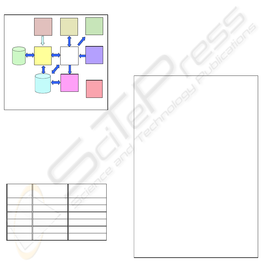
Under considering an world-wide deployed US
health system involving 8 sub-systems A through H
with more than 50 to 200 sites, a impact analysis for
interface control is essential for decision-making.
Consider the interface between systems A and B.
The Health Level Seven (HL7) protocol messaging
supported by the interface engine between A and B
is given in Figure 2 as an example from.
F
B
G
H
E
D
A
C
Reposit
ory
Database
(future)
*
* A has a large number of external system interfaces that have not been shown.
F
B
G
H
E
D
A
C
Reposit
ory
Database
(future)
*
* A has a large number of external system interfaces that have not been shown.
Figure 2: Sustained System Interface Architecture
In table I, the several cases for change are
presented. In change cases (1-3), even though it
may takes for a while to find out the result whether
or not to analyze the impact, system engineer can
say Yes or No. But the analysis result is dependent
to their knowledge and experience. And there are
many cases existed not for sure.
Table I: Change Case Table for the system
Change
Case
System
A
System
B
1 Insert Yes/No
2 Delete Yes/No
3 Update Yes/No
4 Volume N/A
5 Environment N/A
6 Combined N/A
If change cases (4-6) are considered, the situation
for system impact analysis for interface control is
getting harder than previous case. For example, if
the messaging volume of the system A is 25%
increasing, how much of system B is affected by
this change in terms of performance. What about
the system interface impact when the system A
change the security policy and install the new
security patch at the same environment? Is this
change providing impact for the system B? In order
to solve the problem caused by change, the system
testers need to be involved more system and
sustained system project schedule is delayed
accordingly. Creating ECP for Configuration
Management (CM) should be required.
3 XML-BASED IMPACT
ANALAYSIS FOR INTERFACE
CONTROL
In this paper, the way to do system impact analysis
is discussed for system engineer more effectively
and accurately in time manner. The situation of
change request based on health system using HL7
protocol is considered. And the effective
representation is addressed using XML.
<?xml version="1.0" encoding="EUC-KR"?>
<HL7import>
<Segment1>MSH
<Element1>
<Field1>^</Field1>
<Field2>~</Field2>
<Field3>\</Field3>
<Field4>amp</Field4>
</Element1>
<Element2>ADT1</Element2>
<Element3>MCM</Element3>
<Element4>LABADT</Element4>
<Element5>198808181126</Element5>
<Element6>Security</Element6>
<Element7>
<Field1>ADT</Field1>
<Field2/>
<Field3>A01</Field3>
</Element7>
<Element8>MSG00001</Element8>
<Element9>P</Element9>
<Element10>2.3.1</Element10>
</Segment1>
<Segment2>EVN
<Element1>A01</Element1>
<Element2>198808181123</Element2>
</Segment2>
<Segment3>PID
<Element1>1</Element1>
<Element2>
<Field1>PATID12345</Field1>
<Field2>M11</Field2>
<Field3>ADT</Field3>
</Element2>
<Element3>MR</Element3>
<Element4>
<Field1>MCM</Field1>
<Field2/>
<Field3>123456789</Field3>
<Field4/>
<Field5/>
<Field6>USSSA</Field6>
<Field7>SS</Field7>
</Element4>
<Element5>
<Field1>JOHNES</Field1>
<Field2>WILLIAM</Field2>
<Field3>A</Field3>
<Field4>III</Field4>
</Element5>
<Element6>M-</Element6>
<Element7>C</Element7>
<Element8>
<Field1>1200</Field1>
<Field2>N</Field2>
<Field3>ELM</Field3>
<Field4>STREET</Field4>
<Field5/>
<Field6>GREENSBORO</Field6>
<Field7>NC</Field7>
<Field8>27401-1020</Field8>
</Element8>
<Element9>GL</Element9>
<Element10>(919)379-1212</Element10>
<Element11>(919)271-3434</Element11>
<Element12>S</Element12>
<Element13/>
<Field1>PATID12345001</Field1>
<Field2>2</Field2>
<Field3>M10</Field3>
<Field4>ADT1</Field4>
<Field5>AN</Field5>
<Field6>A</Field6>
<Element14>123456789</Element14>
<Element15/>
<Field1>987654</Field1>
<Field2>NC</Field2>
</Segment3>
<Segment4>NK1
<Element1>1</Element1>
<Element2>
<Field1>JOHNES</Field1>
<Field2>BARBARA</Field2>
<Field3>K</Field3>
</Element2>
<Element3>
<Field1>WI</Field1>
<Field2>WIFE</Field2>
</Element3>
<Element4>
<Field1>NK</Field1>
<Field2>NEXT OF KIN</Field2>
</Element4>
</Segment4>
<Segment5>PV1
<Element1>1</Element1>
<Element2>I</Element2>
<Element3>
<Field1>2000</Field1>
<Field2>2012</Field2>
<Field3>01</Field3>
</Element3>
<Element4>
<Field1>004777</Field1>
<Field2>LEBAUER</Field2>
<Field3>SIDNEY</Field3>
<Field4>J.</Field4>
</Element4>
<Element5>SUR</Element5>
</Segment5>
</HL7import>
Figure 3: Converted XML from HL7 Sample Message
Figure 3 is the corresponding representation of
HL7 example. XML representation is more
understandable for system engineer and scalable to
different format for future needs. Whenever
XML-BASED IMPACT ANALYSIS USING CHANGE-DETECTION APPROACH FOR SYSTEM INTERFACE
CONTROL
507
appropriate, it can be possibly triggered and
converted by the development.
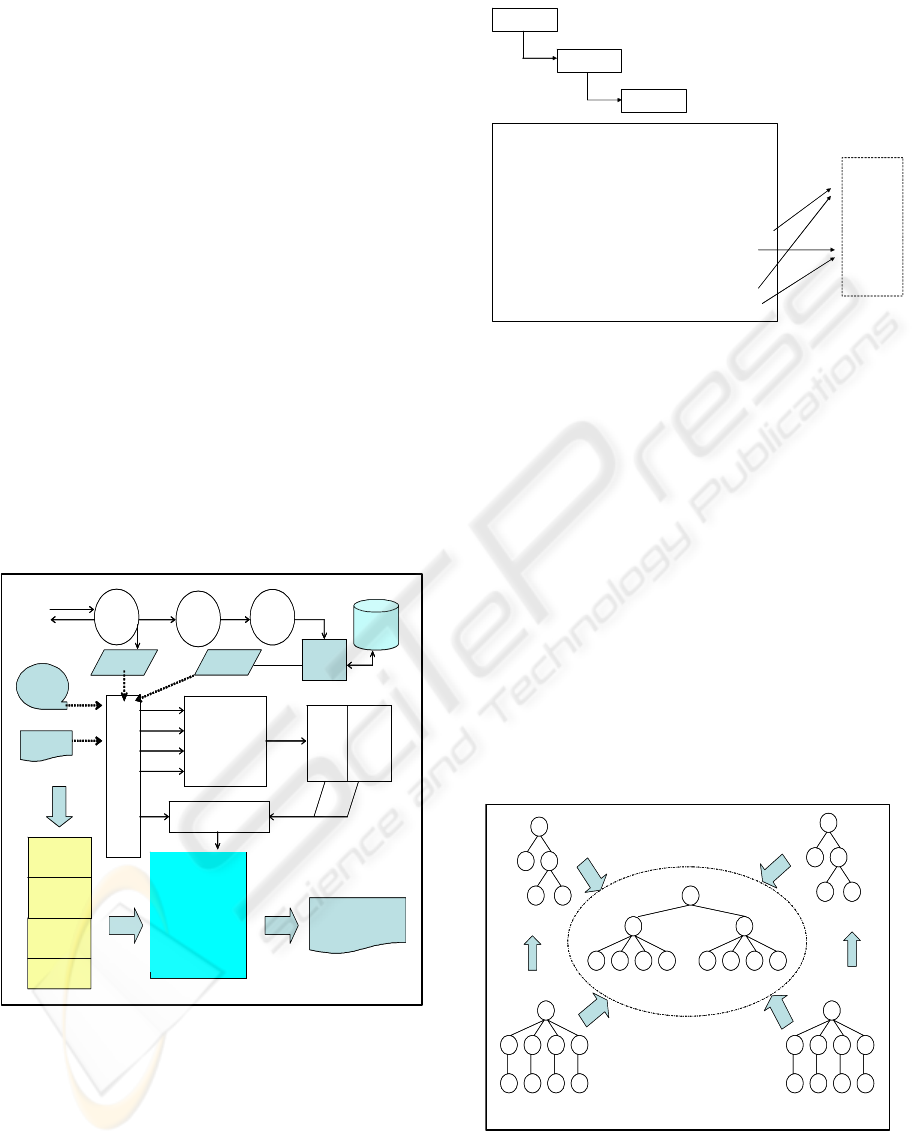
Figure 4(upper part) depicts the ideal data flow
among the different modules in this interface. The
HL7 message received by the communication
modules from the external system goes to the HL7
engine module. After the HL7 engine module edits
the HL7 message, it passes the decoded data to the
queue and the encoded acknowledgement back to
the communication module. The communication
module then sends back the acknowledgement to
the external system. The parsed data stored in the
queue will then be mapped and sent to the receiving
system/HL7 internal file. Likewise, if the edit is not
successful, no data will be sent to the
parsed/destination file.
Figure 4 (lower part) shows the XML based
information architecture mapping to each offline or
online assets. Our focus is regarding offline assets
such as documents and data dictionary. Using these
artifacts, the DTD and Document XML are
generated. However as there exist some
inconsistency or some gaps between the document
and real system, it is also required to verify the
information using online log file and parsed data.
HL7
Engi ne
HL7 Msg
Ack
Queue
Decoded
Da ta
Mapped Data
Par sed
Data
Appli cation
Database
Log File
Dat a Dict ionar y
Doc ume nt s
Impact Analysis
For Interface Control
Res ul t
Log XML
Me s s age
XML
DTD XML
Doc u X ML
SysA DOM Checker
SysB DOM Checker
Compare DOM
Filtering
Saving Difference
Maintain IIA
Verifying Result
CSV_ 2_ XML
XML_2_ DOM
Up load
Web
TXT_2_XML
Ex
Tract
or
HTML_2_XML
DAT _ 2_ XML
Save
Loc al
Dis k
py
Rul e File
Figure 4: Proposed XML based IA-IC Architecture
As defined by HL7 standard, each message is
composed of logical groupings of data entities,
named message, segment, and elements. Some
segments may be optional or repeatable in a
message. Figure 5 depicts the logical structure of
the entities and some examples.
Message
Segment
Element
ADT/A01
HL DG ADMIT PATIENT
~
~
PID
HL DG PATIENT ID
~
PV1
HL DG PATIENT VISIT
~
~
PID
~
HL DG PATIENT ID INTERNAL
~
HL COUNTRY CODE
~
PV1
~
HL DG ADMISSION TYPE
~
ADMITTING DOCTOR
~
Not
Applicable
Applicable
System B
Figure 5: HL7 Example for IA-IC
Based on the testing for the research with XML-
based representation, an HL7 message transferred
from system A to system B used is found only about
30% of the time in terms of message-level and only
50% of the messages are being used if I consider
element-level. In other words, by using XML-based
message modeling the meaningful portion of
messages is identified for decision-making and is
managed the part required to enhance interface
impact analysis as well as updating impact analysis
for each system.
4 CHANGE-DETECTION
APPROACH
The time for efforts and potential error is mitigated.
IA-IC XML DOM Tree
IC Rule Tree
(System A)
IC Rule Tree
(System B)
IC Message Tree
(System A)
IC Message Tree
(System B)
IA-IC XML DOM Tree
IC Rule Tree
(System A)
IC Rule Tree
(System B)
IC Message Tree
(System A)
IC Message Tree
(System B)
Figure 6: IA-IC XML DOM Tree
This paper suggests extended IA-IC tree by
considering combined scheme with HL7 testing and
change detection approach by XML technology.
ICEIS 2005 - INFORMATION SYSTEMS ANALYSIS AND SPECIFICATION
508
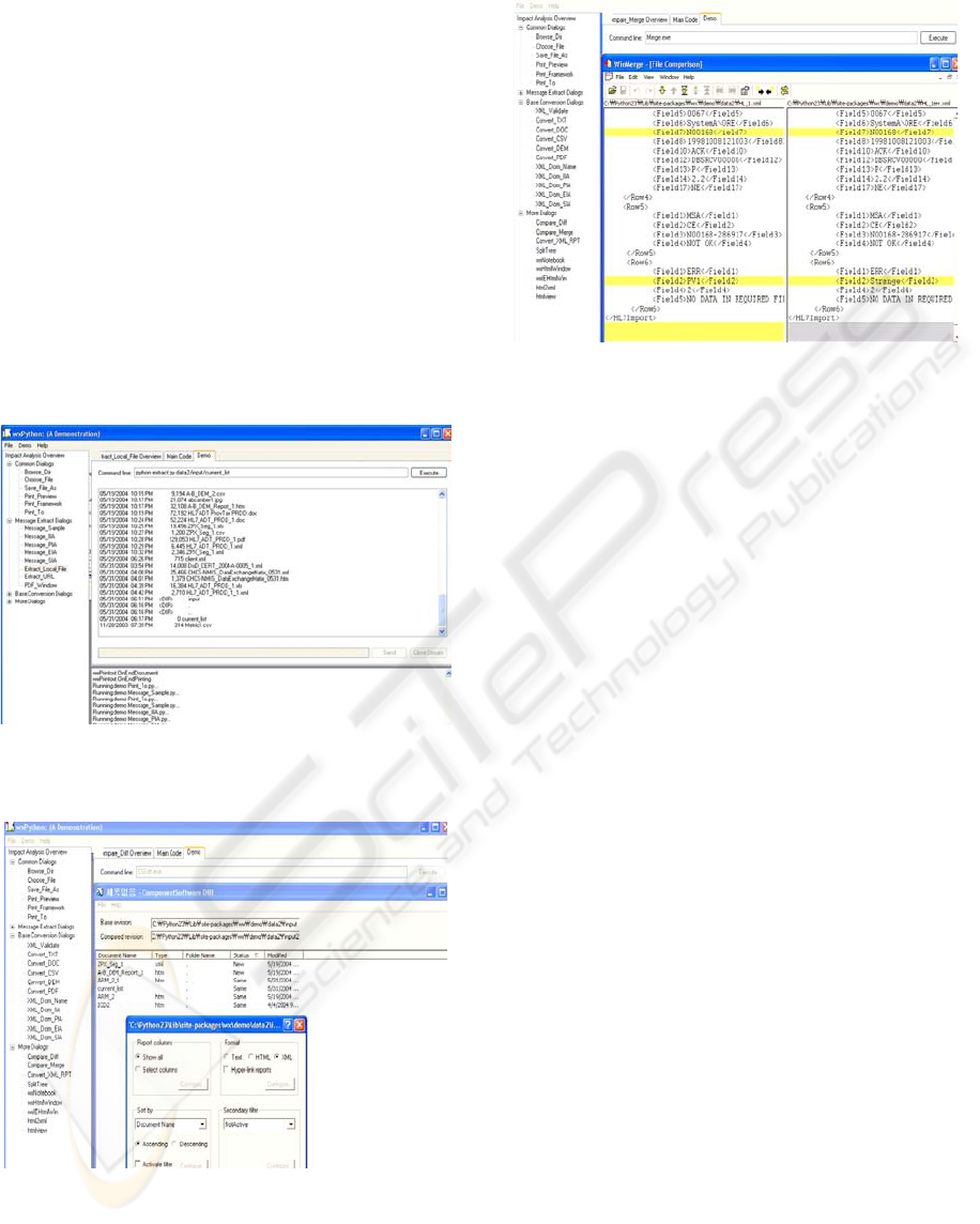
Figure 6 is an example of DOM integration with
message trees and rule trees.
For traversing the information under the XML
DOM tree structure, given algorithm using XPath
and XSLT is used. XPath takes a navigational
approach for specifying the nodes to be selected,
hence a large number of navigational axes have
been defined in XPath.
5 IMPLEMENTING XML-BASED
IA-IC
A common environment as shown(Figure 7) can be
built for the simulation of the performance
requirement and the impact analysis on the interface.
(a) Extracting the change of artifacts
(b) Comparing the difference of control documents
(c) Comparing the change with XML
Figure 7: Executable IA-IC Architecture Implementation
6 CONCLUSIONS AND FUTURE
WORK
The engineering issues are discussed to meet
changing functional requirement in systems
maintenance phase. In particular, the impact
analysis for interface control is focused on in the
presence of interface requirement and performance
requirement in large scaled sustained system. A
baseline using XML-based representation to handle
changing functional requirements is considered with
the process for impact analysis. The XML-based
change-detection approach enables supporting
engineers’ collaboration effectively to meet the
limited time requirement. Through a health system
example, engineering steps are addressed for
integrating information and sharing analysis result
during ECP process.
REFERENCES
Arnold, R., Bohner, S., 1993, Impact Analysis – Toward
A Framework for Comparison, In Proceeding of
Conference on Software Maintenance, pp 27-30,
September.
W3C, 2000, Extensible Markup Language (XML) 1.0 ,
W3C Recommendation, October
Yoo, N., 2004, Impact Analysis using Performance
Requirement with Application Response
Measurement in Sustained System, In Proceedings of
the ISOneWorld Conference.
Yoo, N., 2004, An XML-based Engineering Change
Impact Analysis with Non-Functional Requirements,
In Proceeding of SERP.
XML-BASED IMPACT ANALYSIS USING CHANGE-DETECTION APPROACH FOR SYSTEM INTERFACE
CONTROL
509
