
A Practical Approach to Goal Modelling for Time-
Constrained Projects
Kenneth Boness
1
, Marc Bartsch
1
, Stephen Cook
1
and Rachel Harrison
1
1
Department of Computer Science, The University of Reading, Reading, Berkshire,
RG6 6AY, UK
Abstract. Goal modelling is a well known rigorous method for analysing
problem rationale and developing requirements. Under the pressures typical of
time-constrained projects its benefits are not accessible. This is because of the
effort and time needed to create the graph and because reading the results can
be difficult owing to the effects of crosscutting concerns. Here we introduce an
adaptation of KAOS to meet the needs of rapid turn around and clarity. The
main aim is to help the stakeholders gain an insight into the larger issues that
might be overlooked if they make a premature start into implementation. The
method emphasises the use of obstacles, accepts under-refined goals and has
new methods for managing crosscutting concerns and strategic decision
making. It is expected to be of value to agile as well as traditional processes.
1 Introduction
The practice of managing software development projects from well-understood
requirements has many advantages but these advantages may seem inaccessible in the
commercial world where time-to-market is a primary consideration [3]. In such cases
there is a strong pressure to “get-on with it”. If we accept that requirements analysis
can be an economic way of reducing the risks of building the wrong product or
attempting an unrealistic implementation then we need requirements engineering tools
that are compatible with time-constrained approaches to software development. For
example, tools that help stakeholders and project managers to discover and locate
project failure risks in the early stages and to show which bits can safely be “got-on-
with”. The decision to start building a system is, in practice, a risk management
decision made by the stakeholders. It would be more soundly based if the
stakeholders were better informed about each other’s goals and assumptions, and the
choices, risks and costs that follow.
Goal based requirements analysis (Mylopoulos, Chung, Yu, 1999; Yu, 1997; [6];
[1] can reveal structural completeness, consistency and rationale. It can also show the
options for architectural choice and the soundness of the representation of the
purpose
1
in hand. The question is whether this approach can be practicable in the
time-pressed industrial regime. A common view is that goal oriented methods, such as
1
i.e. An intention to define and solve a problem.
Boness K., Bartsch M., Cook S. and Harrison R. (2005).
A Practical Approach to Goal Modelling for Time-Constrained Projects.
In Proceedings of the 1st International Workshop on Requirements Engineering for Information Systems in Digital Economy, pages 37-50
DOI: 10.5220/0001423800370050
Copyright
c
SciTePress

KAOS [4], can be time-consuming and can result in very complex representations;
neither feature being attractive in time-constrained projects.
This paper introduces a new adaptation of the KAOS approach to goal analysis.
This new approach is lightweight and includes some representational enhancements to
provide ease of use and lowered complexity of representation. We have assumed that
requirements only attain maturity by an iterative-incremental process that starts with a
rough sketch. Given the time-constrained scenario discussed above, it is essential that
the visualization provides a clear and comprehensive representation that emphasizes:
1. Simplicity of construction
2. A visual language that is easy to understand by all negotiating stakeholders
3. A means to tolerate and represent incompleteness and imprecision
This paper is structured as follows: In section 2, related work is described. Section
3 introduces our lightweight approach to goal-oriented requirements engineering.
Section 4 focuses in more detail on specific model properties. Section 5 presents an
exemplar that uses our approach. Section 6 comprises a discussion and further work
and section 7 presents conclusions.
2 Related Work
Anton and Potts present the Goal-Based Requirements Analysis Method (GBRAM)
[1]. This approach consists of a number of activities: Goals and their responsible
agents are identified, organised, pruned and elaborated. Finally, goals are translated
into operations.
The KAOS framework by Lamsweerde et al. [6], [11] is a more comprehensive
goal-oriented approach, spanning goal analysis through elaboration and
operationalisation to object modelling. Within this model, obstacles describe
impediments to achieving a goal that has to be resolved. The KAOS model has been
used in this work as a starting point for a lightweight approach to goal-oriented
requirements engineering.
Mylopoulos et al. (Mylopoulos, Chung, Yu, 1999) introduced the idea of
satisficing a soft goal or non-functional requirement. Soft goals are goals that do not
have a clear-cut criterion for when they are satisfied. They are said to be satisficed
when there is enough positive and little enough negative evidence that justifies their
satisfaction. This concept is implicit in the KAOS concept of a “soft goal”. One of
the simplifications introduced in this work, is to drop the distinction between “hard”
and “soft” goals and to emphasize the active role of stakeholders in validating goal
refinements and determining precise acceptance criteria, as [8] recommends.
An agent-based approach to goal-oriented requirements engineering is presented
by Yu (Yu, 1997) in his i* model. The main concept in i* is the agent, an intentional
actor with motivations, goals, beliefs and abilities. This can be contrasted with the
less psychological perspective in KAOS and the present work. In i* dependencies
exist between agents who influence the achievement of goals, the performance of
tasks, and the furnishing of resources. In our approach, we distinguish between the
38
stakeholder role of understanding and owning goals and the agent role of performing
tasks.
3 A Lightweight, Goal-Oriented Approach: KAOS Lite
We have created a goal analysis method based on KAOS emphasizing the benefits of
simplicity in the modelling and visualization of goals.
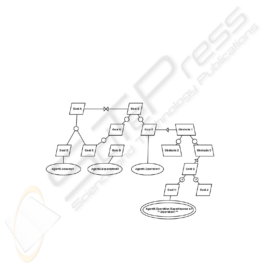
Fig.1 shows a possible goal graph using most of the node entities and edges that
are supported in KAOS Lite. Goals A and E are root goals whose existence depend
solely on the stated intentions of the stakeholders. They are connected through edges
to a conflict operator (the bow-tie). The conflict operator refers to the fact that
achieving Goal A poses a conflict of some sort for achieving Goal E, which needs
attention by the stakeholders or requirements engineer.
Goal A is refined into sub-goals B and C. The refinement operator (small circle)
can have multiple children and the set of children must be satisfied to achieve the
parent goal; i.e. the refinement operator behaves as an AND gate. Goal D is
operationalised but also appears to be a root goal. Goal E is OR refined into goals K
and F. Goal F is operationalised but is also obstructed by Obstacle 1. An obstacle is
an impediment to achieving a goal. Unless an obstacle is resolved, a goal graph
cannot be considered complete.
Fig. 1. Illustrative goal graph
Obstacle 1 is OR refined into sub-obstacles 2 and 3. Obstacle 2 is not resolved but
obstacle 3 is resolved by goal G. Goals H and J are alternative refinements of goal G;
called a strategic OR and can be used for architectural reasoning. Of the two choices
only Goal H is operationalised. The process operationalising Goal H shows a shadow
background to indicate that it superimposes itself on certain other processes (in this
39

case the process that operationalises Goal F – this is discussed below in “crosscutting
structures”).
Goals B, C, D, F, H and J are leaf goals that should be operationalised as either
requirement, assumption or expectation. A requirement is something that the system-
to-be must do or a property it must have. An assumption is an invariant property that
the system-to-be depends on. An expectation is a property or behaviour of the
environment that the system-to-be depends on but cannot guarantee. In KAOS Lite
they are represented uniformly as processes assigned to agents. However, the agents’
responsibilities differ. In the case of requirements, the agent is an architectural
component of the system-to-be. For expectations and assumptions, the responsibility
lies with agents drawn from the stakeholders or the environment. This provides a
basis for negotiating with stakeholders about the balance of responsibilities, e.g.
tradeoffs between system complexity and users’ required skills.
Continuing with Fig.1, only Goals B, C and D are operationalised: B as an
assumption with Agent 3 assigned responsibility for its validity; C by an operation
assigned to Agent1 for satisfaction; and D by an expectation assigned to Agent 2 for
satisfaction.
4 Model Properties
This section highlights some distinctive features of KAOS Lite that are particularly
relevant for time-constrained projects.
4.1 Refinement and Architectural Choice
There are two types of OR refinement in a goal graph: strategic OR, representing an
alternative implementation strategy (build this or that), and run-time OR, representing
a necessary logical inclusion in a goal refinement (the parent goal is true at run time if
either this or that are true). KAOS Lite distinguishes them by annotating the
refinement operator with a ‘?’ symbol.
In Fig. 2. (a) we are stating that at run-time the activity will be closed by receipt of
either a telephone message of an email. In Fig. 2 (b) we are stating that as a matter of
design we will choose an implementation based on one or other of the possibilities.
40
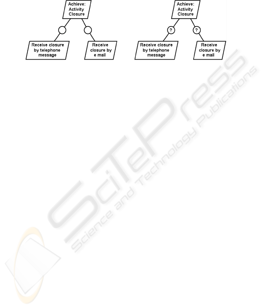
Fig. 2. Run-time OR (a) and strategic OR (b)
It is important to distinguish strategic choices because they often represent policy
decisions that have architectural, cost and schedule implications. In general, only one
branch will be elaborated and eventually implemented. The alternative branches are
modelled schematically to assist documenting the rationale for the stakeholders'
preference. This can be valuable in agile approaches because architectural decisions
may have to be revisited as a result of evolution in either a system's requirements or
its environment.
4.2 Obstacle
One of the expected benefits of goal analysis is the identification of obstacles. From a
stakeholder's perspective, an obstacle is an event, state or situation that could prevent
a project from achieving its goals. For example, ‘demand exceeds capacity’ is a
potential obstacle in many sales-driven projects because that situation would
contradict a goal of ‘meet customer expectations’. Three obstacles are shown in Fig.
1.
It is often the case that in the early stages relatively few goals are specified. This
leads to the danger that the implementation is naïve [4]. It is not uncommon to
discover that the easy part of the implementation is the intended functionality.
“Getting-on-with-it” tends to focus on the main functionality. However the obstacles,
which include the exception conditions, are often the cause of most development and
testing effort. Furthermore it is often the case that unnoticed obstacles cause the
stakeholders to be disappointed with the delivered product; with potentially serious
cost consequences. In KAOS Lite goals are considered equally as defining the problem
to be solved. The example below shows that they are a rich source of the necessary
goals that may easily have been overlooked resulting in a large body of implemented
code that needs refactoring and supplementing to cope with them.
Although goals and obstacles are logically symmetrical (Lamsweerde sometimes
refers to obstacles as anti-goals) stakeholders often have asymmetric knowledge of
them. For example, in the earliest stages of requirements engineering for an E-type
system, the goals may be vague and volatile. However, it is possible to infer many
likely obstacles by drawing on previous experience of similar projects, i.e. through
case-based reasoning. Furthermore, few software projects begin with a blank slate;
41

usually they address some existing problem. Thus a goal graph can be initialised as a
collection of obstacles to be resolved. Goals can be added as stakeholders discover
them through a process of obstacle refinement.
KAOS Lite like KAOS includes obstacles but in KAOS Lite their use is encouraged
since it is often the case that problems may be represented more rapidly as obstacles
than goals; of course ultimately every obstacle requires resolution by a goal or a goal
refinement.
4.3 Crosscutting Structures
Applying a goal-based approach to requirements engineering can lead to overly
complex goal graph representations. The same goal or obstacle can be found scattered
in several places and focusing on only one part of a goal graph reveals several
tangling concepts. Such scattering and tangling turns reading and understanding of the
goal graph into a problem. When it comes to modifications of the goal graph due to
volatile or only partly known requirements, the changes have to be applied at different
places, which hinders a re-factoring of the goal graph and increases the likelihood of
errors.
Aspect-Oriented Programming [9] offers an approach to dealing with complex goal
graph representations. At its core is the idea of an aspect or crosscutting concern as a
modular unit. A concern is a thing of particular interest for a subset of stakeholders
and a crosscutting concern is a concern that cuts across other concerns. For example,
persistence or localization cut across the main concern(s) of the system. Aspects
represent modular units which become most apparent in Aspect-Oriented
Programming and Modelling, where crosscutting concerns are expressed through new
modularized programming structures, the aspect in AspectJ [10], for example, or
through extensions to UML [5]. When crosscutting concerns have to be expressed in a
goal graph, it is very likely that the problems of tangling and scattering described
above occur, since the crosscutting nature of this concern is expressed through
multiple instances of goals or obstacles or through the multiple usage of edges
between entities.
KAOS Lite treats the problem of crosscutting structures at process level through
superimposed processes. A superimposed process is a process that superimposes its
functionality onto other processes thus revealing its crosscutting nature. For example,
a localization concern superimposes itself on all processes that carry out output to a
screen, in order to translate all output before it is sent to the screen. Superimposed
processes support the idea of changing requirements. Changes to the localization
requirement that have an effect on its processes need only be applied to one concern
which is represented through its separate goal graph.
In the KAOS notation, processes are expressed through ovals and are always
carried out by an agent, either an internal software agent or an external agent,
expressed through a diamond shape. To decrease complexity through a limited
number of shapes, in KAOS Lite agents and processes are merged into one oval,
expressing the processes an agent has to carry out. Superimposed processes will be
visualized through a double oval, expressing that one process superimposes itself on
another. The detailed relationship between the imposing and superimposed processes
is undefined, since an actual design and implementation should be possible with either
42

aspect or non-aspect-oriented languages. The set of processes that will be
superimposed will be described for example in a combination of regular expressions.
Fig. 1 shows an example of a superimposed process. Through superimposed
processes, scattering in goal-graphs can be reduced and thus enhance their readability
and understandability.
5 An Exemplar
Here we take an early requirements sketch in the form of a high level problem
statement and show how we can rapidly create a goal based representation that gives
us confidence to proceed with implementation in some areas and reason for caution in
others. Fig. 3 shows the problem statement.
Problem Statement
The customer, WeighCom, wishes to produce a set of walk-on scales that
can be installed in public places and used by any passers by to measure their
weight, height and body mass index (BMI) and receive a business card sized
printed record on the spot. Normal operation is for the user to step onto a
pressure mat facing an instruction screen and standing under an acoustic ranger.
The measurements are made once the user pays a fee of 1 Euro into a receptor.
WeighCom has an excellent reputation for always delivering a reliable
service or returning the money. This reputation is of paramount importance to
them.
WeighCom specifies that the solution must use certain components: pressure
mat PM; coin receptor (CR); an acoustic ranger (AR) and integrated processor
with alpha numerical visual display and user selection touch screen (IP). All of
these are to be controlled through software using an API (application
programming interface). These components support an existing assembly in
which the whole is weather proof and reasonably vandal proof.
Fig. 3. WeighCom problem statement
In our experience, projects in industry often start the implementation phase armed
with not much more than such a problem statement. Similarly, after showing the
statement to colleagues they produced an implementation within two days. However,
this implementation focused on normal functionality which as shall be seen, is only a
small part of the problem. Some of the risks of premature ‘code-cutting’ are readily
exposed in the first few steps of analyzing the goals and obstacles, as we now
demonstrate.
To begin, the implicit goals in Fig. 3 need to be identified. Various sets may be
postulated and Fig 4 lists one set:
<G1>”Produce a set of walk-on scales”.
<G2> “Installed in public places and used by any passers-by”
<G3>”Normal operation”
43

<G4> “Reputation”.
<G5> “Solution must use certain components”.
<G6>”measure their weight, height and body mass index (BMI) and receive a
business card sized printed record on the spot.”
<G7>”user to step onto a pressure mat facing an instruction screen and standing
under an acoustic ranger.”
<G8>The measurements are made once the user pays a fee of 1 Euro into a
receptor.
Fig. 4. Candidate list of goals
This choice of goals though reasonable is debatable and for that reason must be
tested with the stakeholders. Negotiations may take place to identify the most fitting
choice.
The initial choice of goals may also be helped by applying quality checklists and
other heuristics. These techniques have not been used here. Also it may be noted that
Fig. 4 does not make the underlying business case explicit, with the consequence that
the analysis may overlook at least one significant root goal.
For the purpose of this paper the list in Fig. 4 is taken as a baseline. A quick survey
of these goals shows: G1 makes a plausible choice as a root goal supported by G2
through G5. Goal G3 represents functional requirements whilst G2, G4 and G5 are
non-functional. G5 constrains the implementation and will crosscut the leaf goals
stemming from G3. Similarly G2 and G4 are likely to crosscut G3.
The user interface of our tool implementing KAOS Lite allows a drag and drop
operation from Microsoft Word. All the examples below have used this. Minor
modifications to the goal texts in Fig. 4 have been introduced to improve clarity.
G6 through G8 could be refined individually into sub goals. However is this
necessary; at least initially? They may be recognized as three stories, or even one
large story, and in agile fashion it may be expedient to accept the actual code of the
implementation as the refinement. In Fig. 5, G7 and G8 are combined and replaced
with a new G9 in the hope of freeing G9 as soon as possible for implementation.
The process in Fig. 5 was what our colleagues implemented in two days. However
there are ‘What if?’ questions to be answered including:-
1. Suppose the public do not recognize the invitation to use the scales?
2. Suppose the users do not stand properly to allow the acoustic ranger and
pressure mat to make their measurements sufficiently accurate?
3. Suppose the scales are not ready to operate and execute a transaction to
completion after a user has paid?
4. Suppose that after a transaction has begun it cannot then be completed?
44
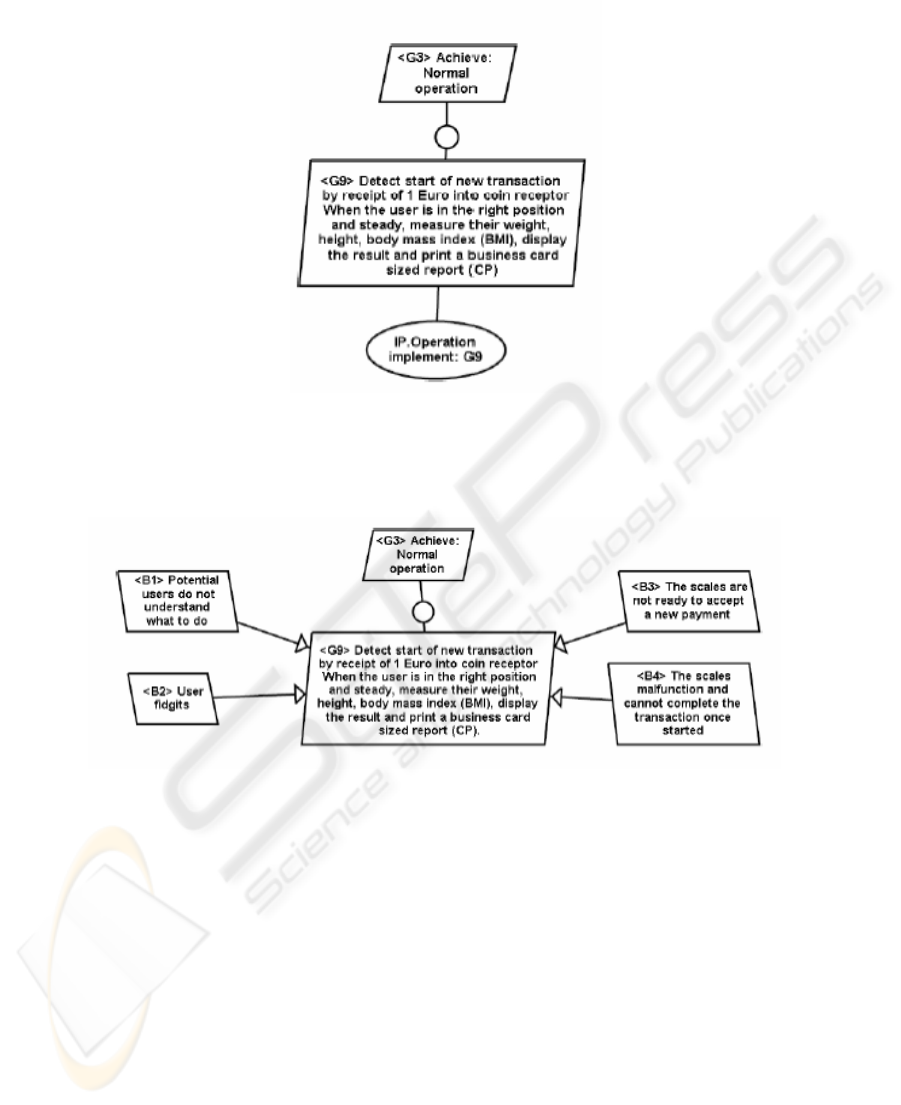
Fig. 5. Normal operation with a basic operationalisation process
These are represented in Fig. 6 as obstacles B1, B2, B3 and B4. Most would also
obstruct G4.
Fig. 6. Obstacles to normal operation
In Fig. 6 the real development problem is beginning to emerge. Clearly
consultation with stakeholders is needed. Whereas B1 may be very easily resolved
with an information screen, resolving the others could be complex. Depending on the
views of the stakeholders and the potential cost and development time, the
ramifications need to be discussed with the stakeholders. For example what policies
apply to repayments and to the protection of reputation (G4)?
Obstacles tend to refine in OR logic as opposed to the normal AND logic of goals.
If obstacles are taken to be negative goals then this is an example of de Morgan’s law.
A speculative refinement of B4 is shown in Fig. 7. This illustrates a strategic-OR
where the stakeholders are offered the choice of relatively low investment in goal G19
or the more complex alternative in G20. In this figure the analyst has guessed that
G19 would be preferred and has also operationalised it.
45
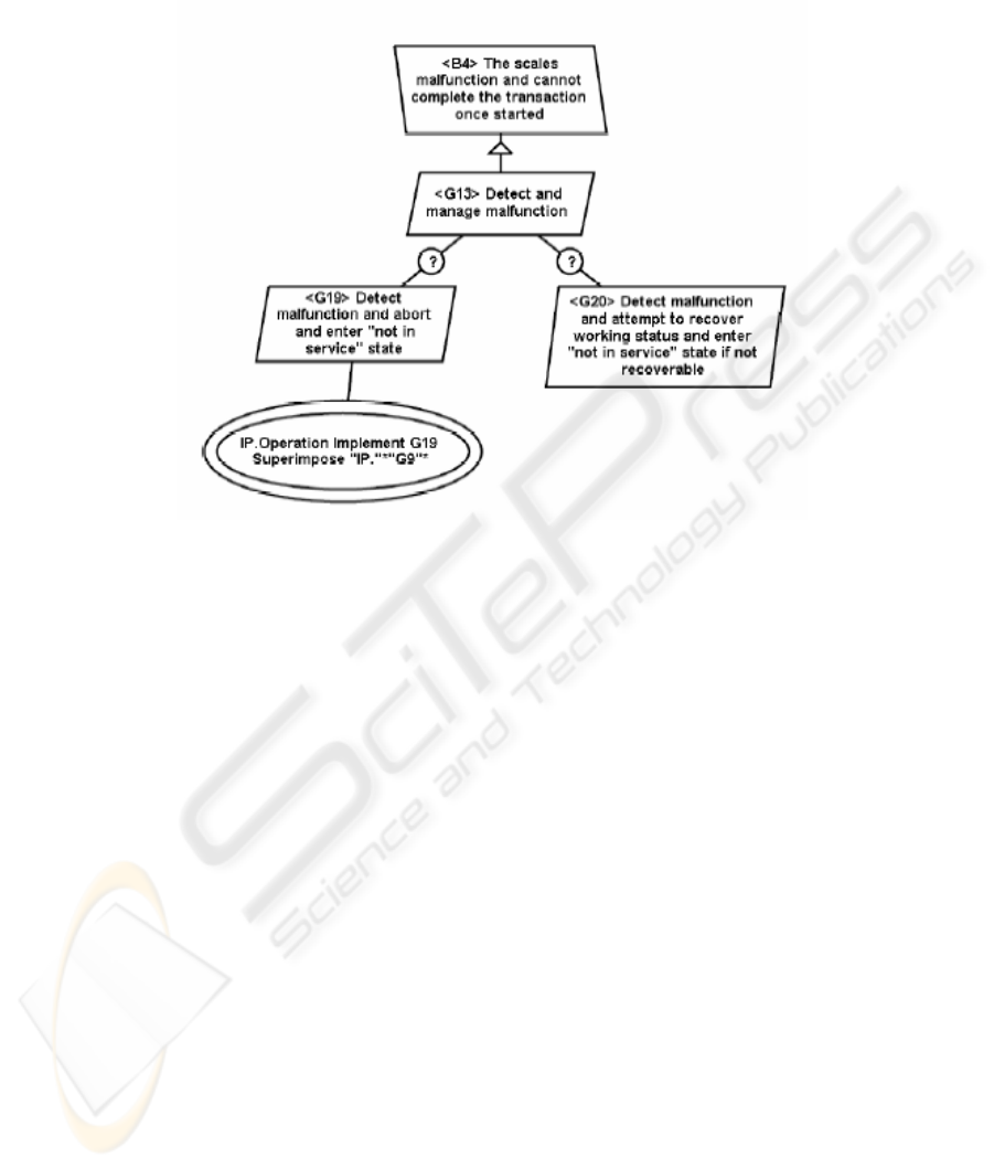
The operationalisation of G19 provides an example of a crosscutting process.
Fig. 7. Proposed resolution of obstruction B4 (showing strategic OR and crosscutting process)
The crosscutting process attached to G19 is interpreted as follows: The agent IP
will implement this operation and superimpose it on any operation that matches a
predicate. In this case, the predicate matches every process that is the responsibility of
agent IP and has in its title the string “G9”. Referring to Fig. 7, it can be seen that the
process operationalising goal G9 would be affected. If the goal analysis was complete
to the extent of operationalising all functional goals, some stakeholders might expect
this (anonymous) process to be superimposed on every functional process that
interfaces with a component that is expected to malfunction. This illustrates the kind
of misunderstanding about goals, obstacles and their resolutions that visualised goal
analysis can help to reveal and hence resolve.
Fig. 8 illustrates issues concerning assumptions and expectations. Assumptions that
the stakeholders need to validate include whether the payment is solely by a 1 Euro
coin. An expectation on the user is that they will pay and behave as instructed. These
are included in the summarizing graph Fig. 8.
The user expectation is not surprising. The assumption under the responsibility of
the stakeholders is crucial to the complexity of the system. Should this assumption be
invalid then the ramifications on cost and delivery times would need careful review
by the stakeholders.
Had the coin assumption been both overlooked and invalid a late and expensive
misunderstanding could have resulted. There may be other lurking assumptions with
even more potential for misunderstanding. For example, what are the assumptions
concerning use in public places?
46
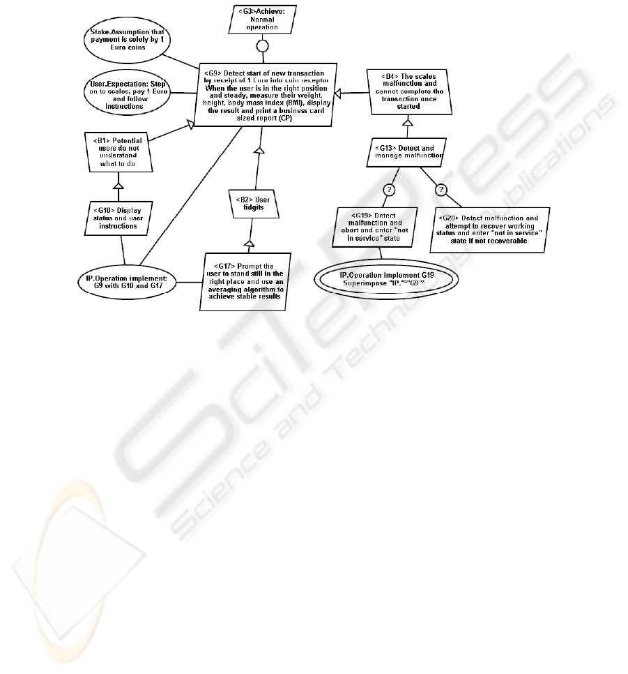
Fig. 8 shows a possible interpretation of the normal operation with its obstacles and
assumptions. It indicates hidden depths in the problem. These will be compounded
when the crosscutting effects of goals G2, G4 and G5 are added.
Fig. 8. Partial interpretation of normal operation including assumptions and expectations along
with strategic-or and crosscutting process
6 Discussion and Further Work
The work described here bears on various issues in software engineering practice and
research.
A practical issue that is particularly relevant to time-constrained projects is the
trade-off between allocating resources to goal analysis rather than, say, design or
coding. From an agile perspective, it may appear that it would be redundant to
elaborate a goal graph beyond an agreement between stakeholders on an initial set of
requirements and their acceptance tests. However, anecdotal evidence from our use of
KAOS Lite tends to contradict this position. We consistently find that an iterative and
interactive approach to goal analysis improves our understanding of a problem and
that we usually discard our initial attempts at drawing its goal graph. In particular, we
find that "lurking" obstacles and assumptions are more likely to be discovered by
discussion than by introspection, and that a provisional goal graph is a good device
for stimulating this process. The extended example in Section 4 illustrates this.
Nevertheless, we do not advocate that goal graphs must be elaborated to any
47

particular degree of completeness. We consider it more valuable for stakeholders to
clarify which paths in a goal graph lack detail, so that the risks of deferring further
elaboration can be considered.
These observations suggest that care is needed in designing tools to support goal
analysis. In broad terms, tools should only attempt to automate the tedious parts of
tasks, e.g. drawing symbols, importing text from other documents, checking graph
properties. The design of tools should not encourage the illusion that they can
magically discover knowledge. Tools should assist stakeholders in disclosing their
existing knowledge and discovering hidden but relevant information, within an active
process of dialogue and negotiation with each other. There are opportunities here to
learn from the insights of cognitive psychology and other disciplines in their
application to similar problem-solving situations such as pair programming.
A further reason for caution in automating goal analysis is that the decomposition
of goals for systems in real-world domains is properly expressed as semantic
entailment rather than equals or logical implication. Thus in Fig. 1:
GoalGGoalJGoalH
GoalAGoalBGoalC
=∨
=
∧
|
|
The use of the “entails” symbol |= reminds us that the stakeholders must take
responsibility for the validation of each entailment in a goal graph. It will rarely be
possible to automate this process.
The specification of the meta-model for KAOS Lite, particularly the treatment of
crosscutting concerns, touches on software engineering issues related to type checking
and responsibility-driven design. From a goal analysis perspective, an important
question is who decides whether a goal or process will be subject to superimposition
by other processes. This is currently an open question for KAOS Lite, and is itself an
example of potentially conflicting goals. On one side, it can be argued that a goal or
process should take responsibility for exposing itself to specific superimpositions, e.g.
by including an explicit clause in its declaration of the form "with Localization"
where Localization is a superimposing process defined elsewhere in the graph. This
approach would be similar to statically typed programming languages such as Scala
2
that support "mixin" classes and traits. Alternatively, it can be argued that a goal
graph is easier and quicker to draw if the scope of a superimposing process is defined
as a predicate in the properties of that process. In this case, the impact on other
processes is implicit. Usually, one would rely on the design tool to evaluate the
predicate and determine which processes will be superimposed on given the current
state of the graph. The analyst could check the correctness of a predicate by asking
the tool to visualise the impact of superimpositions. This approach would be
analogous to AspectJ
3
.
We originally devised KAOS Lite and the prototype tool that implements it to assist
our research into various aspects of software quality. Using KAOS Lite creates a
repository of information about “what is known about what is wanted” [3] that is
available from the earliest stages of a software project. We plan to use this resource
2
http://scala.epfl.ch/
3
http://eclipse.org/aspectj/
48

to inform our continuing work on profiling the quality of requirements. In particular,
the repository allows us to trace the provenance of requirements and assumptions
back to goals and their stakeholder owners, and to derive metrics about interesting
qualities of goal graphs. KAOS Lite also provides a test-bed for handling crosscutting
concerns and designing systems with rapidly evolving requirements.
7 Conclusion
Rigorous approaches to goal analysis are not appropriate for all software projects but
most projects can expect to benefit from clarifying stakeholders' goals. For example,
projects with innovative goals, diverse stakeholders, or in rapidly evolving domains
may be able to significantly reduce risks of failure by using goal analysis. Risk
mitigation should be easier, to both plan and justify, if stakeholders have a deeper
understanding of their goals and any conflicts between them. Nevertheless, in
practice, the greatest benefits of goal analysis may come from clearer foresight of the
obstacles to achieving goals, and raised visibility of the assumptions and expectations
that stakeholders are relying on for project success.
Thus goal analysis is not incompatible with time-constrained and agile approaches
to software development, provided that suitable tools are available. KAOS Lite is
work in progress towards satisfying this aspiration. It adopts the core concepts of the
KAOS method but simplifies the user interface. Its design principles are sympathetic
to agile perspectives. KAOS Lite aims to provide simple representations of simple
situations and to prevent bewildering complexity in complicated situations. The
treatment of crosscutting concerns as superimposed processes helps to avoid tangles
of criss-crossing graph edges. The simpler palette for representing processes should
encourage stakeholders to focus on agents' responsibilities, and to discourage
premature concern with design details. On the other hand, the palette for representing
strategic and policy decisions has been selectively enlarged to give higher visibility to
these issues and to clarify an ambiguity in interpretations of the OR connective
between sub-goals.
References
1. Antón, A.I., Potts, C. 1998. The Use of Goals to Surface Requirements for Evolving
Systems. Proceedings of the 20th International Conference on Software Engineering, Kyoto,
Japan 157-166
2. AspectJ: http://eclipse.org/aspectj
3. Boness, K., Harrison, R., Liu, K. 2005. Acknowledging the Implications of Requirements.
International Conference on Enterprise Information Systems
4. Cediti. A KAOS Tutorial. 2003. http://www.objectiver.com/en/documentation/
5. Clarke, S., Walker, R.J. 2001. Composition Patterns: An Approach to Designing Reusable
Aspects. Proceedings of the 23rd International Conference on Software Engineering,
Toronto, Ontario, Canada 5-14
6. Dardenne, A., van Lamsweerde, A., Fickas, S. 1993. Goal-Directed Requirements
Acquisition. Science of Computer Programming, Vol. 20. North Holland 3-50
49

7. Finkelstein, A., Bush, D. 2002. Environmental Scenarios and Requirements Stability.
Proceedings of the International Workshop on Principles of Software Evolution,
International Conference on Software Engineering,. ACM
8. Gilb, T. 1988. Principles of Software Engineering Management. Addison-Wesley
Professional
9. Kiczales, G., Lamping, J., Mendhekar, A., Maeda, C., Videira Lopes, C., Loingtier, J.-M.,
Irwin, J. 1997. Aspect-Oriented Programming. Proceedings of ECOOP
10. Kiczales, G., Hilsdale, E., Hugunin, J., Kersten, M., Palm, J., Griswold, W.G. 2001. An
Overview of AspectJ. Proceedings of ECOOP
11. Van Lamsweerde, A., Letier, E. 2003. From Object Orientation to Goal Orientation: A
Paradigm Shift for Requirements Engineering. In: Radical Innovations of Software and
Systems Engineering. Post-Workshop Proceedings of the Monterey 2002 Workshop,
Venice. Springer-Verlag LNCS
12. Yu, E. 1997. Towards Modelling and Reasoning Support for Early-Phase Requirements
Engineering, Proceedings of the 3rd IEEE International Symposium on Requirements
Engineering, Washington D.C., USA 226-235
50
