
DIAMOND : A Physical Multiagent Systems Codesign
Approach
Jean-Paul Jamont
1
and Michel Occello
2
1
Institut National Polytechnique de Grenoble, LCIS, 26000 Valence, France
2
Universit
´
e Pierre Mend
`
es, LCIS/INPG, 26000 Valence, France
Abstract. Multiagent systems are well suited to specify requirements for open
physical complex systems. However, up to now, no method allows to build soft-
ware/hardware hybrid multiagent systems. This paper presents an original method
for designing physical multiagent systems.
1 Introduction
Complex artificial cooperative physical systems are involved in application domains
as pervasive computing, intelligent distributed control or wireless computing. Physical
systems have a physical reality which does not apply only to the entities but also to the
environment in which they evolve. The system and its environment are strongly related.
In this context, the system elements integrate generally a software part and a hardware
part (electronic cards, sensors, effectors). The high dynamics, the great heterogeneity of
elements and the openess make a multiagent approach highly profitable for these artifi-
cial complex systems. But the existing multiagent design lifecycles have to be modified
to take into account software/hardware hybridation particularities.
This paper aims to present our approach called DIAMOND (Decentralized Iterative
Multiagent Open Networks Design) for the design of open multiagent physical complex
systems.
Our method can be qualified of codesign because it unifies the development of the
hardware part and the software part : the partitioning step is pushed back at the end
of the life cycle. A multiagent phase allows the management of collective features. A
component phase is used to design the elementary entities of the system (the agents)
and to facilitate the hardware/software partitioning. By lack of place in this paper, we
focus only on some steps of the method. They are described and illustrated through an
robotic design case study.
2 Overview of the DIAMOND method
Our iterative lifecycle. The DIAMOND method is built to design physical multia-
gent system. Four main stages, distributed on a spiral cycle (fig 1), may be distin-
guished within our physical multiagent design approach. The definition of needs defines
Jamont J. and Occello M. (2005).
DIAMOND : A Physical Multiagent Systems Codesign Approach.
In Proceedings of the 1st International Workshop on Multi-Agent Robotic Systems, pages 177-182
DOI: 10.5220/0001195901770182
Copyright
c
SciTePress
what the user needs and characterizes the global functionalities. The second stage is a
multiagent-oriented analysis which consists in decomposing a problem in a multiagent
solution. The third stage of our method starts with a generic design which aims to build
the multiagent system, once one knows what agents have to do without distinguishing
hardware/software parts. Finaly, the implementation stage consists in partitioning the
system in a hardware part and a software part to produce the code and the hardware
synthesis.
Fig.1. Our lifecyle
Most existing multiagent methods usually distinguish only analysis and design phases
[1]. Very few methods deal with other phases. We can find for example a deployment
phase in MASSIVE [4] or Vowels [5]. This deployment phase takes in our particular
field a great importance since it includes the hardware/software partitioning. To cover
the whole lifecycle, different formalisms are required to express different things at dif-
ferent levels [2], for this reason we adopt a lifecycle using four stages mixing different
expressions using more or less formal paradigms and languages (agents, components,
Finite State Machines, Hardware Definition Languages). The most current lifecycle
used in multiagent methods is the classical cascade lifecycle.
A last and major difference between DIAMOND and other multiagents approach
is, as said previously, that DIAMOND unifies the development of the hardware part
and the software part. In a traditional system design, the partitioning step stands at the
beginning. In fact, a hardware requirement and a software requirement are created from
the system requirement. The software part of the system is built using a multiagent
method and its associated lifecycle.
The case study. To illustrate the various phases and activities of our method, we
will use a case study dealing with robotic design. To make the illustration easily under-

standable, we will adopt simplified system requirements. The experimental conditions
are inspired by [3]. Robots evolve on a football field. A video recorder system makes it
possible to know the position of each robot as well as of the ball. These positions are
periodically broadcasted to all robots. If the ball goes out of the limits of the field, a
robot of the nonfaulty team recovers the ball and plays (the order is given by the ref-
eree). If a robot has no more battery or is dysfunctioning, the match is stopped (the
order is given by referee for human safety reason) and the robot is withdrawn from the
field: all robots must be then motionless. At the beginning of a match the robots must
be located in their camp and the referee decides to give the gardian role to one robot of
each team. So, the game is open and the team, which marks the higher number of goals
in 90 minutes, wins.
3 Definition of needs
This preliminary stage begins by analysing the physical context of the system (identify-
ing workflow, main tasks, etc...). Then, we study the different actors and their participa-
tive user cases (using UML use case diagrams), the services requirements (using UML
sequence diagram) of these actors.
The second step consists in the study of the modes of steps and stops. This activity
is very significant because it enable to structure the global running of the system. It is
generally wishable that the system functions in autonomy. But working with physical
systems imposes to know all the other possible behaviors precisely when the system
starts, when it goes under maintenance etc.
This activity puts forward a restricted running of the system. It allows to specify the
first elements necessary for a minimal fault-tolerance. Moreover, it enable to identify
cooperative (or not) situations and to define recognition states in order to analyse, for
example, the self-organizational process of an application. This activity allows to take
into account the safety of the physical integrity of the users possibly plunged in the
physical system.
We have defined 15 differents modes that we regroup in 3 families. The stops modes
which are related to the different procedures for stopping and to define associate recog-
nition states. The steps modes which focuses on the definition of the recognition states
of normal functionning, test procedures etc. The failing operations modes which con-
centrates the procedure allowing to a human maintenance team to work in the system
or to specify rules for restricted running.
Application to our case study. We find the following actors. The referee (logical actor)
manages match parameters (choice of a goalkeeper and a camp for each team, verifica-
tion that robots respect the rules) and authorise the human to withdraw a robot when all
robots are motionless. The manager (physical actor) withdraws robot when a problem
occurs. The ball (physical actor) moves under the robot actions. The opposing team
(physical/logical actor) shares the field with us. The camera system broadcasts the co-
ordinate of each robot and of the ball.
There is two user cases. The configuration expresses that the referee chooses a field and

a goalkeeper for each team. This user case triggers another one : the game opening the
game. For our application, the identified modes are:
1. Modes of stops: Two modes of stops must be characterized: other modes are not
exploited.
– Idle: In a idle mode, the robots must be motionless.
– Stops requested on normal mode : when a robot dysfunction occurs, the referee
can decide to freeze the game.
2. Modes of steps:
– Normal mode: in this mode all the robots must answer to the referee requests,
there is no emergency stop.
– Mode of preparation: during the preparation phase the robots are positioned
on the ground. Robots should neither move nor use their actuators. This mode
ends when the parameters setting period starts.
– Mode of test: one can want to calibrate the maximum power for shooting.
3. Failing modes: only the management of the emergency stop is relevant in our ap-
plication.
– Mode of stop aiming to ensure the safety: If an emergency stop is activated,
robots do not have the right to move or use their effectors.
4 Multiagent-oriented analysis
The multiagent stage is handled in a concurrent manner at two different levels. At the
society level, the multiagent system is considered as a whole. At the individual level,
the system’s agents are built. This integrated multiagent design procedure encompasses
five main phases discussed in the following.
Application to our case study : situation phase. Each robot can know its geographical
position, the position of the ball and of the other robots. Dimensions of the ground are
known and the field of each team is communicated at the beginning of each part. The
positions of each robot can be memorized at different dates to estimate displacements,
directions of the robots and their trajectories. The trajectory of the ball obeys to physical
law. Agent can estimate this trajectory and act on it.
The active entities are the robot-players. The ball is a passive entity which obeys to
agent action (shooting) by a displacement according to the physic laws.
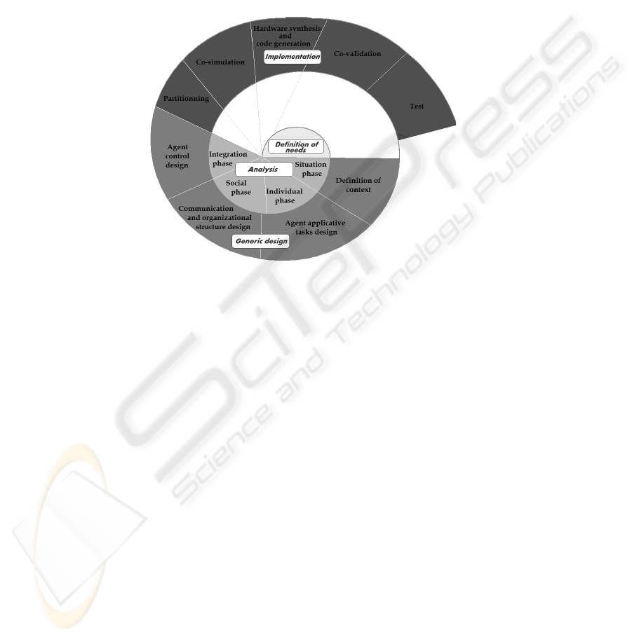
Application to our case study : Individual phase. The agent world representation
consists in a collection of triplets (id,x,y) and in the field dimension.
In our application, robot players are modeled by agents. Their individual capabilities
can be specified using a tree to show the different action levels.
We specify the agent context with a context diagram (see fig 3).
After one iteration to take into account the society phase, individual behaviors are
implemented using finite state machine. We can define an agent with a goalkeeper be-
havior. Other agent can alternate two differents behaviors (shooter or defender). For
example, the goalkeeper behavior define that the agent must always to be on a possible
trajectory of shooting.
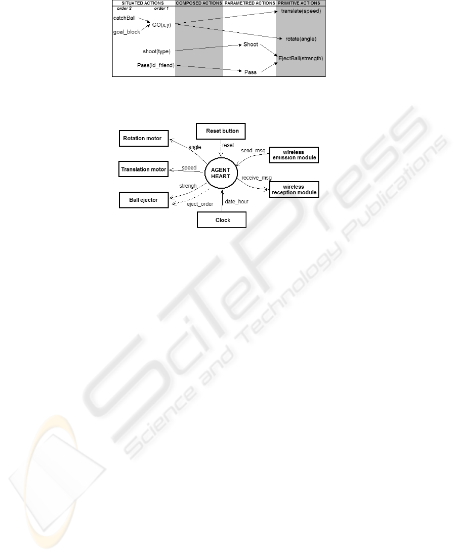
Fig.2. Actions scheme
Fig.3. Context diagram
Application to our case study : Society phase. Representation of others: The other
players positions can be known by the capture of information from the video system
(WIFI module). Their directions can be estimated if agent can memorize the previous
positions. The friend intention can be announced.
Interactions between the agents are carried out by exchange of messages. An agent
must be able to communicate with its team to diffuse its intention. It can use a peer-to-
peer communication to solve a conflict or to choose a trajectory with a friend.
Collaborative actions can be instantiated : a player can request the ball when it has
an occasion of shooting. It can ask somebody to change position to attract an opponent
elsewhere.
Organization. A TEAM according to the requirement is composed of a goalkeeper
and three other agents which can be SHOOTER or DEFENDER.
Collective behavior. As seen previoulsy, finite state machines can implemented col-
lective behavior.
Application to our case study : Integration phase. We illustrate this phase with two
examples.
Influence 1: If agent wants to move to a point, somebody (friend or not) can be on its
trajectory.
Correction 1: If the agent on the trajectory is a friend, the agent owning the ball has the

priority.
Influence 2: Two agents request the ball for shooting.
Correction 2: Agent use an election protocol (they exchange an estimation of their
sucess probabilities).
5 Conclusion
We work currently on the tool associated with the method that we propose. It is created
using the Java language. The part which relates to the creation of agents creation with
components, manual partitioning and automatic generation of code are operationnal.
This work proposes some innovative contributions in term of hybrid software/physical
multiagent lifecycle. It proposes components used as tools for integration, allowing
software or hardware derivation. Components are thus used in this approach as units of
implementation but further as unit of design allowing the assembly.
Our future work concerns the MASC tools (MultiAgent System Codesign) associ-
ated with the DIAMOND method.
References
1. Scott A. DeLoach, Mark F. Wood, and Clint H. Sparkman. Multiagent systems engineering.
International Journal of Software engineering and Knowledge Engineering, 11(3):231–258,
2001.
2. Daniela E. Herlea, Catholijn M. Jonker, Jan Treur, and Niek J. E. Wijngaards. Specification of
behavioural requirements within compositional multi-agent system design. In LNCS, volume
1647, pages 8–27. Springer-Verlag, 1999.
3. H.-P. Huang, C.-C. Liang, and C.-W. Lin. Construction and soccer dynamics analysis for an
integrated multi-agent soccer robot system. In Natl. Sci. Counc. ROC(A), volume 25, pages
84–93, 2001.
4. J. Lind. Interative Software Engineering for multiagent systems: The MASSIVE Method, vol-
ume 1994 of LNCS/LNAI. Springer Verlag, 2001.
5. P.-M. Ricordel and Y. Demazeau. From analysis to deployment: A multi-agent platform sur-
vey. In Proceedings of the First International Workshop on Engineering Societies in the Agent
World, pages 93–105, London, UK, 2000. Springer-Verlag.
