
TELE-ROBOTS WITH SHARED AUTONOMY:
TELE-PRESENCE FOR HIGH LEVEL OPERABILITY
Thomas Geerinck, Valentin Enescu, Alexandru Salomie, Sid Ahmed Berrabah, Kenny Cauwerts,
Hichem Sahli
Electronics and Information Processing Department (ETRO)
Vrije Universiteit Brussel, Pleinlaan 2, 1050 Brussels, Belgium
Keywords: tele-robotics, tele-operation, shared autonomy, tele-presence.
Abstract: The aim is to improve the operability of an advanced demonstration platform incorporating reflexive tele-
operated control concepts developed on a mobile robot system. The robot is capable of autonomously
navigating in semi-structured environments. Reflexive tele-operation mode employs the robot extensive
onboard sensor suite to prevent collisions with obstacles when the human operator assumes control and
remotely drives the robot to investigate a situation of interest. For the shared autonomy aspect, four levels of
autonomy have been implemented: tele-operation, safe mode, shared autonomy and autonomous mode. The
operability level is enhanced by improving significantly the situational awareness of the operator by using
an inertial tracker in combination with a head mounted display creating a certain feeling of presence. As
such, the system permits precision observation and pinpoint data collection without subjecting the user to a
possibly hazardous remote environment.
1 INTRODUCTION
The design of a mobile robot capable of performing
a complex task autonomously, even if it operates in
well-structured environments, requires the
integration of different technologies. Important
aspects are the mechanical design, the low-level
electronic control, perception of the environment
using different sensors including cameras, sensor
fusion, efficient path planning, and intelligent robot
control.
Tele-robotics, tele-presence, tele-manipulation,
tele-operation, tele-service are all terms that describe
ways of handling machines and materials remotely.
The term tele-operation refers simply to the
operation of a vehicle or system over a distance
(Fong et al, 2001). Traditionally, tele-operation is
divided into direct tele-operation and supervisory
control (Sheridan, 1992). In direct tele-operation the
operator closes all the control loops himself. In
between autonomous robots and direct tele-
operation, levels of supervised or shared autonomy
(control) can be created. Depending on the degree
the human operator is directly involved to the robot
control, some variables or functions are supervised
and some are controlled directly by the operator.
It is generally accepted that a more efficient
achievement of the task can be obtained by
increasing the number of data feedback and by using
proper multimedia interfaces (Diolaiti et al, 2002).
However, the need for the operator effort decreases
the autonomy of the robot (Scholtz et al, 2003)
(Yanco et al, 2004) and increases the operator load
and the transferred amount of information between
the operator and the robot. Poorly designed user
interfaces, on the other hand, can result in spatial
disorientation, lack of situational awareness,
confusion, and frustration (Olivares et al, 2003). The
human-machine interface must be designed so that it
maximises information transfer while minimising
cognitive load (Meier et al, 1999). One good
approach to enhance the quality of information
available to the operator is the use of sensor fusion
to efficiently display multisensor data.
Step-by-step, the tele-operation technology
improves towards tele-presence based technology by
increasing the sensory feedback, using HMDs, head
motion trackers, datagloves, etc. (Tachi et al, 1989).
Tele-presence means that the operator receives
sufficient information about the robot and the task
243
Geerinck T., Enescu V., Salomie A., Ahmed Berrabah S., Cauwerts K. and Sahli H. (2005).
TELE-ROBOTS WITH SHARED AUTONOMY: TELE-PRESENCE FOR HIGH LEVEL OPERABILITY.
In Proceedings of the Second International Conference on Informatics in Control, Automation and Robotics - Robotics and Automation, pages 243-250
DOI: 10.5220/0001184302430250
Copyright
c
SciTePress
environment, displayed in a sufficiently natural way,
that the operator feels physically present at the
remote site (Sheridan, 1992). The optimal degree of
immersion required to accomplish a task is still a
topic for discussion. Some researchers claim that
high-fidelity tele-presence or tele-existence (Tachi,
2003) requires feedback using multiple modalities
(visual, auditory, haptic) (Meier et al, 1999). The
most important feedback provider remains the visual
system mounted on the robot. A more human
viewpoint is created by using stereovision. Vision is
the sensor which is able to give the information
“what" and “where" for the objects a robot is likely
to encounter most completely.
Furthermore, a distinction can be made between a
passive and an active vision system (Davison, 1998).
Humans are most certainly in possession of an active
vision system. Translated to the robot, this implies
the need of zoom function and a manual or
automatic tracking system on the vision system of
the robot. Active vision can be thought of as a more
task driven approach than passive vision. With a
particular goal in mind for a robot system, an active
sensor is able to select from the available
information only that which is directly relevant to a
solution, whereas a passive system processes all of
the data to construct a global picture before making
decisions. In this sense it can be described as data
driven.
These approaches work fine when there is little
delay in communication, however once transmission
delay is introduced the systems become unstable.
The instability problem can be eliminated by shared
(supervisory) control. Under shared control the
operator gives a goal to the tele-robot. The goal is
then executed by a local control system and
supervised by the operator. This emerging field of
Human-Robot Interaction (HRI) represents an
interdisciplinary effort that addresses the need to
integrate human factors, cognitive science and
usability concepts into the design and development
of robotic technology. As the physical capabilities of
robots improve, the reality of using them in
everyday locations such as offices, factories, homes
and hospitals, as well as in more technical
environments such as space stations, distant planets,
mines, ocean floors and battlefields, is quickly
becoming more feasible (Yanco et al, 2002).
Generally speaking, robots are more adept at
making some decisions by themselves than others
(Scholtz, 2003). Unstructured decision making,
however, remains the domain of humans, especially
whenever common sense is required. In order for
robots to perform better, therefore, they need to be
able to take advantage of human skills (perception,
cognition, etc.) and to benefit from human advice
and expertise. To do this, robots need to function not
as passive tools, but rather as active partners.
Numerous robot control architectures have
addressed the problem of mixing humans with
robots. Systems like adjustable autonomy, mixed
initiative systems (Marble et al, 2004) and
collaborative control (Fong, 2001) (Fong et al, 2002)
have recently received considerable research
attention. As an example of adjustable autonomy
obstacle avoidance behaviour (Borenstein, 1990) can
be considered.
The main contributions of this paper lie in
presenting a functionality scheme of the global
system, incorporating the mentioned state of the art
hardware devices and software algorithms. This way
an advanced demonstration platform is created, ideal
for further enhancements in the area of mobile
robotic research.
The remainder of this paper is organized as
follows. First, an overview of the system
architecture is given (Figures 1 and 2), explaining all
the co-existing modules, starting from hardware
level, containing the physical units used in this
project, through implementation and task description
level up to the programming environment level,
where different threads arise and form the modules.
Then in the discussion some results are given, before
necessary conclusions are drawn.
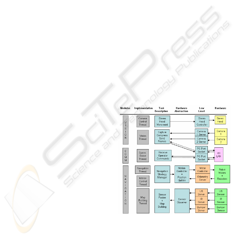
Figure 1: Robot system architecture
2 SYSTEM OVERVIEW
The overview of the system is presented in Figure 1,
the robot site, and Figure 2, the client or operator
ICINCO 2005 - ROBOTICS AND AUTOMATION
244
site. In order to structure this description, first,
traditional or direct tele-operation will be the task to
achieve, including the creation of feeling of
presence. All the indispensable modules will be
briefly explained. To introduce supervisory or
shared autonomy control, additional units must be
added. These will be presented subsequently.
In order to introduce shared or supervisory
autonomy control aspects to the existing architecture
of direct tele-operation, a choice must be made in
how to define the responsibilities for both robot and
tele-operator. We chose to provide fixed static
responsibilities for human and robot. Based on the
statement that the aim of robotics is to serve and
help humans, our implemented system is well-suited
for exploring purposes. The fixed responsibilities are
defined in 4 levels of autonomy:
• Tele-operation: The user has full, continuous
control of the robot at low level. The robot takes
no initiative except perhaps to stop once it
recognizes that communications have failed. It
does indicate the detection of obstacles in its path
to the user, but will not prevent collision. This is
the default autonomy level.
• Safe Mode: The user directs the movements of
the robot, but the robot takes initiative and has
the authority to protect itself. For example, it will
stop before it collides with an obstacle, which it
detects via multiple US and IR sensors.
• Shared Control: The robot takes the initiative to
choose its own path in response to general
direction and speed input from the operator.
Although the robot handles the low level
navigation and obstacle avoidance, the user
supplies intermittent input to guide the robot in
general directions.
• Full Autonomy: The robot performs global path
planning to select its own routes, acquiring no
operator input. The goal of the robot can be
specified by the operator or by the robot’s vision
system.
Figure 2: Client or operator system architecture
A. Tele-operation
Robot Navigation Module
The green boxes (Figure 1) represent robot devices.
The robotic platform is the Nomad200 (Figure 3), an
electrical driven mobile robot build by the Nomadic
Technologies, Inc. company. Build at early 90's; it
has now reached the status of a somewhat antiquated
machine in world of robotics. It is equipped with
three sensory modules: ultrasonic,
infrared and tactile. With its strong and stable
structure, the Nomad200 provides an ideal platform
for adding extra mechanical and/or sensory
structures. The red boxes are taken care of by the
internal computer system of the Nomad robot.
In direct tele-operation, the navigation module
has several tasks: communication with the robot,
building a map of the environment, and manage the
strategy of navigation. These tasks, blue coloured in
Figure 1, have been implemented in another PC
platform (Figure 3), placed on top of the Nomad200
and described further on. A coax cabled ethernet
connection links both systems.
The navigation strategy manager selects which
driving behaviour is executed. For direct tele-
operation, this behaviour is straightforward: simply
feed the acquired speed and steering commands to
the robot’s motion controller.
For direct tele-operation the building of a map of
the robot’s local environment is not indispensable.
However, it is useful for development purposes. The
map is constructed combining the US and IR
sensory information.
Robot Communication Module
The robot is equipped with a wireless
receiver/transmitter (802.11g/2.4GHz Wireless PCI
Adapter) to achieve communication with a remote
user. Using two socket based connections two tasks
have to be accomplished in this module. Receiving
the remote operator’s input commands and sending
back an acknowledgment message is the first task.
Subsequently the sending of the camera frames
when received a proper command.
TELE-ROBOTS WITH SHARED AUTONOMY: TELE-PRESENCE FOR HIGH LEVEL OPERABILITY
245
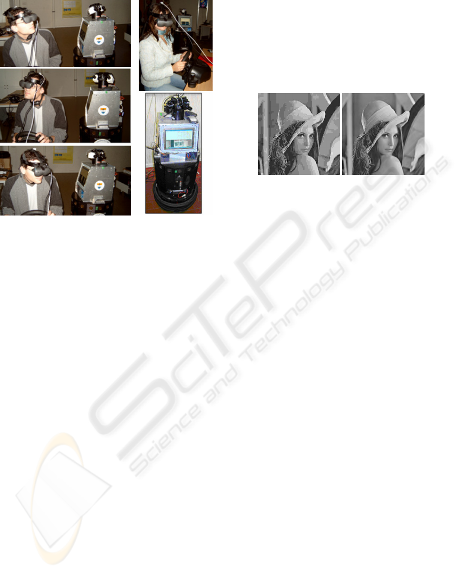
Figure 3: The Nomad200 robot with the upper PC-
platform and the biclops head on top. The stereo vision
system forms the robot’s eyes
Robot Vision Module
The robot vision module consists at the hardware
level of a stereo head, type Biclops, and two
miniature CCD Color Cameras. The head is
mounted on the upper PC platform, carrying both
cameras (Figure 3).
This module performs two tasks concurrently,
namely, (1) to accurately control the pan and tilt
angle of the stereo head to allow seamless changing
the viewpoint, and (2) to capture in a synchronized
way frames from the left and right cameras by
means of a well suited frame grabber. Further, the
captured frames are sent to the remote user. In order
to reduce the time needed for the transfer the frames
are compressed either using the classical JPEG
encoder or a Wavelet based coding technique.
The employed Wavelet based coding scheme, i.e.
SQuare Partitioning (SQP) (Munteanu et al, 1999)
was developed at our department. It allows rate-
distortion performances comparable with state-of-
the art encoding techniques, allowing lossy-to-
lossless reconstruction and resolution scalability. As
illustrated in Figure 4, which shows a side-by-side
visual comparison of a frame compressed at 45:1
with JPEG and SQP, SQP clearly outperforms JPEG
in terms of rate-distortion. Although the encoding
with SQP is roughly 4 times slower than with JPEG,
still a CIF image can be compressed in real-time at
25 frames per second on a 2Ghz processor.
The compressed frames are handed to the
communication module that further sends them via
the wireless link to the client. The resolution
scalability feature of SQP comes in handy when
progressively streaming the data, since the decoder
at the client site does not need to wait until all the
data has arrived, but it may start reconstructing a
lower resolution of the image (from the received
data) and start processing that image first while
waiting to receive the remaining data that would
allow to reconstruct the image at full resolution.
JPEG, CR=45 SQP, CR=45
Figure 4: Image was compressed at 45:1 with JPEG and
SQP
Client Control Module
The main task of this module is the regular update of
input commands conferred by the operator. By
means of two hardware devices the operator controls
the robot and the stereo head. The robot is controlled
by use of a joystick, which is interfaced using Direct
Input. The stereo head is controlled by movement of
the operator’s head. A motion tracking device is
placed on the head of the operator and registers the
rotations of the head made by the operator. The
InertiaCube from InterSense is a precision
orientation reference system and performs an
inertial-based tracking from integration of 9 sensing
elements. The range of this device is 360° and has an
update rate of 180 Hz. It has 3 DOF (Yaw, Pitch and
Roll). However, only 2 of them are actually used,
according to the 2 DOF of the pan-tilt stereo head.
The range of the pan-tilt stereo head is also limited:
120° of tilt range, 240° of pan range.
Whenever the update of input commands is done
and the user interface is updated, this new data is
send to the robot, via the previously mentioned
socket based connection.
Client Communication Module
The client’s computer is equipped with a
802.11g/2.4GHz Wireless Broadband Router.
According to the robot’s communication setup also
here 2 socket objects are attached to 2 different ports
of the PC.
Client Active Vision Module
The received compressed images from the robot’s
eyes, are of course decompressed, before they fill
the buffers of a NVIDIA Quadrox graphical card.
ICINCO 2005 - ROBOTICS AND AUTOMATION
246
The operator sees a 3D view of the robot’s
environment, due to the stereovision setup. Being
able to look around freely, from a remote location, at
a sufficiently high frame rate, due to image
compression, provides the operator with a certain
feeling of presence at the remote site.
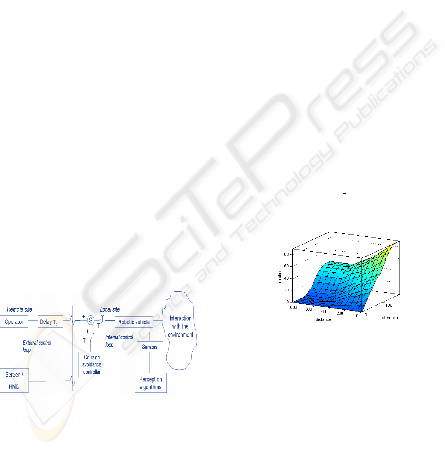
B. Shared Autonomy Control
The addition of the mentioned levels of autonomy
implicates changes to the existing modules. In this
section these implications to the existing tele-
operation modules are discussed in detail.
Robot Navigation Module
According to the selected level of autonomy, the
navigation strategy controller selects the proper
robot behaviour. In safe mode the available map is
checked for collision danger and if necessary a
emergency stop is performed. In shared control
mode as well as in autonomous mode the robot has
the responsibility of the local navigation. To
accomplish this task an obstacle avoidance
controller is included in the system. As shown in
Figure 5 the output from the obstacle avoidance
controller is combined with the input direction from
the operator.
This combining should be seen as a weighted sum of
two vectors:
• the operator's reference command F
t
• the obstacle avoidance feedback F
r
generated
by the autonomous obstacle avoidance
algorithm.
rrtts
FwFwF
G
G
G
⋅+⋅=
Re
1=+
rt
ww
),,(
321 obstacleobstacleobstacler
dddfw =
Figure 5: Obstacle avoidance control architecture.
The steering of the robot is aligned with the
direction of the resultant vector F
Res
and yields
continuous and smooth motion. In the absence of
obstacles, F
r
= 0, the robot follows the operator's
directions. If the robot approaches an obstacle, F
r
(usually pointing away from the object) and w
r
gradually increase in magnitude and cause a
progressive avoidance manoeuvre. This gradual shift
in control is completely transparent.
The basic building block of the present
navigation strategy is a behaviour, defined here as a
representation of a specific sequence of actions
aimed at attaining a given desired objective. Each
behaviour comprises a set of fuzzy-logic rules.
The present robot-navigation strategy involves
four behaviours, denoted seek-goal, avoid-obstacle,
go straight ahead, and make U-turn. These
behaviours are described in detail in the following.
Goal seeking behaviour
This controller allows the mobile robot, starting
from the actual position, to reach a target point. This
operation is realised in an environment where there
are no obstacles around the robot.
Given the azimuth (ϕ) and the range to the target
(ρ), a fuzzy controller calculates the turn angle and
speed commands to apply to the robot to reach it.
The used controller is of zero order Sugeno’s type
and uses linguistic decision rules of the form:
If (ρ is A
i
) and (ϕ is B
i
) then (∆θ is C
i
)
Where A
i
and B
i
are fuzzy sets defined
respectively in ρ and ϕ universes of discourse, and
C
i
is a constant.
In this controller (Figure 6)
the change in angle to
apply to the robot to reach the target increases as ϕ
and ρ decreases, i.e. as the target is closer to the
robot and far from its direction.
Figure 6: Transfer function of the controller for Goal
seeking
Obstacle Avoidance
If an obstacle is detected in front of the robot, the
nearest point (of this obstacle) to the robot and
making the smallest angle (azimuth) with its axis is
marked.
A fuzzy controller using the information
provided by the sensors is initiated. It considers the
polar coordinates in the robot frame of the detected
points from the obstacles to estimate the change in
angle to apply to the robot to avoid these obstacles.
The used controller is a zero order Sugeno’s type
too and its transfer function is given by Figure 7. In
TELE-ROBOTS WITH SHARED AUTONOMY: TELE-PRESENCE FOR HIGH LEVEL OPERABILITY
247

this controller the change in angle to apply to the
robot is more important as the obstacle is closer to
the robot and closing its way.
Figure 7: Transfer function of the controller OAC
Go straight ahead behaviour
This action is used by the robot if there is an
obstacle embarrassing it to go toward its goal but no
obstacle is detected in front of it. In this case the
robot continues moving with its currents speed and
orientation.
Make U-turn behaviour
The robot uses this action in order to leave some
blockage situations like a closed way or a narrow
way. When this action is activated, the robot makes
a U-turn in its position and moves straight ahead
until a rotation at the right or at the left is possible.
Robot Vision Module
In all control modes the operator selects a certain
goal or location of interest based on the the visual
feedback information received from the robot. The
human in the control loop is fully responsible for
this goal selection using his own capabilities for
active visual search tasks. However, one could think
of merging this target choice towards the robot.
Therefore biologically inspired visual attention
models must be considered for the automated
selection of a region of interest, combined with
tracking algorithms to keep the target in the field of
view. Yet, research must be done to allow useful
cooperation between robot visual actions and human
visual actions.
3 DISCUSSION
Tele-operation performance
The performance of control and visual feedback
loops are essential when the performance of the tele-
operation system is evaluated. The tele-operation
system in the test platform is coordinated, i.e. the
position of steering and throttle is transferred to the
position of those actuators. When the actuators are
speed controlled servos the position control loops
are made in the robot’s main computer.
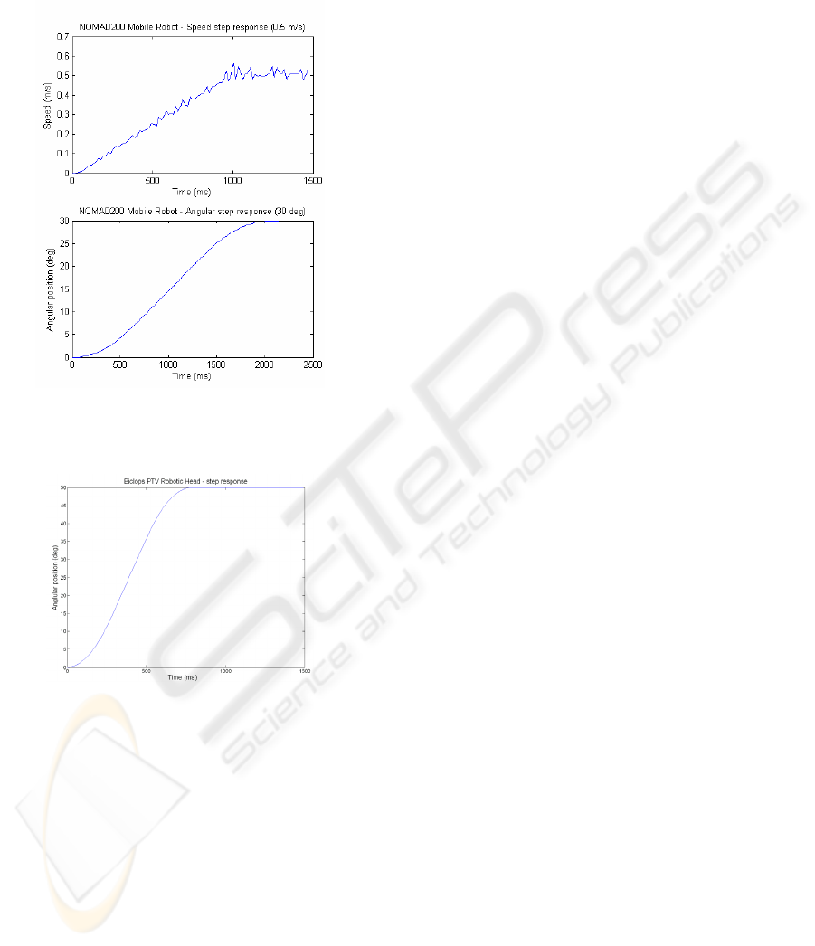
Performance of the test vehicle was examined by
measuring the step responses of the steering and
throttle over the tele-operation loop, ignoring the
time delay in this ideal communication test case. The
steering and throttle step responses are given in
Figure 8. It can be seen that the steering has a
relatively big delay, about 2 s. Also the throttle’s
delay is quite big before reaching the desired speed,
300 ms. Compared to the mean human reaction time,
the speed delay is acceptable. The steering delay
however, makes the operator wait for the robot’s
accurate reaction. To create a reactive system the
update frequency of the data is 10 Hz.
The delay in communication is not a constant
value. It depends on the distance between router and
antenna, and the obstacles in between, e.g. wall of
room. However, most of the delay comes from the
slowness of the actuators.
The vision loop consists of two processes. First of
all the motion-head-tracking-servo-head loop
provides some delay (Figure 9: 600ms/50dgr)
mainly caused by the servo system. Internally the
update rate of the head motion occurs at 180 Hz. The
update of these angles to the robot occurs every 100
ms (10 Hz), again to keep this system reactive.
The loop of capturing, compressing and sending
stereo images contains two delays. The first delay is
the time it takes to compress and decompress, the
second is the transmission delay. The time lost with
compression and decompression is on the other hand
recuperated by the much faster transmission of the
images compared to the case without compression.
The resolution of the camera is 384 by 288, resulting
in a image with size 300Kb, and an obtained frame
rate of approximately 5Hz without compression.
This is obviously too low to provide good and
smooth view of the environment. When using
compression a frame rate of approximately 20 Hz is
obtained. This augmentation in frame rate is limited
by inherent limited processing capacity of the PC.
Feeling of presence: tele-presence
A general problem when applying augmented tele-
presence systems are technical complexity and the
need for broad bandwidth for data transmission. Use
of image compression partly solves this bandwidth
issue. When wireless communication is the only
choice, the cost of the data transmission system for
long distances can be very high. For the simulation
of the human active vision system at robot’s site, a
complex servo system for cameras should have up to
7 DOFs if all head and eye movements were to be
tracked and repeated. In practical applications,
mostly due to cost and fault probability, the
minimum number of DOFs which is still acceptable
from the operator point of view is 2.
ICINCO 2005 - ROBOTICS AND AUTOMATION
248
Ergonomic problems are not minor and need a
careful consideration. The problem of simulator
sickness (SS) can be significant in tele-presence
based tele-operation. The most typical reason is the
Figure 8: Speed and angular step response from the
Nomad200 robot platform
Figure 9: Biclops robotic head step response
cue conflict. In cue conflict different nerves get
different information from the environment. Typical
here is the conflict between visual and vestibular
inputs. Other possible reasons can be the resolution
of the HMD and the time lags in vision and control
resulting in motion blur and a significant decrease of
situational awareness. In our system the resolution
of the HMD is 800x600 pixels.
Nevertheless, the feeling of presence remains a
highly subjective feeling. It is very difficult to
design good experiments from which meaningful
conclusions can be drawn. It is our believe that a
good combination of feedback modalities can
provide a sufficient feeling of presence for exploring
and surveillance purposes. The HMD provides the
operator good quality images, thanks to state of the
art compression, at a sufficiently high frame rate, to
obtain a smooth view of the environment. Also the
stereo vision system provides the operator with a
notion of depth, giving him the ability to perceive
absolute distances. In order to be constantly aware of
the motion of the robot, a layer is placed upon the
images in the HMD with the speed, steer angle, and
pan and tilt angle. The one thing that is currently
missing from the setup is a auditory feedback
modality, providing the operator with stereo sounds
from the remote environment as well as robot
messages about his own status. This additional
modality will be added in the near future.
4 CONCLUSION
In this paper, an advanced mobile robot platform is
presented, which can be used for exploring and
surveillance purposes. At present a manual control
system by the human operator using a joystick has
been developed. In order to reduce the operator’s
workload related to the robot’s control, we
introduced shared autonomy principles by defining
several levels of autonomy. An obstacle avoidance
algorithm was implemented based on fuzzy logic,
giving the robot the responsibility of the local
navigation.
The current stereo vision system allows the
human operator not only to feel that they are located
at the remote task area, but also to catch a sense of
distance to the objects existing in the environment.
This is accomplished by integrating different
technologies, such as image compression, wireless
communication, head motion tracking, etc.
ACKNOWLEDGEMENT
This research has been conducted within the
framework of the Inter-Universitary Attraction-Poles
program number IAP 5/06 Advanced Mechatronic
Systems, funded by the Belgian Federal Office for
Scientific, Technical and Cultural Affairs.
REFERENCES
Fong, T., Thorpe, C., 2001, Vehicle teleoperation
interfaces, Autonomous Robots, Vol. 11, No. 1, July.
Sheridan, T.B., 1992, Telerobotics, Automation, and
Human Supervisory Control, The MIT Press.
Diolaiti, N., Melchiorri, C., 2002, Tele-Operation of a
Mobile Robot Through Haptic Feedback. IEEE Int.
TELE-ROBOTS WITH SHARED AUTONOMY: TELE-PRESENCE FOR HIGH LEVEL OPERABILITY
249

Workshop on Haptic Virtual Environments and Their
Applications, Ottawa, Ontario, Canada, 17-18
November 2002
Scholtz, J., Antonishek, B., Young, J., 2003, Evaluation of
Operator Interventions in Autonomous Off-road
Driving, Proceedings of the NIST Performance
Metrics for Intelligent Systems Workshop,
Gaithersburg, MD, USA, September 16-18
Yanco, H.A., Drury, J.L., Scholtz, J., 2004, Beyond
Usability Evaluation: Analysis of Human-Robot
Interaction at a Major Robotics Competition, To
appear in the Journal of Human-Computer Interaction.
Olivares, R., Chen, Z., Bodenheimer, B., Adams, J.A.,
2003, Interface Evaluation for Mobile Robot
Teleoperation. Nashville USA, Vanderbilt University.
Meier, R., Fong, T., Thorpe, C., Baur, C., 1999, A Sensor
Fusion Based User Interface for Vehicle
Teleoperation. S.l., S.e.
Tachi, S., Arai, H., Maeda, T., 1989, Development of
Anthromorphic Tele-existence Slave Robot,
Proceedings of the International Conference on
Advanced Mechatronics, Tokyo.
Tachi, S., 2003, Telecommunication, Teleimmersion and
Tele-existence, Ohmsha Ltd., 163p.
Fong, T., 2001, Advanced Interfaces for Vehicle
Teleoperation: Collaborative Control, Sensor Fusion
Displays, and Remote Driving Tools. Autonomous
Robots, Vol.11, No. 1, pp. 77–85.
Davison, A.J., 1998, Mobile Robot Navigation Using
Active Vision, Oxford, Department of Engineering
Science, Keble College, University of Oxford.
Yanco, H.A., Drury, J.L., 2002, A Taxonomy for Human-
Robot Interaction, Massachusetts, Computer Science
Department The MITRE Corporation, University of
Massachusetts.
Scholtz, J.C., 2003,. Theory and Evaluation of Human-
Robot Interaction. Hawai, Waikoloa.
Fong, T., Thorpe, C., Baur, C., 2002, Collaboration,
Dialogue, and Human-Robot Interaction, 10
th
International Symposium on Robotics Research, Lorne
Victoria, Australia, London: Springer-Verlag.
Marble, J.L, Bruemmer, D.J., Few D.A., Dudenhoeffer,
D.D., 2004, Evaluation of Supervisory vs. Peer-Peer
Interaction with Human-Robot Teams. Human,
Robotic, and Remote Systems Group, Idaho National
Engineering and Environmental Laboratory.
Borenstein, J., Koren, Y., 1990, Tele-autonomous
Guidance for Mobile Robots. Michigan USA,
Department of Mechanical Engineering and Applied
Mechanics, The University of Michigan.
Munteanu, A., Cornelis, J., Van der Auwera, G., Cristea,
P., 1999, Wavelet-based Lossless Compression
Scheme with Progressive Transmission Capability,
International Journal of Imaging Systems and
Technology, Special Issue on Image and Video
Coding, Editors J. Robinson and R. D. Dony, John
Wiley&Sons, vol. 10, no. 1, pp. 76-85, January 1999.
ICINCO 2005 - ROBOTICS AND AUTOMATION
250
