
VISION-INERTIAL SYSTEM CALIBRATION FOR TRACKING IN
AUGMENTED REALITY
Madjid Maidi, Fakhr-Eddine Ababsa and Malik Mallem
Complexes Systems Laboratory
University of Evry Val d’Essonne
40 Rue du Pelvoux, CE 1455 Courcouronnes, 91020 Evry Cedex, France
Keywords:
Hybrid sensor, tracking system, calibration, computer vision, augmented reality.
Abstract:
High accuracy registration between real and virtual environments is crucial in Augmented Reality (AR) sys-
tems. However, when a vision/inertial hybrid tracker is used,such accuracy depends mostly on the calibration
procedure to determine transformations between the sensors frames. This calibration allows to project all data
in a single reference frame. In this paper, we describe a new calibration method for a hybrid tracking system.
It consists on rigidly assembling the hybrid tracker to a 6DOF robot in order to simulate the users head motion
while tracking targets in AR environment. Our approach exploits the robot positioning to obtain a high accu-
racy for the tracker calibration. Experimental results and accuracy analyses are presented and demonstrate our
approach effectiveness.
1 INTRODUCTION
Augmented Reality (AR) is the term used to describe
systems in which the user’s view of the real envi-
ronment is enhanced by inserting computer graphics.
These graphics must be generated in such a way that
the user believes that the synthetic objects exist in the
real environment (Jacobs et al., 1997). However, if
there is a misregistration between virtual and real ob-
jects, the augmentation fails. In order to overcome
this problem, over the past years, a new technology
has focused on the use of hybrid tracking devices in
AR systems. Fusing the multiple data sources pro-
vided by several sensors, gives an accurate informa-
tion for virtual objects registration (Azuma, 1997),
(Azuma and Bishop, 1995), (Bajura and Neumann,
1995).
Research works in this domain employ different
sensing technologies for the motion tracking systems
to compensate for the shortcomings of the used sen-
sors and produce robust results (You et al., 1999).
However, each technology has its strengths and weak-
ness and uses a calibration method which depends on
the employed system and the required accuracy of the
application.
Azuma and Bishop (Azuma and Bishop, 1995) de-
veloped an optoelectronic tracking system to improve
dynamic registration. For the calibration, the authors
used directly the viewing measures parameters rely-
ing on geometric constraints. You, Neumann and
Azuma (You et al., 1999) developed a tracking sys-
tem that integrates inertial and vision-based technol-
ogy to compensate for the limitations in each sys-
tem component. The system was calibrated using a
motion-based calibration (You et al., 1999), (You and
Neumann, 2001). Foxlin (Foxlin, 2003) used a self
tracker system composed of inertial and vision sen-
sors. Auto-calibration algorithms were used to get
high accuracy measurement without expensive cal-
ibration equipment. Chai, Hoff and Vincent (Chai
et al., 2002) used inertial sensors with two cameras
for the tracking process. To simplify the kinematics
model of the system, the authors coincided the differ-
ent sensors frames.
In the present work we develop a new technique
for calibrating a camera with an inertial sensor using
a 6DOF robot. Having both camera and robot posi-
tion data while observing some features points of the
environment, the transformation between the camera
and the inertial sensor frames is determined.
The remainder of the paper is organized as follows.
Section 2 describes the system components and rep-
resents the different sensors frames. The calibration
procedure using a robot is presented in section 3, the
models of sensors and the frames transformations are
reported. Section 4 shows the experimental setup and
156
Maidi M., Ababsa F. and Mallem M. (2005).
VISION-INERTIAL SYSTEM CALIBRATION FOR TRACKING IN AUGMENTED REALITY.
In Proceedings of the Second International Conference on Informatics in Control, Automation and Robotics - Robotics and Automation, pages 156-162
DOI: 10.5220/0001183901560162
Copyright
c
SciTePress
the obtained results. We conclude by section 5 where
we present conclusions and future work.
2 HYBRID TRACKING SYSTEM
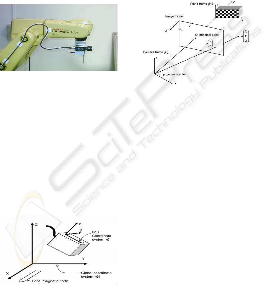
Our hybrid system is composed of an inertial sensor
and a CCD camera rigidly mounted onto a robot as
illustrated in Figure 1.
Figure 1: Hybrid system mounted onto the robot.
2.1 Inertial Sensor
The inertial sensor (MT9-B from Xsens) measures ac-
celerations, rate of turn and earth magnetic field. All
these data are in the right handed cartesian coordinate
system, {I}, as defined in Figure 2. This coordinate
system is the body-fixed to the Inertial Measurement
Unit (IMU) and it is substantially aligned to the exter-
nal housing of the IMU. The IMU software computes
the rotation of the IMU frame, {I}, with respect to
a global coordinate system, {G}, defined as a right
handed cartesian coordinate system (Figure 2) with
• X positive when pointing to the local magnetic
north.
• Y according to right handed coordinates (West).
• Z positive when pointing up.
Figure 2: IMU related frames.
2.2 Camera Model
Our vision sensor is a CCD camera (IS-800 from i2S
with 8mm focal length). Figure 3 illustrates the dif-
ferent frames used for the camera calibration. The
calibration procedure simulates the camera by a the-
oretical model which describes the transformation of
the scene (3D objects) toward the image.
Figure 3: Coordinate systems used in camera calibration.
The camera calibration determines the geometrical
model of an object and the corresponding image for-
mation system which is described by the following
equation
su
sv
s
!
= A [R T ]
X
Y
Z
1
(1)
where s is an arbitrary scale factor, (R, T ) called the
extrinsic parameters, is the rotation and translation
which relate the world coordinate system, {W }, to
the camera coordinate system, {C}, and A called the
camera intrinsic matrix given by
A =
α
u
0 u
0
0 α
v
v
0
0 0 1
!
(2)
with (u
0
, v
0
) the coordinates of the principal point
and α
u
and α
v
the scale factors according to u and
v image axes.
3 CALIBRATION PROCEDURE
We have rigidly mounted our hybrid tracker onto a
6DOF robot (LR Mate 200i from FANUC Robotics)
in order to exploit the accuracy of the robot position-
ing in a calibration process. The coordinate frames
used in the calibration procedure are illustrated in
VISION-INERTIAL SYSTEM CALIBRATION FOR TRACKING IN AUGMENTED REALITY
157
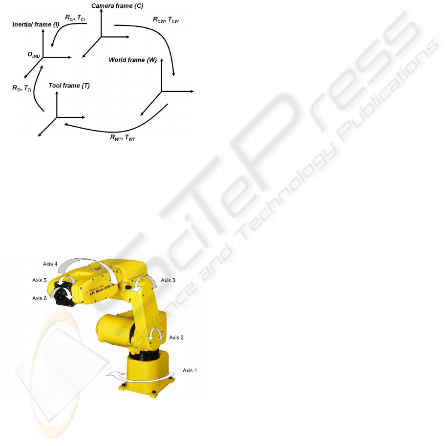
Figure 4. The transformation between two frames is
represented by the rotation matrix and the translation
vector. (R
CI
, T
CI
) is the transformation of the IMU
frame with respect to the camera frame, (R
IT
, T
IT
)
is the transformation of the tool frame with respect to
the IMU frame, (R
W T
, T
W T
) is the transformation of
the robot tool frame with respect to the world frame
and (R
CW
, T
CW
) is the transformation of the world
frame with respect to the camera frame.
Figure 4: Coordinate frames related to the hybrid system.
The used robot is a manipulator arm (Figure 5), it
is composed of six rotation axes. The robot is com-
pletely articulated with its six axes, its tool (axis 6) is
the reference for motion and all settings applications.
Figure 5: Robot and rotation axes.
The robot provides the coordinates of its tool frame
with respect to a user reference frame. Consequently,
to determine the position of a new tool frame in a new
user frame, it is necessary to make a learning of both
frames: tool and user.
3.1 Robot Frames
By default, the user frame is related to the basis of
the robot (axis 1). The robot data are expressed in the
tool frame with respect to the robot user frame. Nev-
ertheless, the transformation between the robot user
frame and the world frame of the camera is unknown.
For this purpose, we define a new user frame, {U}, to
have the same orientation as the camera world frame,
{W }. We learn also a new tool frame, {T }, so that
{T } and {I} are coincident. The aim of these frames
definitions is to derive directly the pose of the IMU
frame from the robot computed coordinates.
3.1.1 Definition of the Tool Frame
This frame is related to the last axis of the robot. As
we want to align the tool frame and the IMU frame,
we define the axes of {T } according to {I} axes using
six points method for learning.
3.1.2 Definition of the User Frame
The three points method is used to learn the user
frame. It consists on moving the tool to the beginning
and according to two other points on the X and Y
axes of the user frame which is in this case the world
camera frame.
3.2 IMU Calibration
3.2.1 IMU Orientation
Method 1 We can determine the IMU orientation
with respect to the global frame which is by defini-
tion related to the earth magnetic field. We can also
compute the IMU orientation in an earth fixed coor-
dinate frame that is different from the global coordi-
nate frame. In this work, we defined a new global
coordinate frame, {G}, the IMU has to be orientated
in such a way that the sensor axes all point onto ex-
actly the same direction as the axes of the global co-
ordinates frame (Figure 6). Afterwards, the orienta-
tion output will be with respect to the newly defined
global axes. The IMU is used to record orientation
of 3D object in real time. However, when the IMU is
mounted onto an object which contains ferromagnetic
materials (for example a camera) the measured mag-
netic field is distorted and this will cause errors on the
orientation measurement.
We can also obtain the position of the IMU by in-
tegrating the acceleration data. It’s theoretically pos-
sible to double integrate accelerometer data, after co-
ordinate transformations and subtraction of the accel-
eration due to gravity, we obtain 3D position data.
To implement this, some practical issues will be en-
countered:
ICINCO 2005 - ROBOTICS AND AUTOMATION
158

Figure 6: New global frame of the IMU.
• We need a ”starting point”, a reference 3D position,
from which we can start to integrate the 3D accel-
eration data.
• Noise on the acceleration data and small offset er-
rors and/or incorrectly subtracted acceleration due
to gravity, will be integrated and over time will
cause huge (drift) errors in the position estimate if
used longer than a few seconds without any exter-
nal update of true position.
The conclusion is that the orientation and also the
position determined by this method depends very
much on the type of motion and the environment in
which we are operating. For the position estimation
typically, short duration motions, preferably cyclical,
with known reference positions will work well. We
must also take into account the magnetic perturba-
tions, actually, the orientation measured by the IMU
is affected by the disturbances caused by the ferro-
magnetic objects present in the environment. These
constraints and problems obliged us to choose an-
other method more appropriated for our application
which needs accurate orientation and position mea-
surements.
Method 2 As we already evoked, the robot gives
the position of the tool located at the end of its last
axis with respect to a defined user frame. Knowing
the positioning of the IMU with respect to the robot
tool, we deduce the transformation between the IMU
related frame, {I}, and the user frame, {U}, where
{U} represents the camera world frame.
The IMU rotation with respect to the camera frame
is
R
CI
= R
CW
.R
W T
.R
T I
(3)
where R
CI
and R
CW
are respectively the rotation of
the IMU frame and the world frame with respect to the
camera frame, R
W T
is the rotation of the tool frame
with respect to the world frame and R
T I
is the rota-
tion of the IMU frame with respect to the tool frame.
3.2.2 IMU Translation
For this part, we use also the data provided by the ro-
bot, which are the coordinates of its tool frame, {T },
with respect to its user frame, {U}. A simple read-
ing on the robot control tool, allows to know the three
translation components of the tool with respect to the
user frame.
Nevertheless, we need to determine the translation
of the IMU frame, {I}, with respect to the camera
frame, {C}. Then, it is important to know exactly the
position of the IMU frame with respect to the robot
tool frame, {T }.
Indeed, the coordinates of the IMU frame origin,
O
IM U
, according to the tool frame, represent the
translation of the IMU frame with respect to the tool
frame, we denote it T
T I
. This translation is computed
from reported measurements and manufacturer data.
T
T I
is known, we compute T
W I
, the translation of the
IMU frame with respect to the world frame. We apply
the following formula of coordinate transformation to
determine T
W I
T
W I
= R
W T
· T
T I
+ T
W T
(4)
Finally, the translation to T
CI
is given by
T
CI
= R
CW
· T
W I
+ T
CW
(5)
3.3 Camera Calibration
In this work, we have used a calibration method which
is based on Zhang technique (Zhang, 1998). The cam-
era observes a planar pattern from a few (at least two)
different orientations. We can move either the camera
or the planar pattern, the motion does not need to be
known. The camera intrinsic and extrinsic parameters
are solved using an analytical solution, followed by a
nonlinear optimization technique based on the maxi-
mum likelihood criterion (Zhang, 1998). Radial and
tangential lens distortions are also modeled and very
good results have been obtained compared with clas-
sical techniques which use two or more orthogonal
planes.
From (1) the rotation matrix and the translation
vector are computed during the determination of
the camera parameters in the calibration procedure.
This transformation expresses the orientation and the
translation of the camera frame, {C}, with respect to
the camera world frame, {W }.
4 EXPERIMENTS
4.1 Experimental Setup
The hybrid tracker calibration procedure described in
the previous section was experimented. We have de-
VISION-INERTIAL SYSTEM CALIBRATION FOR TRACKING IN AUGMENTED REALITY
159
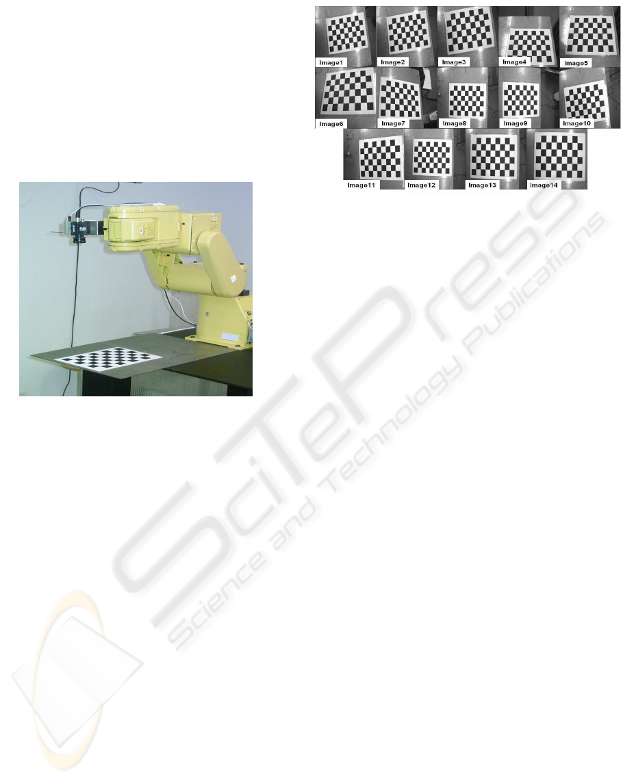
termined the rigid transformation between the camera
and the IMU frame using the calibration bench illus-
trated in Figure 7. The hybrid system is mounted onto
the robot. First, we fix a metal point to the IMU hous-
ing (Figure 1 and Figure 7). The end of this point
defines our tool frame which represents the motion
reference and used for all frame learning operations.
We set a test card opposite to the system to calibrate
the camera and to learn the user frame of the robot.
Then, we report the robot tool coordinates for each
recorded position.
Figure 7: Calibration bench.
4.2 Orientation between IMU Frame
and Camera Frame
Since the first method which uses the orientation com-
puted by the IMU software does not give good exper-
imental results, we use the robot data which are the
orientation and the position of the tool frame with re-
spect to the user frame.
As we already said, for the kinematics simplicity,
we define a tool frame, {T }, which has the same ori-
entation as the IMU frame, {I}.
Hence, the rotation between these two frames is an
identity matrix
R
T I
=
1 0 0
0 1 0
0 0 1
!
(6)
The user frame, {U }, is aligned to the camera
world frame, {W }. Then, the IMU orientation is di-
rectly given by the orientation of {T } with respect to
{W }.
The camera orientation is computed by calibration.
Several images taken from different viewpoints were
used for this procedure (Figure 8).
We used a single camera with 8mm lenses and
640×480 8-bit grayscale images. For the experiment,
Figure 8: Camera images used for the calibration.
we have tried various numbers of images. The used
formulation needs at least 2 images in different orien-
tations for the pose estimation. On the other hand, we
found that using more than 14 images did not increase
the accuracy any more. In the experiment, there are
40 corner points in each image. After calibration, the
obtained results for the camera internal parameters
are: the scale factors (α
u
, α
v
) = (989, 986) pixel,
the image center (u
0
, v
0
) = (380, 283) pixel, the ra-
dial distortions (k
1
, k
2
) = (−0.2395, 0.3938) and the
tangential distortions (t
1
, t
2
) = (−0.0004, −0.0018).
The extrinsic parameters are represented by the rota-
tion matrix and the translation vector of patterns po-
sition in the image.
The RMS (Root Mean Square) error between the
original and the reconstituted image points is equal to
2.6525 pixels
2
. Of course we introduced the radial
and tangential distortions into the perspective projec-
tion matrix to correct geometric errors of the camera.
The rotation of the IMU frame, {I}, with respect
to the camera frame, {C}, is determined by
R
CI
= R
CW
.R
W I
(7)
The rotation angles of the IMU with respect to the
camera are finally computed from the rotation matrix
R
CI
.
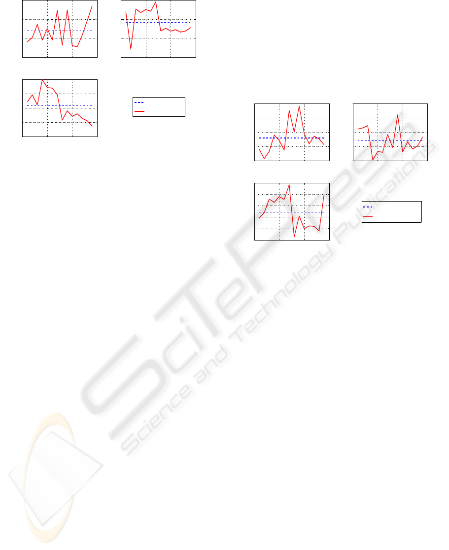
We used 14 positions of our hybrid sensors system
and we notice on the whole that the obtained rotation
angles are practically the same. However, to evaluate
efficiently the performance of this method, the rota-
tion measurement errors are computed (Figure 9).
Evaluation of the Rotation Errors The mean
value of each angle is computed and the static error
corresponding to each angle measurements is deter-
mined.
The mean rotation errors (MRE) of the angles are
MRE
ψ
= 0.32
◦
MRE
θ
= 0.30
◦
MRE
φ
= 0.18
◦
(8)
ICINCO 2005 - ROBOTICS AND AUTOMATION
160
0 5 10 15
89
89.5
90
90.5
Experiments
Variation of psi angle (°)
0 5 10 15
−1.5
−1
−0.5
0
Experiments
Variation of theta angle (°)
0 5 10 15
88.2
88.4
88.6
88.8
89
Experiments
Variation of phi angle (°)
Mean value of angles
Angle measures
Figure 9: Variation of the IMU rotation angles.
Finally, the rotation angles of the IMU frame with
respect to the camera frame are given by the following
mean values
ψ = 89.69
◦
θ = -0.59
◦
φ = 88.63
◦
(9)
4.3 Translation between IMU Frame
and Camera Frame
To compute the translation of the IMU origin, O
IM U
,
in the camera frame, it is necessary to know the po-
sition of O
IM U
in the world frame, T
W I
, and then
project into the camera frame. First, we determine
the translation of the IMU frame with respect to the
tool frame which is computed using the projection of
O
IM U
coordinates into the robot tool frame (see (4)
and (5)). The coordinates of O
IM U
with respect to
the tool frame are
O
IM U
(mm) =
-6.0
7.8
75.0
!
{T }
(10)
For this experiment, we use the same positions and
orientations of the robot which were used to compute
the IMU rotation in the camera frame.
We replace the values of T
W T
and T
CW
in (4) and
(5) where T
T I
is O
IM U
given in (10).
Evaluation of the Translation Errors We compute
the mean value of each component of the T
CI
coor-
dinates for all robot positions used for this calibra-
tion (Figure 10). The mean translation errors (MT E)
components are
MT E
X
= 1.5 mm
MT E
Y
= 1.5 mm
MT E
Z
= 1.2 mm
(11)
Finally, the translation of the IMU frame with re-
spect to the camera frame is given by the following
vector which expresses the coordinates of the IMU
with respect to the camera frame
T
CI
(mm) =
7.2
40.8
-41.6
!
(12)
0 5 10 15
4
6
8
10
12
Experiments
X position variation (mm)
0 5 10 15
38
40
42
44
46
Experiments
Y position variation (mm)
0 5 10 15
−44
−43
−42
−41
−40
−39
Experiments
Z position variation (mm)
Mean value of coordinates
Coordinate measures
Figure 10: Variation of the IMU translation coordinates.
5 CONCLUSIONS
In this work, we presented a new approach to calibrate
a hybrid tracking device for an augmented reality sys-
tem. The system consists on a camera and an inertial
measurement unit rigidly attached and mounted onto
a robot tool axis. This robot allows the displacement
of its tool in a workspace and computes the position
and the orientation of the tool frame in a defined ref-
erence frame. The calibration of the camera and the
coordinates provided by the robot determine the trans-
formation between the inertial measurement unit and
the camera with high accuracy.
The obtained calibration accuracy is sufficient for
the tracking application for which this hybrid system
was concerned. The evaluation of the numerical re-
sults showed the validity and the effectiveness of the
proposed approach.
Our future work is to test prediction filters with real
data provided by this hybrid system. We will integrate
the robot information data to correct and evaluate the
tracking methods before implementing prediction al-
gorithms on a portable AR system.
VISION-INERTIAL SYSTEM CALIBRATION FOR TRACKING IN AUGMENTED REALITY
161

REFERENCES
Azuma, R. (1997). A survey of augmented reality. In Pres-
ence:Teleoperators and Virtual Environments, Vol.6,
No.4, pp. 355-385.
Azuma, R. and Bishop, G. (1995). Improving static and
dynamic registration in an optical see-through hmd.
In Proceedings of SIGGRAPH 95.
Bajura, M. and Neumann, U. (1995). Dynamic registra-
tion correction in augmented reality systems. In Pro-
ceedings of IEEE Virtual Reality Annual International
Symposium, pp. 189-196.
Chai, L., Hoff, W., and Vincent, T. (2002). Three-
dimensional motion and structure estimation using in-
ertial sensors and computer vision for augmented re-
ality. In Presence: Teleoperators and Virtual Environ-
ments, Vol.11, pp. 474-492.
Foxlin, E. (2003). Vis-tracker: A wearable vision-inertial
self-tracker. In Proceedings of the IEEE VR2003.
Jacobs, M., Livingston, M., and State, A. (1997). Manag-
ing latency in complex augmented reality systems. In
Proceedings of the 1997 Symposium on Interactive 3D
graphics.
You, S. and Neumann, U. (2001). Fusion of vision and gyro
tracking for robust augmented reality applications. In
Proceedings of IEEE VR2001, pp. 71-78.
You, S., Neumann, U., and Azuma, R. (1999). Hybrid iner-
tial and vision tracking for augmented reality registra-
tion. In Proceedings of IEEE VR’99, pp. 260-267.
Zhang, Z. (1998). A flexible new technique for camera cal-
ibration. In Technical Report MSR-TR-98-71.
ICINCO 2005 - ROBOTICS AND AUTOMATION
162
