
PATH FOLLOWING IN UNKNOWN ENVIRONMENT FOR A
CAR-LIKE MOBILE ROBOT
Niramon Ruangpayoongsak and Hubert Roth
Institute of Automatic Control Engineering, University of Siegen, Hoelderinstr. 3, D-57068 Siegen, Germany
Keywords: Path following, Mobile robot, Obstacle avoidance, Trajectory generation.
Abstract: The path following is the automatic control of the mobile robot along the specified path without human
interference. The proposed path following applies for the robot navigation in unknown environments, where
the robot has no preliminary information about obstacles. This paper presents an innovative idea for the path
following control that is to integrate the basic path following control with the obstacle avoidance and the
trajectory generation. The robot performs the basic path following control with obstacle detection using on
ultrasonic and infrared sensors. The obstacle avoidance is developed by wall following technique and the
fuzzy logic controller. The trajectory generation is to generate the fittest trajectory to the desired final
position and heading. These algorithms base on the car manoeuvring characteristics.
1 INTRODUCTION
The path following control for mobile robots is the
automatic control of robot along the specified path
without human interference. The path following
control in unknown environment requires intelligent
navigation and localization. That is the integration of
the basic path following control, the obstacle
avoidance, and the trajectory generation.
The basic path following control is the path
following control under the assumption that no
obstacle exists during the operation. The robot
moves along the specified path and stops at the
destination without obstacle detection. In unknown
environment, where the obstacle positions are not
priori known, the basic path following control
method with the obstacle avoidance.
The obstacle avoidance is to detect the obstacle
positions, to avoid collision into obstacles, and to
overcome obstacles into free space. For a small
mobile robot, the compact size and the light weight
sensors are suitable. Several sensors exploited on
mobile robots are discussed in (Nehmzow, 2003). As
a part of the path following control, the obstacle
avoidance algorithm decides the orientation of the
robot for the next move by considering not only the
obstacle position, but also the robot current position
and the desired final position.
When that robot is free from obstacles and is
no longer on the original path, the robot has to
approach to the desired final position. The trajectory
generation provides the fittest trajectory between the
current robot position and the desired final position
using on the car manoeuvring characteristics.
This paper is organized as follows. Section 2
describes the mobile robot, section 3 explains the
path following control with obstacle avoidance,
section 4 presents the experimental results and
section 5 is the conclusion.
2 MOBILE ROBOT
A series of mobile robots MERLIN has been
designed and developed (Kuhle et. al., 2004, Roth et.
al., 2003). For a broad spectrum of indoor and
outdoor tasks on basis of standardized functional
modules like sensors, actuators, wireless
communication are implemented. Sensors onboard
are
• a gyroscope for angular velocity
measurement
• hall sensors as odometer
• ultrasonic and infrared sensors for obstacle
detection
• bumpers for crash detection
• a 3D magnetic compass for absolute roll,
pitch and yaw angle
455
Ruangpayoongsak N. and Roth H. (2005).
PATH FOLLOWING IN UNKNOWN ENVIRONMENT FOR A CAR-LIKE MOBILE ROBOT.
In Proceedings of the Second International Conference on Informatics in Control, Automation and Robotics - Robotics and Automation, pages 455-458
DOI: 10.5220/0001180904550458
Copyright
c
SciTePress
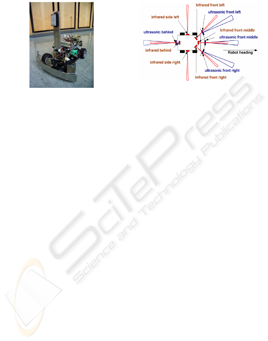
Figure 2: Ultrasonic and infrared sensor positions
Figure 1: MERLIN
As shown in Fig. 1, MERLIN is controlled by
80C167 CR 16 bit-processor. The microprocessor is
employed for interfacing sensor data acquisition.
MERLIN is controlled with the driving principle of
a car, steering the front wheels by a servomotor and
propelling the rear wheels by a dc motor.
3 PATH FOLLOWING WITH
OBSTACLE AVOIDANCE
The obstacle avoidance algorithm design bases on
the perception of robot. Due to light on weight and
compact in size, the four ultrasonic and six infrared
sensors are exploited and their positions are shown
in Fig. 2. The infrared sensor provides short distance
obstacle detection of up to 0.8 meter whereas the
ultrasonic sensors provide far distance detection of
up to 7.0 meter. For the sensors on the front and on
the back, the infrared sensors have higher priority
than the ultrasonic sensors regarding the fast
measurement updates. The ultrasonic sensors take
longer cycle time on waiting for the reflected signal.
Therefore, the infrared measured data replaces the
ultrasonic measured data, when the obstacle lies
within 0.8 meter from the robot.
3.1 Obstacle avoidance by wall
following technique
The designed wall following algorithm can be
categorized into two modes, the left hand side and
the right hand side wall following. The wall
following control is to steer the robot to stay far
from the wall or the obstacle border at a specified
distance. Due to small memory requirement for the
computation, the fuzzy logic controller (
Driankov et.
al., 1993
) is selected for steering control. The steering
fuzzy logic control is also combined with if-then
control for wall edges following. The if-then control
is the corporation between steering and propelling
control for the series of concatenated movements.
3.2 Trajectory generation
Based on the car manoeuvring, the examples of the
trajectories are shown in Fig. 3. As shown in Fig. 3a,
the trajectory consists of two unsymmetrical sub-
paths with different radius of the curvature of each
sub-path r
1
≠
r
2
.
Also, the final heading angle of
each sub-path is unequal
θ
1
≠
θ
2
. The distance to
destination dx and dy are the distance between the
current position and the destination in x and y
direction. Note that the robot heading is referred to
x-axis direction. The distances to the destination is
calculated by
dx = r
1
sin
θ
1
+ r
2
sin
θ
2,
(1)
dy = r
1
cos
θ
1
+ r
2
cos
θ
2,
(2)
Let
θ
1
=
θ
2
and r
1
=
r
2
. As a result, the sub-paths are
symmetry as shown in Fig. 3b. The distances to the
destination of the symmetrical sub-paths are
dx = 2r
1
sin
θ
1
,
(3)
dy = 2r
1
cos
θ
1
.
(4)
As shown in the figure, by fixing the radius r
1
and varying the angle as
θ
1
,
α
1
, and
β
1
, the final
destination 1, 2, and 3 are obtained. In the iterative
loop, the angle
θ
1
and radius r
1
are varied from 5 to
90 degrees and from 1 to 5 meters, respectively. The
minimum of the 1 meter radius is the shortest
curvature radius that the robot can perform. The 90
ICINCO 2005 - ROBOTICS AND AUTOMATION
456
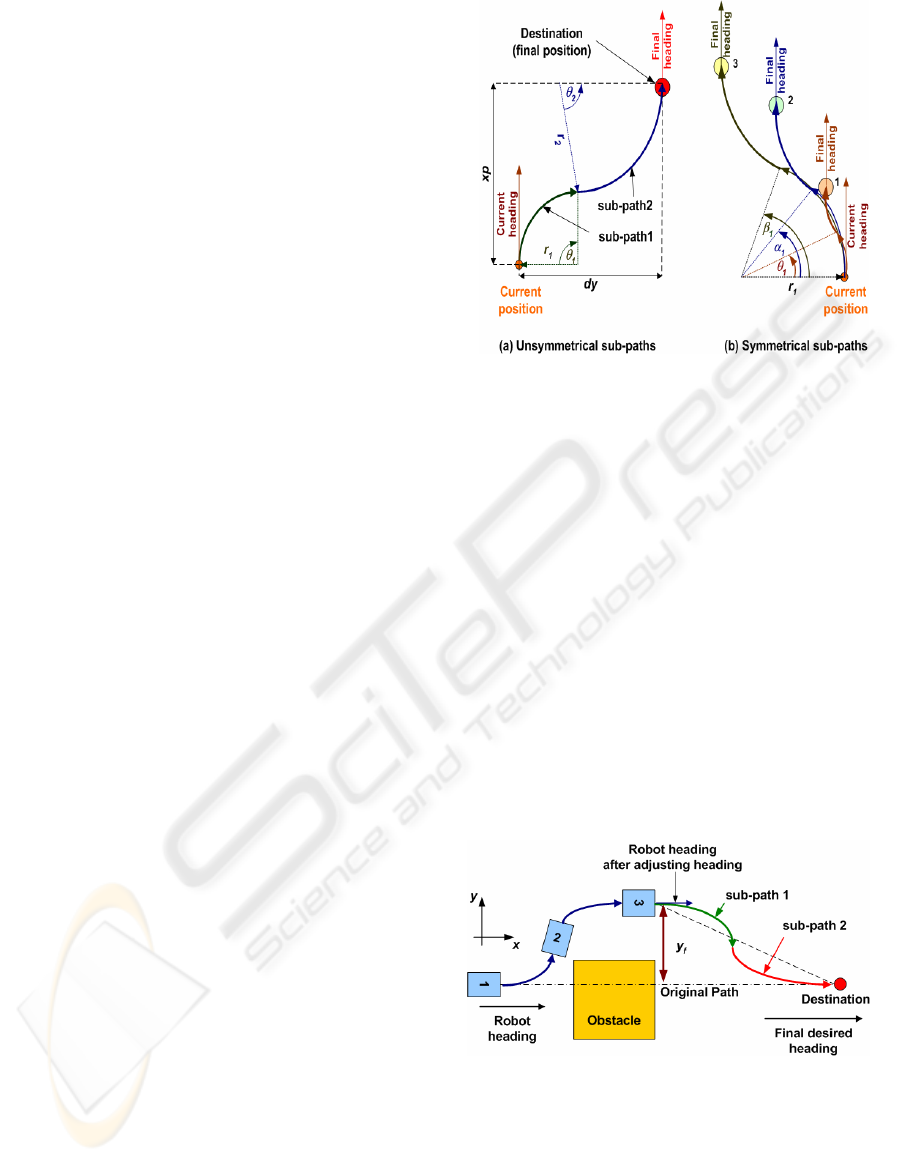
Figure 3: Trajectory generation
degrees is the maximum angle for each sub-path.
The brute force algorithm is applied for searching
the fittest trajectory by using
x
f
= x
final
– x
current
, (5)
y
f
= y
final
– y
current
, (6)
e
x
= x
f
– dx, (7)
e
y
= |y
f
| – dy, (8)
e
sum
= |e
x
|+ |e
y
|, (9)
where x
final
, y
final
, x
current
,
and y
current
are the final and
current coordinates, respectively. The fittest path is
the trajectory with the minimum error value e
sum
.
Note that for all generated candidate trajectories, the
current heading is also the final heading regarding
the symmetry of the two sub-paths as shown in Fig.
3b.
3.3 Basic path following control
The basic path following using the open loop
steering control is developed. During the operation,
the steering angle is fixed until the robot reaches the
destination. Two types of path are curve path and the
line path.
The examples of the curve paths are the sub-
paths in Fig. 3a. The path data are the final heading
θ
1
, the radius r
1
, and the movement direction,
forward or backward. The well calibrated gyroscope
provides the angular velocity measurement. The
integration of this measured signal is the robot
heading. The robot stops, where the robot current
heading equals the final heading. For a line path, the
command packet consists of the path length and the
movement direction. Hall sensors provide the driven
distance measurement. The robot stops, where the
driven distance equals the path length.
Figure 4: Path following strategy
3.4 Path following strategy
The integration of the obstacle avoidance, the
trajectory generation, and the basic path following
control is presented here.
As shown in Fig. 4, the original path command is
a dash line through the obstacle to the destination.
Initially, the robot receives a path command from
the user and records its current position and heading.
When the robot detects the obstacle, it stops in front
of obstacle at position 1. The robot chooses to
perform the left or the right hand side wall following
by comparing the measured distance from the front
left and the front right sensors. The wall following is
accomplished, when there is no obstacle in the front.
The robot is free from obstacle at position 2. The
robot stops and calculates the different between the
current heading and the desired final heading. Then
the robot adjusts its heading by turning into the final
heading. The robot heading equals the final heading
at position 3.
At this moment, the robot checks the distance to
the final position y
f
. If the distance y
f
is shorter than
0.2 m, the trajectory generation is neglected and the
robot moves straight on to the destination.
Otherwise, the robot sends a request for the
trajectory generation. At this stage, since the robot
heading is pointing to the desired final heading, the
trajectory generation by using (3 - 9) is performed
on the client PC and the generated trajectory consists
of two symmetrical sub-paths. After the robot
receives the generated sub-paths, the robot moves
along the sub-path 1 and sub-path 2 and finally
reaches the destination. At the destination, the robot
heading points to the desired final heading and the
PATH FOLLOWING IN UNKNOWN ENVIRONMENT FOR A CAR-LIKE MOBILE ROBOT
457
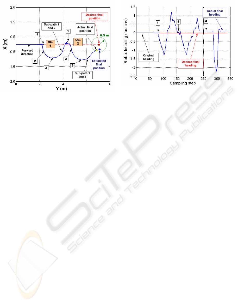
Fi
g
ure 6: Robot headin
g
Figure 5: Robot
p
osition
robot position is at the desired final position. If the
robot founds obstacles before it reaches the
destination, the process is repeated again from
position 1. The localization technique used is
presented in the paper: “Localization for a car-like
mobile robot using nonlinear dynamic model”.
4 EXPERIMENTAL RESULTS
The desired final position is at 7 meter in forward
direction as shown in Fig. 5. The solid line
represents the estimated robot position and the dash
line represents the original path. The position
numbers are pointed as described in the previous
section. The robot founds the 2
nd
obstacle at 4.3 m.
There, the process is repeated again from position 1.
The actual final position is the real position on the
ground and is close to the estimated final position
from localization. The actual final position lies
within the radius of 0.5 meter around the desired
final position. The robot heading during the
operation is shown in Fig. 6. The robot heading is
adjusted two times at position 3 and the actual final
heading is 0.13 radians.
5 CONCLUSIONS
The path following control for a car-like mobile
robot in unknown environment using the integration
of the basic path following control, the obstacle
avoidance and the trajectory generation is
implemented. The fuzzy controller with the if-then
control is applied for the wall following obstacle
avoidance using on four ultrasonic sensors and six
infrared sensors. The presented trajectory generation
produces two symmetrical sub-paths for approaching
the desired final position and heading. The
experimental results show that the robot performs
the designed path following process successfully and
the robot final position and heading are closed to the
desired final position and heading.
REFERENCES
Driankov, D., Hellendoorn, H., Reinfrank, M., An
Introduction to Fuzzy Control, Springer-Verlag, 1993.
Kuhle, J., Roth, H., Ruangpayoongsak, N., 2004.
MOBILE ROBOTS and airships in a multi-robot
team. The 1st IFAC Symposium on Telematics
Applications in Automation and Robotics, Helsinki
University of Technology, Finland, pp. 67-72.
Nehmzow, U., 2003. Mobile Robotics: A Practical
Introduction, 2
nd
Edition, Springer-Verlag, London.
Roth, H., Schwarte, R., Ruangpayoongsak, N., Kuhle, J.,
Albrecht, M., Grothof, M., Heß, H., 2003. 3D Vision
Based on PMD-Technology for Mobile Robots.
Aerosense - Technologies and Systems for Defense &
Security 2003, SPIE Conference, Orlando, Florida,
paper no. 5803-66.
ICINCO 2005 - ROBOTICS AND AUTOMATION
458
