
AN OPEN OBJECT ORIENTED PATH PLANNING SYSTEM
Eleonora Fantini, Monica Reggiani, Stefano Caselli
RIMLAB: Robotics and Intelligent Machines Laboratory
Dipartimento di Ingegneria dell’Informazione
Universit
`
a di Parma
Parco Area delle Scienze, 181A, Parma, Italy
Keywords:
Motion Planning, Software Architecture, Generic Programming.
Abstract:
The paper describes the ongoing development of a motion planning system whose aim is to ease the study
and development of new planning strategies as well as the benchmarking and comparison of existing ones.
The system is implemented using open technologies and exploiting advanced object-oriented programming
concepts. It efficiently integrates multiple planning strategies and collision detection algorithms and provides
support for diverse geometric formats.
1 INTRODUCTION
Research on motion planning has demonstrated its
maturity with the development of planners that have
been successfully employed in a number of areas,
such as robotics, biology, and graphic animation. Sev-
eral libraries are currently available either from the
open source community (Motion Planning Kit, Mo-
tion Strategy Library, OxSim, Motion Planning Ker-
nel) or as a commercial product (KINEO Computer
Aided Motion).
In spite of its progresses and maturity, motion plan-
ning has achieved limited success, so far, in terms
of deep penetration into industrial applications, and
chances of tool sharing and dissemination inside the
community are still minimal. One of the reasons can
be devised in the fact that the majority of the research
efforts in the field have been focused on the efficiency
of the available libraries, neglecting their portability
and integrability into control architectures or CAE
systems. Currently, motion planning tools adopt a
plethora of input formats, specific representations and
implementation choices. It is hard to compare the per-
formance of the existing motion planning techniques
and assess their suitability for the problem at hand.
Motion planners are usually demonstrated by solving
a limited set of specific examples, on different plat-
forms and using incompatible or proprietary problem
representations.
Moreover, as the components of a library are usu-
ally strongly tied, the reuse of other software solu-
tions is often a painstaking process and might even
require reimplementation from scratch. Finally, the
frequent release of tools providing functionalities that
can be effectively exploited in motion planning sys-
tems (e.g. collision detection libraries, graphical rep-
resentations) exacerbates the need for a systematic
use of mature approaches in the design of planning
systems.
These remarks suggest that openness, extensibility,
reusability and scalability are characteristics of para-
mount importance for a motion planning system.
Object-Oriented Programming (OOP) and related
features, such as inheritance and polymorphism, have
been successfully exploited in the development of
complex component-based software systems. The
benefits provided by OOP have been celebrated for
decades: OOP introduces reusability, flexibility, ex-
tensibility. One of the reasons that prevented its wide-
spread adoption in research areas with strong time
constraints is the almost unavoidable penalty in ex-
ecution time introduced by the abstraction levels of
object oriented design. Only recently, advanced tech-
niques based on the template construct have been pro-
posed to solve the performance problems of OOP lan-
guages (Veldhuizen, 1998; Alexandrescu, 2001). The
main goal of this work is to present how these tech-
niques can be exploited in the development of a mo-
tion planning system whose aim is to ease the study
and development of new planning strategies and the
benchmarking and comparison of the existing ones.
While steps in this direction where taken in (Gipson
17
Fantini E., Reggiani M. and Caselli S. (2005).
AN OPEN OBJECT ORIENTED PATH PLANNING SYSTEM.
In Proceedings of the Second International Conference on Informatics in Control, Automation and Robotics - Robotics and Automation, pages 17-24
DOI: 10.5220/0001177600170024
Copyright
c
SciTePress
et al., 2001) and (Cameron and Pitt-Francis, 2001),
the work described in this paper takes several steps
further in exploiting advanced OOP concepts along
with interoperable representation languages.
The paper is organized as follows. Section 2
presents the overall architecture of the system. Sec-
tion 3 details the way a planning context should be
described to the system. Section 4 and 5, respectively,
describe the implementation of a dynamic support for
different geometry input formats and a static support
for multiple collision detection packages. Section 6
presents the developed 3D viewer, that can be used as
an effective graphical interface for motion planning
applications. A final section summarizes the contri-
butions of the paper.
2 SYSTEM ARCHITECTURE
At the Robotics and Intelligent Machines Laboratory
of the University of Parma, we are developing a path
planning system exploiting advanced OOP concepts.
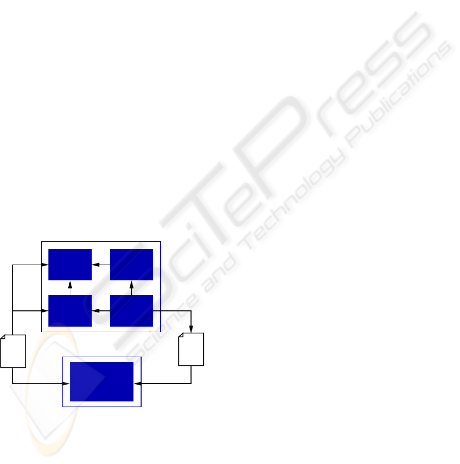
The major components of the tool are shown in fig-
ure 1. The system comprises a planning module writ-
ten in object oriented C++ and a 3D viewer written
in the Java language. A description of the environ-
ment and the robots involved in the planning problem
should be provided as input to both the modules. An
animation of the computed solution can be displayed
by the 3D viewer.
Geometry
Robot
Collision
Detection
Strategy
Planning
Strategy
Java Viewer
Application
Path
XML
File
Figure 1: Overall system architecture.
The planning module includes all the basic compo-
nents of a path planning tool: data structures repre-
senting robots and environment geometry, data struc-
tures representing robot kinematics, collision detec-
tion facilities and a planning strategy.
The planning strategy, the collision detection com-
ponent and the representation of geometry can be
recognized as dimensions of variability of a plan-
ning system. For these components it is possible
to make, either statically or dynamically, different
choices leading to substantially diverse performances.
A general tool that can be effectively used both in
the development of new planning strategies and in the
comparison and evaluation of existing ones, should
integrate different planning algorithms and allow the
user to choose the most suited for the application at
hand.
Moreover, as motion planning goal is to find a
collision-free path, it is intuitive that the overall ex-
ecution time is greatly affected by the quality of the
collision detection algorithm used by the planner. In
global planners, the execution time is dramatically in-
fluenced by the efficiency of collision detection. In
these planners, indeed, the whole connectivity of con-
figuration space (C-space) must be constructed, re-
quiring, for every possible robot configuration, colli-
sion checking against all the obstacles in the environ-
ment (Jimen
´
ez et al., 1998). In randomized planners
the C-space is incrementally explored, therefore only
a subset of robot configurations needs to be checked
for collision against obstacles. Nevertheless, in most
randomized path planners more than 90% of the over-
all execution time is spent for collision detection (Hsu
et al., 1998). Several robust collision detection pack-
ages are already available from research groups in
computational geometry. Partial comparisons of the
different algorithms are presented in (Mirtich, 1998;
Larsen et al., 1999) and (Reggiani et al., 2002), show-
ing that their relative performance also depends on the
problem characteristics. Therefore, a planner should
provide more than one collision detection routine, en-
abling an active role of the user to identify which li-
brary yields the best performance.
Finally, as a variety of CAD systems exist and as
the collision detection libraries adopt different geo-
metric object models, it is worth building a system
able to deal with different geometric descriptions.
This feature should both simplify to the user the prob-
lem modeling task and guarantee a full support for
collision detection libraries.
Stemming from the considerations above, the de-
sign approach followed in the development of the
planning system described in this paper, focused on
finding mechanisms able to effectively implement
variability, while minimizing code duplication and
programming efforts. The goal was to build an ex-
tensible system with points of flexibility that can be
customized by the user to suit a specific application,
without introducing loss in performance due to the
general structure. Details on the system components
are given in the subsequent sections.
ICINCO 2005 - ROBOTICS AND AUTOMATION
18

3 ROBOT AND ENVIRONMENT
DESCRIPTION
The description of the environments and the robots is
provided to the system through a set of XML (eXten-
sible Markup Language) files (http://www.w3.
org/XML). The idea to confine the description in
external files was suggested by the observation that
often the models of the involved robots are buried
into the code, preventing modification of the planning
problem without changes in the code itself. A gen-
eral tool should instead allow a rapid and inexpensive
reconfiguration of robots and a quick redesign of envi-
ronments to support a wide variety of planning prob-
lems.
A number of modeling languages are already avail-
able, but they are often too general and therefore they
do not provide high level abstractions for descrip-
tion of robotics-related mechanisms. To simplify the
modeling of a planning problem, a new XML-based
language specifically tailored to 3D robotic environ-
ments was developed. The choice of a markup lan-
guage was motivated by their common use in storage,
transmission and exchange of information as they al-
low the description of data and information contained
in text in a standardized format. Moreover, XML
has already proven convenient in describing various
types of structured data, as demonstrated by a grow-
ing number of XML-based languages in a wide range
of domains. XML documents are human-readable,
self-described, easy to maintain while guaranteeing
interoperability.
In this specific context, the XML Schema tech-
nology (http://www.w3.org/XML/Schema.
html) has been adopted to accurately define the
structure, contents and semantics of valid XML doc-
uments describing the robotic scenarios. In order to
simplify modeling of complex environments and to
encourage reuse in general, the definition of each el-
ement in the scenario is provided in a separate XML
file.
The semantics of workspace description allows in-
clusion of an arbitrary number of static objects in the
environment. For each object its geometry and posi-
tion are defined. Robots can be either mobile robots,
kinematic chains, a sequence of kinematic chains or
any system resulting from the composition of the pre-
vious ones. Mobile robots can be free-flying robots
or mobile robots on a plane. Kinematic chains are de-
scribed as sequences of links, and information about
shape and structure must be provided for each link.
In particular, the kinematic properties of the links are
expressed using the Denavit-Hartenberg parameters.
The choice of Denavit-Hartenberg notation (Harten-
berg and Denavit, 1955) is motivated by its wide use
that makes it a de facto standard for manipulator kine-
matics representation.
The geometry of the objects (static elements of the
workspace, links of kinematic chains, or any other
solid component of a robotic system) is described in a
uniform way. A solid object is defined as a set of geo-
metric shapes whose description is contained in sepa-
rate files: only the file names appear in the XML doc-
ument. As the geometric information is not directly
included in the XML file, the language is guaranteed
to be flexible and general: new file formats can be in-
cluded when needed, i.e. the extension of the system
to support additional geometric file formats does not
require changes in the XML document. The expres-
siveness of the developed XML language has been
empirically assessed by modeling a number of het-
erogeneous robots, including mobile platforms, ma-
nipulators, and parallel kinematic chains. A detailed
and comprehensive specification of the language can
be found in (Fantini and Reggiani, 2005).
4 GEOMETRY
In a planning context, the collision detection module
exploits the information about the geometry of the ob-
jects (obstacles and robots). The available collision
detection libraries can indeed be classified according
to the geometric object model they adopt (Lin and
Gottschalk, 1998), either polygonal (polygon soups,
convex objects, objects composed of convex parts) or
non-polygonal ( Constructive Solid Geometry (CSG),
implicit surfaces, parametric surfaces). Collision de-
tection libraries thus, usually require different input
formats. Moreover, the geometric representation can
influence the performance of the collision detection
algorithm. For example, algorithms working with
primitives are usually faster than those dealing with
polygonal soups. Therefore, a general system that
supports several collision detection algorithms should
also support multiple geometric formats.
As the type of input format is known only at run-
time when the files are read, the concepts of polymor-
phism and dynamic binding have been used to deal
with this dimension of variability of the system. In
the planning system, the design of the classes of the
geometry module follows the proxy pattern (Gamma
et al., 1995) shown in Figure 2.
Consider the case where the system should support
geometry models based on triangulation and CSG.
At compile time, the collision detection module must
deal with a surrogate, or proxy, of the class responsi-
ble for the handling of the input format. The proxy,
providing methods that can return to the caller ei-
ther the primitive based representation or the triangle
based one, hides the actual input format type.
AN OPEN OBJECT ORIENTED PATH PLANNING SYSTEM
19
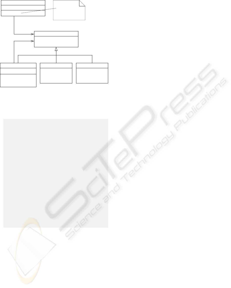
getTriangles
getVertices
getCSG
CSG
getTriangles
getVertices
getCSG
Triangulation
getTriangles
getVertices
getCSG
GeomRepresentation
imp: GeomRepresentationBase*
getTriangles
getVertices
getCSG
GeomRepresentationBase
CollisionDetection Tool
object: GeomRepresentation;
doSomething()
{
....
object.getTriangles()
....
}
Figure 2: Implementation of variability on file format using
the proxy pattern.
,
1 class GeomRepresentation
2 : public GeomRepresentationBase
3 {
4 private :
5 GeomRepresentationBase∗ impl ;
6 public :
7 GeomRepresentation ()
8 { / / depending on f i l e extension
9 impl = new Tri angul ation
10 / / or
11 impl = new CGS; }
12
13 void getTriangles ( l i s t <...>& t r i a n g les ) const ;
14 { impl−>getTriangles ; }
15
16 void getVertices ( l i s t <...>& vertexes ) const ;
17 { impl−>getVertices ; }
18
19 void getCSG( l i s t <...>& p r imitiv e s ) const ;
20 { impl−>getCSG; }
21 } ;
Listing 1: The proxy class for the application.
The GeomRepresentation class (Listing 1),
the proxy for the application, implements the
same interface (GeomRepresentationBase) of
the classes that provide the actual implementation
(Triangulationand CSG). The proxy instantiates
the real objects on demand, according to the formats
used by the input file and saves a reference to the ac-
tual implementation as an encapsulated object. All
subsequent requests are simply calls to virtual meth-
ods and are automatically routed to the appropriate
actual implementation. The module talks directly to
the proxy class and the common interface guarantees
that all the functions that the proxy needs are also im-
plemented in the Triangulationand CSGderived
classes.
This run time flexibility can potentially cause a
negative impact on performance due to the abstraction
levels introduced by object oriented design, but, being
limited to the initialization phase, it has, indeed, little
influence on the overall performance of the planner.
5 COLLISION DETECTION
As previously mentioned, the availability of multi-
ple collision detection algorithms is a distinct advan-
tage for a planning system. For the current version of
our tool, four collision detection packages have been
taken into consideration (Table 1). The selection was
based on their free availability for non-commercial
use, the ability to answer to the simplest query, i.e.
whether two models touch, and the capability to ac-
cept polygonal models.
The design approach followed in the implemen-
tation of the collision detection module aimed at
integrating the different packages without their
hard-wiring inside the motion planner code. An
earlier version of the tool integrated the chosen
packages according to the strategy pattern (Gamma
et al., 1995). With this pattern the algorithms are
implemented separately as subclasses of an abstract
strategy class. The planner forwards the responsi-
bility of collision detection to its strategy object.
While this implementation avoids the hard-wiring
of collision detection algorithms inside the planner
code, it causes inefficiency due to the abstraction
levels introduced to support the polymorphic be-
havior. This remark, together with the observation
that the choice of the collision detection algorithm
is immutable at runtime, suggested the use of
static polymorphism in the implementation of the
current version of the tool. Static polymorphism
is a more effective flavor of polymorphism based
on the use of templates. Templates were originally
conceived to support generic programming, as they
are functions or classes that are written for one
or more types not yet specified (Vandevoorde and
Josuttis, 2002). Each template parameter models one
degree of variability of the problem domain. This
parameter must be fixed at compile time allowing
the compiler to generate the proper code. This
static polymorphism guarantees type checking and
improves code optimization. Recently, recognition of
the ability of templates to perform code generation
gave birth to a new coding approach known as
generative programming. In particular, the degree
of variability of the motion planning system that
is related to the collision detection module, can be
effectively implemented using policy and policy
classes, the advanced generative programming tech-
ICINCO 2005 - ROBOTICS AND AUTOMATION
20

Table 1: Supported collision detection packages.
Library Developed by: Available at:
Rapid Gamma Research Group (Univ. of North Carolina at Chapel Hill) http://www.cs.unc.edu/
∼
geom/OBB/OBBT.html
SOLID Computer Graphic Group (Eindhoven Univ. of Technology) http://www.win.tue.nl/
∼
gino/solid/
V-Collide Gamma Research Group (Univ. of North Carolina at Chapel Hill) http://www.cs.unc.edu/
∼
geom/V
COLLIDE/
PQP Gamma Research Group (Univ. of North Carolina at Chapel Hill) http://www.cs.unc.edu/
∼
geom/SSV/
nique presented in details in (Alexandrescu, 2001).
,
1 class CollisionDetectionModellerPQP
2 {
3 public :
4 CollisionDetectionModellerPQP (
5 CollisionDetectionRepresentation const &);
6 bool c o l l i d e ( CollisionDetectionModellerPQP &);
7 void setRotoTrans ( matrix<double> const &);
8 double computeDistance (
9 CollisionDetectionModellerPQP &);
10 bool tolerance (
11 CollisionDetectionModellerPQP &);
12 private :
13 PQP model∗ surface ;
14 double rota t i o n Matrix [ 3 ] [ 3 ] ;
15 double tr a nsla t ionV ecto r [ 3 ] ;
16 protected :
17 ˜ CollisionDetectionModellerPQP ( ) ;
18 } ;
Listing 2: The policy class CollisionDetectionModeller-
PQP.
Briefly, policy-based class design consists in describ-
ing a behavior (a policy) that several policy classes
must be compliant to. The policy is a loosely defined
interface and the policy classes can expose extra
methods implementing additional functionalities.
In this specific context, a policy for the concept
of an object that can collide against another object
was defined. The policy prescribes the following
methods:
• a constructor with a GeomRepresentation ob-
ject parameter;
• a collide method that determines whether there
is a collision against another object;
• a method for the rototraslation of the object.
Listing 2 shows a policy class implementing the be-
havior just defined.The policy classes will also in-
clude the description of the object geometry as a
private member. This feature will hide to the user
the heterogeneity of the data structures the different
collision detection packages employ to store geom-
etry information. As previously stated, a policy is
not a traditional interface but it represents a config-
urable behavior for generic functions and types. This
means that the design of the concrete class imple-
menting the policy (policy class) is not strictly con-
strained to exclusively implement the set of meth-
ods defined in the policy. Therefore, it is possible
to have enriched policies, i.e. policy classes that ex-
pose methods implementing extra functionalities. As
an example, PQP provides two additional methods
(computeDistance and tolerance). Policy-
based class design does not oblige the developer of the
system to define a do-it-all interface (Alexandrescu,
2001).
,
1 / / L ibrar y code
2 template <class CollisionDetectionModeller>
3 class Obstacle
4 : public Collisio nD et ec ti on Mo deller
5 { . . . . } ;
6 template<class CollisionDetectionModeller>
7 class Link : public CollisionDetectionModeller
8 { . . . } ;
Listing 3: The library code.
This feature is particularly desirable in the collision
detection domain, where algorithms often offer vari-
ous additional queries together with the basic func-
tionality of collision detection. When the application
developer fails by calling a method which is not avail-
able in the chosen policy class, the error is detected
at compile time through the template instantiation
process, i.e. the compiler process of replacing tem-
plate parameters with concrete types. Listing 3 shows
how the defined policy can be exploited in a motion
planner. Policies are not intended for stand alone use:
they are usually inherited by, or contained within, an-
other class. In the planner, the policy is inherited by
the two classes that need collision detection facilities:
Obstacle and Link. Once a class inherits the Col-
lisionDetectionModeller policy, a collide method
that behaves according to the chosen policy class is
available among its methods. Of course, if the pol-
icy provides an enriched interface, the application can
also exploit the extra functionalities.
Listing 4 shows an example of application code.
Choosing a different collision detection package only
requires to define the template parameter (lines 2,4)
and recompile the code.
AN OPEN OBJECT ORIENTED PATH PLANNING SYSTEM
21
,
1 / / Appli ca tion code
2 typedef Obstacle<CollisionDetectionModellerRAPID>
3 ObstacleType ;
4 typedef Link<CollisionDetectionModellerRAPID>
5 LinkType ;
6
7 LinkType l i n k ;
8 ObstacleType obstacle ;
9 / / . . . s e ttin g the geometry of l i n k and obstacle
10 l i n k . co l l i d e ( obstacle ) ;
Listing 4: The application code.
5.1 Experimental Results
In order to evaluate the performance of the policy-
based implementation of the collision detection mod-
ule and to prove that no overhead is introduced by the
exploitation of this static polymorphism technique,
a series of experiments were carried out. This sec-
tion presents the details of chosen testbeds, the ex-
perimental methodology adopted, and the obtained
results. Two programs have been implemented for
each package. The first one (native implementation)
builds a collision checking routine as suggested by the
sample programs included with the packages. The
second program, instead, implements the collision
checking routine exploiting policy classes provided
by the collision detection module of the motion plan-
ner, as shown in the previous listing. All reported re-
sults have been obtained on a Pentium 4 1500MHz
PC with 512MB main memory. The code has been
compiled with gcc version 3.3.3 with the -O2 opti-
mization switch. In the first experiment, the two pro-
grams are required to evaluate collisions between one
of the link of a Puma 560 manipulator robot and a
grid-shaped workspace (Figure 3). To factor out the
effects of other path planner features, the analysis has
been limited to a single link. The grid workspace is
a convex object made of a composition of 8900 trian-
gles while the puma link is composed of 44 triangles.
A set of 500,000 configurations was randomly gen-
erated and tested with both programs. All the execu-
tions reported the same number of colliding config-
urations (132,745), 26% of the overall set. Table 2
reports, for each implementation, the total time for
collision checking and the average time required to
check a single configuration.
Due to a variability of less than 0.5 sec. on suc-
cessive executions, the reported results are an aver-
age on five experiments run on the same 500,000 con-
figuration set. The results show that there is no sig-
nificant difference in performance between the two
implementations. With the second testbed the dif-
ficulty of the problem was increased by substitut-
ing the Puma link with a CAD model composed of
69,451 triangles (Figure 3). The model represents
Figure 3: First testbed: a Puma560 link moving in a grid-
shaped workspace. Second testbed: a bunny model in a grid
shaped workspace.
Table 2: Average total collision checking time and average
time required to check a single configuration for the Puma
link problem.
Package native implementation policy implementation
Total 1 conf. Total 1 conf.
Time (s) (µs) Time (s) (µs)
RAPID 44.68 89.36 44.26 88.52
PQP 44.77 89.55 45.38 90.7
VCollide 45.59 91.19 45.47 90.9
SOLID 50.89 101.7 50.34 100.6
a bunny and is available from the Large Geomet-
ric Models Archive (http://www.cc.gatech.
edu/projects/large models). The same ex-
perimental methodology of the first test was adopted.
The programs returned a number of 263,874 colliding
configurations out of 500,000.
The total execution time (Table 3) for the collision
checking significantly increased due to the complex-
ity of the problem and the increase in the number
of colliding configurations (263,874 out of 500,000).
Despite the increased difficulty of the problem, no
substantial performance difference between the two
implementations could be revealed. Hence our path
planning system uses static polymorphism to attain in
a high level manner the benefits of multiple collision
detection packages without performance penalties.
Table 3: Average total collision checking time and average
time required to check a single configuration for the bunny
problem.
Package native implementation policy implementation
Total 1 conf. Total 1 conf.
Time (s) (µs) Time (s) (µs)
RAPID 87.71 175.42 87.8 175.6
PQP 88.62 177.25 89.03 178.06
VCollide 89.47 178.95 89.23 178.47
SOLID 83.55 167.11 83.76 167.53
ICINCO 2005 - ROBOTICS AND AUTOMATION
22
6 A JAVA3D-BASED VIEWER
The path planning system includes a 3D tool that
can be conveniently used as a graphical interface for
motion planning applications, as its aim is to sim-
plify the creation of virtual environments and robots.
The system is implemented using open technologies
(Java, XML) to provide full portability and interop-
erability on several computer platforms and through
the Internet. For the rendering of three-dimensional
graphics, the Java3D API (http://java.sun.
com/products/java-media/3D/) has been
exploited. This API is a collection of Java classes pro-
viding a high-level object-oriented interface for the
rendering of three-dimensional graphics programs.
Java3D properties make it well suited for the simu-
lation of virtual robots, as the language provides fa-
cilities to represent geometry, event handling for the
implementation of virtual sensors, and the possibility
to dynamically change the scene graph to emulate ro-
bot motion (Smith et al., 1999).
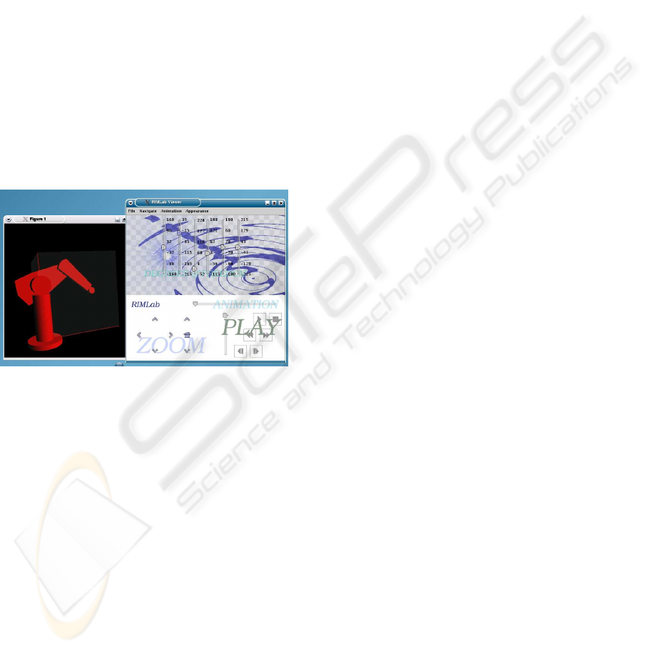
Figure 4: A screenshot of the Java3D tool.
The tool receives as input a set of XML files de-
scribing the robots and the environment to be dis-
played. The structure, contents and semantic of valid
XML documents are defined by the set of XML
Schemas describing the markup language presented
in section 3. The XML files are processed by a parser
realized exploiting the SAX API (http://www.
saxproject.org). Parsed information is used to
load the geometric description of the objects to be
displayed and to set up the scene graph that models
the robotic scenario. The Java3D Loader interface
has been used, as it provides a straightforward way to
deal with the different existing 3D file formats. Cur-
rent implementation of the tool supports triangulated
(gts, off, and vrml) and constructive solid geometry
formats, but it can be easily extended as a growing
number of loaders are made freely available on the
Web. Thanks to the use of XML, as it happens for
the motion planning application, the virtual scenario
description is fully decoupled from the tool internal
representation and data structures, and the user is not
required to deal directly with, nor to be aware of, the
3D representation of the scene.
Figure 4 is a screenshot of the tool: the graphical
interface on the right provides interaction commands
through a set of menus, buttons and sliders. Cur-
rent implementation of the tool supports navigation
functionalities such as change of viewpoint, zoom-
ing into/out of the scene, navigation into and rota-
tion of the scene using the mouse. Once the robot
model is loaded, users can change interactively the
robot configuration by modifying the values of its de-
grees of freedom either specifying a value in a text
box or using the sliders. Therefore, once a kinemat-
ically and geometrically correct model of a robotic
system is made available, the tool allows the inves-
tigation of several system arrangements and the as-
sessment of the resulting workspace and reachability
characteristics. In the motion planning context, the
3D tool provides a straightforward way to assess the
quality of planning solutions obtained for a wide vari-
ety of problems and to compare solutions of the same
problem computed by different planning strategies,
eventually exploiting different collision detection al-
gorithms. The same set of XML files used to describe
the planning problem to the motion planner can be
given as input to the viewer. Once the 3D scene is
loaded, an additional file containing the sequence of
configurations computed by the planner can be loaded
and an animation of the robot motion can be displayed
and therefore evaluated.
7 CONCLUSIONS AND FUTURE
WORK
In this paper we have described a motion planning
system that exploits advanced object-oriented pro-
gramming concepts and technologies that provide in-
teroperability. Thanks to this design approach the sys-
tem allows the efficient integration of multiple plan-
ning strategies and collision detection algorithms and
provides support for diverse geometric formats. Sup-
port for planning strategies is currently limited to
potential field planners (Caselli and Reggiani, 2000;
Caselli et al., 2002). Future work includes the im-
plementation of probabilistic roadmap techniques and
the exploitation of the planning tool in the context of
service robotics.
The system is open source and is freely available
for download (http://rimlab.ce.unipr.it)
upon request to the authors.
AN OPEN OBJECT ORIENTED PATH PLANNING SYSTEM
23

ACKNOWLEDGMENT
This research is partially supported by MIUR (Ital-
ian Ministry of Education, University and Research)
under project RoboCare (A Multi-Agent System with
Intelligent Fixed and Mobile Robotic Components).
The authors would also like to thank partecipants to
the meeting on motion planning benchmarks held in
Amsterdam in 2004 for the constructive discussion.
REFERENCES
Alexandrescu, A. (2001). Modern C++ design: generic
programming and design patterns applied. Addison-
Wesley Longman Publishing Co., Inc.
Cameron, S. and Pitt-Francis, J. (2001). Using OxSim for
Path Planning. Journal of Intelligent Robotic Systems,
8(18):421–431.
Caselli, S. and Reggiani, M. (2000). Erpp: An experience-
based randomized path planner. In IEEE Intern. Conf.
on Robotics and Automation, ICRA’00.
Caselli, S., Reggiani, M., and Sbravati, R. (2002). Par-
allel path planning with multiple evasion strategies.
In IEEE Intern. Conf. on Robotics and Automation,
ICRA’02.
Fantini, E. and Reggiani, M. (2005). A Practical Intro-
duction to the Motion Planning Markup Language
(MPML). Technical report, Robotics and Intelligent
Machines Laboratory (RIMLAB), Universit
`
a degli
Studi di Parma.
Gamma, E., Helm, R., Johnson, R., and Vlissides, J. (1995).
Design patterns: elements of reusable object-oriented
software. Addison-Wesley Longman Publishing Co.,
Inc.
Gipson, I., Gupta, K., and Greenspan, M. (2001). MPK: An
Open Extensible Motion Planning Kernel. Journal of
Intelligent Robotic Systems, 8(18):433–443.
Hartenberg, R. S. and Denavit, J. (1955). A kinematic nota-
tion for lower pair mechanisms based on matrices. J.
Applied Mechanics, 77:215–221.
Hsu, D., Kavraki, L. E., Latombe, J.-C., Motwani, R., and
Sorkin, S. (1998). On finding narrow passages with
probabilistic roadmap planners. In Parallel and Dis-
tributed Processing IPPS/SPDP, Orlando, FL.
Jimen
´
ez, P., Thomas, F., and Torras, C. (1998). Collision
detection algorithms for motion planning. In Lau-
mond, J.-P., editor, Robot motion planning and con-
trol, number 229, chapter 6. Lecture Notes in Control
and Information Sciences.
KINEO Computer Aided Motion (n.d.). http://www.
kineocam.com/.
Larsen, E., Gottschalk, S., Lin, M., and Manocha, D.
(1999). Fast proximity queries with swept sphere
volumes. Technical Report TR99-018, Department
of Computer Science, University of North Carolina,
Chapel Hill.
Lin, M. and Gottschalk, S. (1998). Collision detection be-
tween geometric models: a survey. In IMA Conference
on Mathematics of Surfaces.
Mirtich, B. (1998). VClip: fast and robust polyhedral
collision detection. ACM Transaction on Graphics,
17(3):177–208.
Motion Planning Kit (n.d.). http://robotics.
stanford.edu/
∼
mitul/mpk/.
Motion Strategy Library (n.d.). http://msl.cs.
uiuc.edu/msl.
Reggiani, M., Mazzoli, M., and Caselli, S. (2002). An ex-
perimental evaluation of collision detection packages
for robot motion planning. In IEEE Intern. Conf. on
Intelligent Robots and Systems, IROS’02.
Smith, N., Egert, C., Cuddihy, E., and Walters, D. (1999).
Implementing virtual robots in java3d using a sub-
sumption architecture. In AACE World Conference on
the WWW and the Internet, pages 975–980, Honolulu,
HI, USA.
Vandevoorde, D. and Josuttis, N. M. (2002). C++ Tem-
plates. Addison-Wesley Longman Publishing Co.,
Inc.
Veldhuizen, T. L. (1998). Arrays in blitz++. In 2nd Interna-
tional Scientific Computing in Object-Oriented Paral-
lel Environments (ISCOPE’98).
ICINCO 2005 - ROBOTICS AND AUTOMATION
24
