
EMBEDDED ROBOTIC CONTROL TECHNOLOGIES AND ITS
APPLICATIONS IN AUTOMATED PROGRAMMERS
Ganwen Zeng, Kelly Hirsch
Data I/O Corporation,, 10525 Willows Road NE, Redmond, WA 98052, USA
Keywords: Device Programming, Robotics, Motion control, Fuzzy control, Firmware, Embedded Software, Hardware.
Abstract: The paper presents a synthesis of the problematic and actual solutions to the implementation of robotic
programmer control functionality using DSP controllers. Considerable technology shift occurred during the
recently decade in device programming industry. The advent of high performance DSP motion controllers
opens new possibilities for the development of high performance distributed intelligence device-
programming automation systems. The idea of implementing a unique, flexible robotic motion control
structure can significantly improve controllability of the robotic programming systems. High-level motion
command languages are used to setup and to control the robotic motors. A Fuzzy control algorithm has been
introduced to guarantee the motion control performance in an automated programmer.
1 INTRODUCTION
Automated programming systems available today
are able to fully automate device programming and
to fully integrate programming testing, device
handling, and labelling programmable devices. It
improves the productivity, quality and flexibility of
a semiconductor production process.
High performance motor motion control
precision and high level of integration is
continuously increasing, and the clear trend is
towards completely integrated intelligent
programming system. This paper describes an
embedded intelligent programming automation
system that uses a Motorola free scale 32-bit
architecture MPC8xx PowerPC embedded processor
as a host machine. The fuzzy control has been
designed for a robotic motion control subsystems
using the Motorola 32-bit architecture 68376 digital
signal processor (DSP), and the high speed robotic
motion digital control system has been realised.
The system hardware is implemented using the
MPC8xx PowerPC and Motorola 68376 DSP. The
control task of the system, except programming
devices, includes the following components:
(i) Robotic task space configuration
(ii) Robotic head home probing
(iii) Head dynamic motion control
(iv) Programming device picking control
(v) Programming device placing control
(vi) Device feeding tape control
(vii) Belt transportation motion control
A high level of integration of system firmware
and embedded software has been proposed on
different real-time operating systems (RTOS) for
modern programming automation. Control software
can be developed to utilize DSP pulse width
modulation (PWM) and quadrature decoding
capabilities of the 68376’s TPU (Timer Processor
Unit). Source Code can be also developed to make
use of the processor’s TouCAN (Controller Area
Network) and QADC (Queued Analog to Digital
Converter) modules. The embedded software is
realized in C++ language with Object Oriented
Programming techniques (OOP). Main advantages
of this choice are the easy software maintenance and
reutilization, as well as its uniformity in terms of
internal organisation compared with the system
hardware module architecture. A fuzzy control
algorithm is designed for precision motion control.
Timing information is presented which shows how
the robotic shaft torque functions could be
implemented. One use case of the designed
embedded robotic control technologies could be the
DATA I/O ProMaster 3000 automated programming
system (see Figure 1). The ProMaster 3000 has been
designed by DATA I/O for flexibility. Pick-and-
place heads can rotate devices, so programming and
labelling proceed without interruption regardless of
device orientation in the tubes. A high-density,
thermal printer quickly prints and applies device
279
Zeng G. and Hirsch K. (2005).
EMBEDDED ROBOTIC CONTROL TECHNOLOGIES AND ITS APPLICATIONS IN AUTOMATED PROGRAMMERS.
In Proceedings of the Second International Conference on Informatics in Control, Automation and Robotics, pages 279-283
Copyright
c
SciTePress
labels, available in a wide variety of materials and
sizes, in one swift and precise operation.
Figure 1: ProMaster 3s000 automation system
2 CONTROL SYSTEM
DESCRIPTION
The control system of a general robotic programmer
is composed of one host commander and two main
motion control subsystems DPCS (Device
Positioning Control System) and DIOC (Device
Input Output Control System). The DPCS is
composed by 5 control units of robotic task space
configuration, robotic head home probing, head
dynamic motion control, device picking control and
device placing control. The DIOC is composed by
two control units of device feeding tape control and
device transportation belt motion control.
Synchronous communications can rely on the bus
Ethernet and TCP/IP protocol. Asynchronous
Communications between the host commander and
the control subsystems can be based on the TouCAN
bus or Motorola 68376 Com Ports to guarantee the
space loop closure for the main axes of the robotic
control system.
In the multiple robotic axis configurations of the
programmer automation system, the design is to
consider more and more distributed intelligence
control structures. This means the use of single-axis
intelligent DSP motion controllers for both DPCS
and DIOC which can handle local robotic axis
control function independently from the host
MPC8xx PowerPC. In the ProMaster 3000 use case
applications where the robotic motion handler and
device transportation belt controller are equipped
with different motor control technologies, the use of
one single command language simplifies the
complexity of the integration of control elements in
the system. Based on these considerations, we are
going to discuss the implementation of the basic
digital motor fuzzy control functionality, including
real-time operating kernel, PWM generating units,
current and motor torque control, speed/position
control, and fuzzy control algorithm.
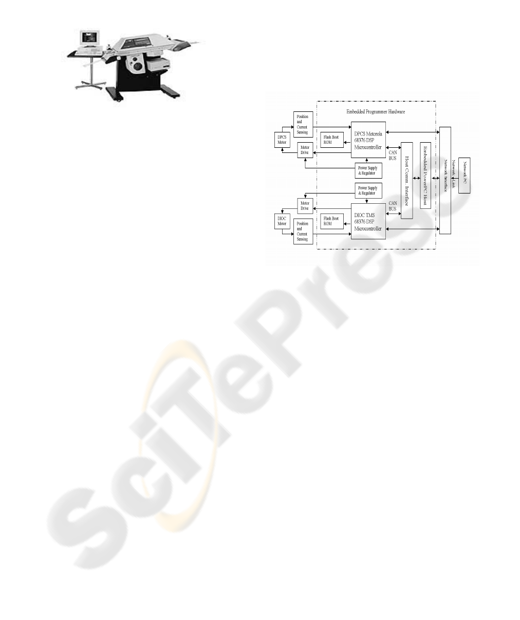
2.1 Motor DSP Motion Control
Hardware
The complete system consists of DC servo motors,
the motor control circuit, programmer processor, and
Network PC station as represented in Figure 2.
Figure 2: Block diagram of the control system of
automated programmer
The Motorola 68376 DSP is the shaft control
processor and carries out all the motion control and
torque current loop functions. The embedded motion
control software is stored on an external 16-bit Flash
bootrom and is automatically loaded into the DSP’s
internal program RAM on power-up. The DSP boot
firmware copies the program from the Flash memory
to the internal RAM, initialises all data variables
(look up tables, etc.), configures the DSP’s QADC
modules, and setups the PWM registers, and
performs self-diagnostic functions.
The second part of the embedded control
software contains the motion fuzzy control
algorithms, which are loaded at the end of the
initialisation phase. The shaft control algorithm can
be timed via the interrupt pin on the DSP.
2.2 Motion Control Structure
Figure 3 below illustrates a speed and torque control
scheme of DC motor for the motion control of the
device handler in a programmer robotic system with
an independent maximum current limit setting. The
quadrature decoding unit of the 69376’s TPU
samples the motor position and velocity, 68376’s
QADC analog-to-digital converter module samples
the motor currents. The feedback of motor current
ICINCO 2005 - INTELLIGENT CONTROL SYSTEMS AND OPTIMIZATION
280
and motor position/velocity sensing allows for
closed loop control of motor speeds. The outer
position and Proportional plus Integral (PI) velocity
control loop, based on the following robotic
dynamics, calculates the desired voltage control
error of the torque
d
V∆
, and the desired current of
the torque demand
d
i
, which is the reference input
for the current control loop.
)(),()(
θϑθθθτ
GVM ++=
…… (1)
Where
)(
θ
M
represents the mass matrix of the
distributed robotic joint,
),(
ϑθ
V
is the Coriolis
term of the robotic system,
)(
θ
G
is the gravity term
of the robotic system.
θ
is the angular position of
motor,
ϑ
is the angular velocity of the motor,
θ
is
the angular acceleration of the motor.
The desired voltage control error of the current
i
V∆
and the desired voltage control error of the
torque
q
V∆
are fed into the nonlinear fuzzy
controller. The nonlinear fuzzy control algorithm
implemented on the DSP calculates the desired
control voltage input
ctrl
V
for the motor. The DSP
scales and then generates PWM using the 68376’s
TPU from the
ctrl
V
, The velocity control is achieved
through varying the voltage across the terminals of a
motor by the Pulse Width Modulation that is the
continuous fast switching of motor voltage. By
varying the duty cycle from 0% to 100%, the
effective voltage across a motor can be established
from a set input of PMW duty cycle (
motor
V
). The
PWM duty cycle
motor
V
is fed into the motor drive
to drive the DC servo motor.
Figure 3: Motion control structure
Pulse Width Modulation (PWM) has both
bipolar and unipolar topologies, in the motion
control structure the bipolar PWM is used, which
switching voltage between a positive and a negative
set voltage (
motor
V
). In a bipolar a net positive
voltage across the motor can be achieved for a
positive duty cycle greater than 50%. This will drive
the motor forward, provided that generated torque is
greater than load torque. In the opposite case, if the
net voltage across the motor is negative, the motor
will be driven in reverse, provided that generated
torque is greater than load torque. If the duty cycle is
maintained at 50% the motor will remain stationary,
provided there is no load torque applied. PWM is
implemented in the motor drive circuit by the use of
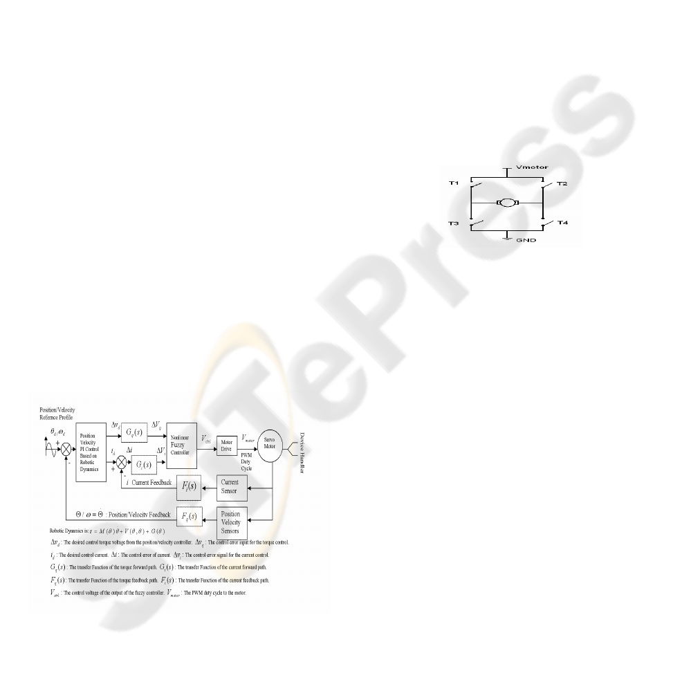
an H-bridge. A simplified H-bridge configuration is
shown in Figure 4. By varying switch states, the
motor can be placed in the following states:
(i) Driving forward (T1 on, T4 on)
(ii) Driving in reverse (T2 on, T3 on)
(iii) Braked to ground (T3 on, T4 on)
(iv) Braked to
motor
V
(T1 on, T2 on)
(v) Neutral/ Floating (all switches off)
Bipolar switching only makes use of states II and I.
Figure 4: A simplified H-bridge configuration
In order to sense small motor currents (less than
100mA), which can be difficult to be sensed in a
noisy environment such as brush noise due to the
make/break characteristic of brush commutation,
and torque ripple due to gearing effects; a custom
amplifier was built. That is properly scaled for the
expected motor currents, includes low-pass filtering
of sensed current before performing an A/D
conversion of the current feedback signal. The
second order active filter is used to reduce the
current feedback noise, which would otherwise be
amplified by the feedback circuit and cause
oscillations in motor speed.
2.3 Motion Control Hierarchy
The robotic control system presented in this paper
will implement, through the above specified
hardware and the corresponding embedded software
modules, the hierarchical robotic motion control
architecture shown in Figure 5. The are four low-
level modules, i.e., the H-Bridge, PWM Generator,
Nonlinear Fuzzy Control and Position/Velocity PI
Control blocks, will implement the basic motor
control functionality. The high-level modules, i.e.,
the feedback Signals Measurement, Reference
EMBEDDED ROBOTIC CONTROL TECHNOLOGIES AND ITS APPLICATIONS IN AUTOMATED
PROGRAMMERS
281
Generator, Motion Language Definer and
Communication Message Queue blocks, will
implement the motion control functionality.
All these modules are interconnected within a
hierarchical model, the output of one module being
the input of the subsequent low-level module. All
the modules are fit into the Motorola 68376 DSP
micro-controller that would play the role of a
“Motion Control Chip”.
Figure 5: Motion control hierarchy
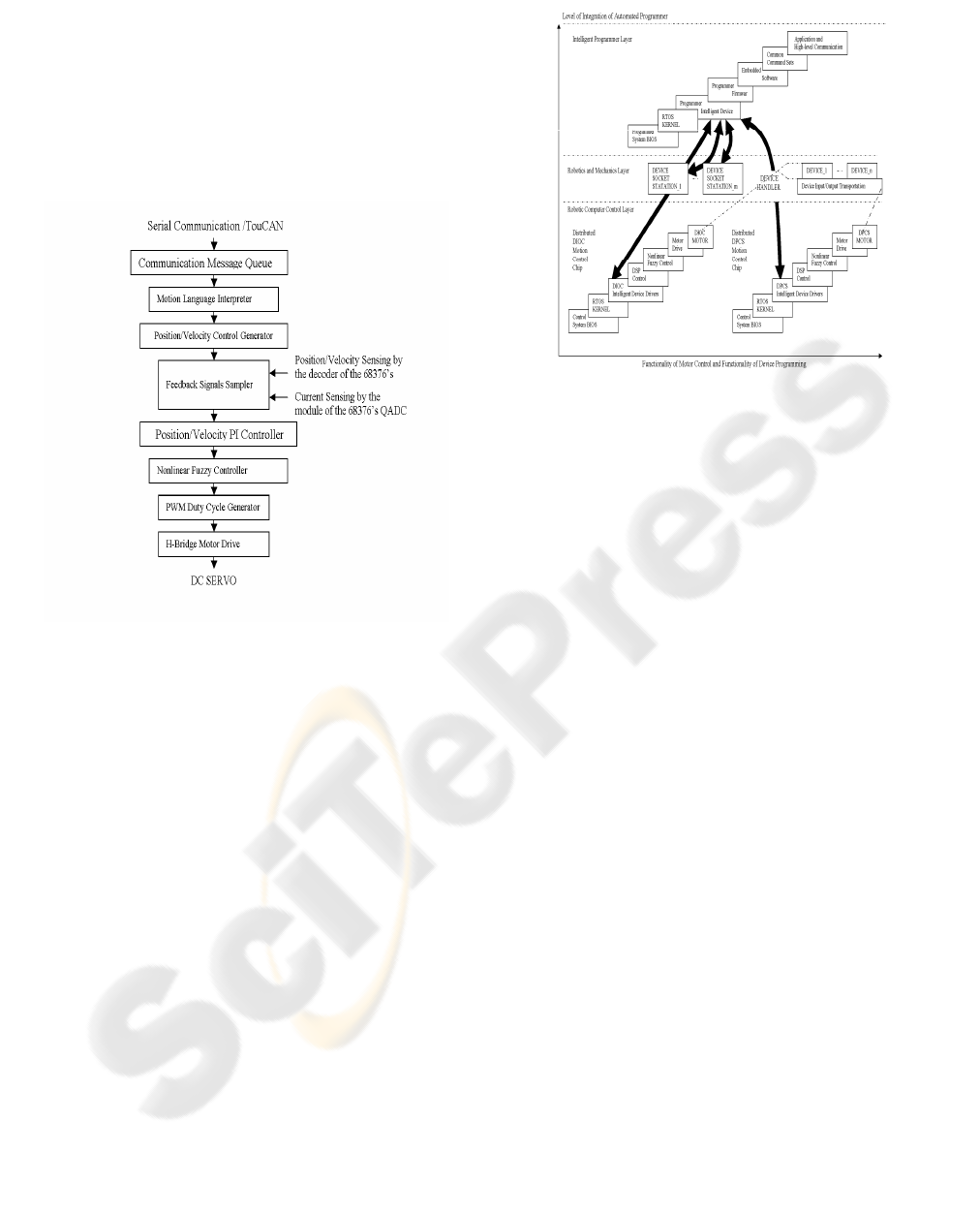
2.4 Integrated Intelligent
Programmer Control System
As discussed in the above Figure 2, both the DPCS
and the DIOC are designed as a distributed
intelligence control structure independently. This
means that the use of single-axis intelligent
controllers which handle the axis of the DPCS and
the axis of the DIOC independently from the
programmer host. This highly flexible solution for
the robotic programmer system, and easily
parameterised for the distributed control of the
motor and the programming of Devices, by uses of
single robotic command language and programmer
command language, it makes the programmer
system to run at non-specialist level. This demands a
completely integrated intelligent programmer (see
Figure 6), which covers the implementation of the
basic motor control functionality and the high-level
modules of the “Motion Control Chip” as shown in
Figure 5, and the implementation of programming
functionality through single programmer command
language.
Figure 6: An integrated intelligent programmer
The integrated intelligent programmer consists of
three layers of integration, i.e., the robotic computer
control layer, the robotics and mechanics layer, and
the intelligent programming layer. The motion
control functionality will be implemented in the
robotic computer control layer; and the device
programming functionality will be implemented in
the intelligent programming layer. The robotics and
mechanics layer will configure all the mechanical
requirements of the transportation of the device
input and output, the device picking and placing
handling, and the device sockets stations. There are
two distributed robotic control subsystems; i.e., the
distributed DIOC motion control chip and the
distributed DPCS motion control chip in an
integrated intelligent programmer. The intelligent
programming layer communicates with the device
sockets station in the robotics and mechanics layer
through the device programming interface, and it
communicates with each distributed motion control
chip in the robotic computer control layer through
host communication interface. The motion control
functionality covers the control system BIOS (Basic
Input Output System), RTOS kernel, intelligent
device drivers, DSP control, nonlinear Fuzzy
control, motor drives, and robotic joint motor. The
device programming functionality covers the
programmer BIOS, RTOS kernel, the intelligent
device drivers, the programmer firmware, the
embedded software, the common command sets, the
application and communication. The common
commands of non-specialist level allow an easy
implementation of a device programming
application in end-customer level using an integrated
intelligent programmer. This structure will eliminate
ICINCO 2005 - INTELLIGENT CONTROL SYSTEMS AND OPTIMIZATION
282

the need to write programming software for the final
user, it also eliminates the need of write DSP code
for robotic motion control. In such cases, the device
will be easily programmed though only setting
device specific parameters and giving non-specialist
common commands to the system. A set of common
language instruction can be defined from a final
user. The common command language syntax is a
mixture between simple memorics similar to
assembler and C language, for instance:
Devices:
DEV PROG; -- program device
DEV ERASE; -- erase device
DEV LOAD; -- load the content of a device
Etc.
Configuration:
STA NO 5; -- set the programming stations 5
SCOKET NO 8; -- set the socket number 8
Etc.
Motion:
ROBOT POS; -- set the robotic position profile mode
ROBOT SPD; -- set the robotic speed mode
HEAD HOME; -- set the end-effector home mode
Etc.
Even if such a language is very advanced and
simplifies all the device programming task of the
end user of the programmer. For a user-friendly
operation environment, we can build a completely
graphical development tools, accompanied by code
generators, thus eliminating the need to write the
code of these command sets. This user-friendly
application interfaces (GUI) can be easily built on a
ColdFusion application dynamic web server, the
designed ColdFusion Components (CFCs) in GUI
framework provide a way to encapsulate device
parameter data and device programming functions in
an object-like manner with inheritance. An end user
of an automated programmer can easily produce any
device programming supports only by clicking
button and filling parameters on Internet remotely or
a local computer.
3 CONCLUSION
In this automated intelligent programmer control
system, the position sensor is needed to measure the
motor angular position; the speed can be estimated
based on position information. The speed control
accuracy of the control system is up to 1/2000
maximum speed in the automations, measured in
LabVIEW 7.0 Professional Development System
(PDS).
Based on the nonlinear fuzzy control
technologies and intelligent integrated automation
strategies for an intelligent programmer application,
applied at embedded system firmware, embedded
software and hardware architecture, together with
advanced DSP micro-controller, this new control
system solution offers many advantages:
(i) Simple self-generation of device programming embedded
software in a user-friendly GUI framework using at non-specialist
level, i.e., software-less device support (no much programming
effort required)
(ii) Flexibility to remote users or local users for programming
device support, having the biggest simplicity of the system
configuration even for the complex programming services,
including consistence of all the components: system hardware,
BIOS, embedded system firmware, and embedded software, and
high-level user application of device programming.
(iii) Implementation of distributed motion control, including a
high accuracy speed digital control and current/torque control
(iv) The implementation of high robot performance in an
intelligent distribution structure, the development of the OOP
embedded software architecture encapsulating all controller
objects and programmer objects of the automated intelligent
system; and simplifying a sophisticated control model for
different robot applications with the utilization of the advantages
of DSP PWM.
(v) University, flexibility, high-performance of device
programming; non-specialists easy access to the intelligent
programmer system, and no need of debugging any embedded
software and hardware, are key features of the intelligent
integrated automated programmer.
REFERENCES
John J. Craig, 1989. Introduction to ROBOTICS
Mechanics and Control, Addison-Wesley Publishing
Company. New York, 2
nd
edition.
William A. Wolovich, 1987. Robotics: Basic Analysis and
Design, CBS College Publishing. New York.
Darley S., Melear C., 1996, An Introduction to the
MC68331 and MC68332, Motorola Inc.
Hassan K. Khalil, 1992. Nonlinear Systems, Macmillan
Publishing Company. New York.
L. A. Zedeh and K. Tanaka et al., 1975. Fuzzy Sets and
their Applications to cognitive and Decision
Processes, Academic Press.
SHIN, K. G. –MCKAY, N. D, 1985, Minimum-Time
Control of Robotics Manipulators with Geometric
Path Constraints. In AC-30 6, pp.531–541, IEEE of
Automatic Control.
SHIN, K. G, 1991. Trajectory Planning for Robot
Control: A Control System Perspective, Control and
Dynamic System Series, Advances in Robotics System,
Academic Press Inc.
EMBEDDED ROBOTIC CONTROL TECHNOLOGIES AND ITS APPLICATIONS IN AUTOMATED
PROGRAMMERS
283
