
A UNIVERSAL MODULAR AUTONOMOUS ROBOT
ARCHITECTURE
Wolfgang Ertel, Joachim Fessler and Nico Hochgeschwender
University of Applied Sciences Ravensburg-Weingarten
Department of Computer Science
Keywords:
Modular robot architecture, interfaces, industry standard, reliability, robustness, middle ware.
Abstract:
We present a universal modular robot architecture. A robot consists of the following intelligent modules:
central control unit (CCU), drive, actuators, a vision unit and sensor input unit. Software and hardware of the
robot fit into this structure. We define generic interface protocols between these units. If the robot has to solve
a new application and is equipped with a different drive, new actuators and different sensors, only the program
for the new application has to be loaded into the CCU. The interfaces to the drive, the vision unit and the other
sensors are plug-and-play interfaces. The only constraint for the CCU-program is the set of commands for the
actuators.
1 INTRODUCTION
In the literature many approaches for software-
modularity (Corder et al., 2002), hardware-
modularity (Guilin and Chen, 2000) and framework
projects exist.
Two particularly interesting framework projects are
Player/Stage (Vaughan et al., 2003), which comes
with a nice simulation environment, and the compo-
nent based system Orca (Brooks et al., 2005) with
special modularity features. While these systems are
mainly focused in software modularity in our ap-
proach we provide methods for a smooth combination
of software- and hardware-modularity.
1.1 Overview of the Architecture
As shown in figure 1 the hardware of the robot con-
sists of five flexibly exchangeable parts or groups of
parts. The mechanical structure provides an easy way
of exchanging these hardware modules. The archi-
tecture comprises a central control unit, a drive, a vi-
sion unit and a sensor input unit and an actuator unit,
which work as follows.
Central control unit (CCU): This unit contains a
powerful embedded PC-board running linux with
all standard interfaces such as USB, AGP, firewire,
ethernet, wlan, PC-card-slots and its own power
supply built in a rugged cage with many slots and
mountings. In order to exchange information with
all the other components in a simple and uniform
way, a CAN bus (Etschberger, 2002) acting as the
information backbone completes this module. The
high level intelligence utilizing machine learning
techniques on the behaviour level of course is ap-
plication dependent and at least parts of it have to
be exchanged for new applications.
Vision unit: A VGA color CCD-camera is con-
nected via firewire to a graphic processing unit
which does the low level image processing. The
high level image processing includes detection of
objects, lines, structures as well as mapping, track-
ing and positioning of the robot. For this resource
comsuming task we spend a second embedded PC-
board. The software interface between the vision
unit and the CCU is the world model consisting of
coordinates, shape, size and speed of all detected
objects, which will be described in section 2. In
subsection 2.1 we describe a concept which allows
for an easy replacement of the vision unit by a dif-
ferent one, for example a stereo vision unit.
Drive: The drive of the robot drive must be easily ex-
changeable. Drive replacement is based on a fixed
high level protocol for motion commands which
have to be interpreted by the intelligent microcon-
troller of the drive unit.
Sensor input: Due to the flexible mounts at the cage
391
Ertel W., Fessler J. and Hochgeschwender N. (2005).
A UNIVERSAL MODULAR AUTONOMOUS ROBOT ARCHITECTURE.
In Proceedings of the Second International Conference on Informatics in Control, Automation and Robotics - Robotics and Automation, pages 391-394
DOI: 10.5220/0001164903910394
Copyright
c
SciTePress
of the CCU and the drive, various secondary sen-
sors can easily be attached on any side or on top
of the robot. Depending on the particular task each
sensor may communicate via the CAN bus either
with the CCU, vision unit or even directly with the
drive.
Actuator(s): Actuators have to be connected via the
CAN-bus. A well defined and fixed set of (low-
level) action commands to be sent from the CCU
to the actuators is the basis for easy replacement of
actuators.
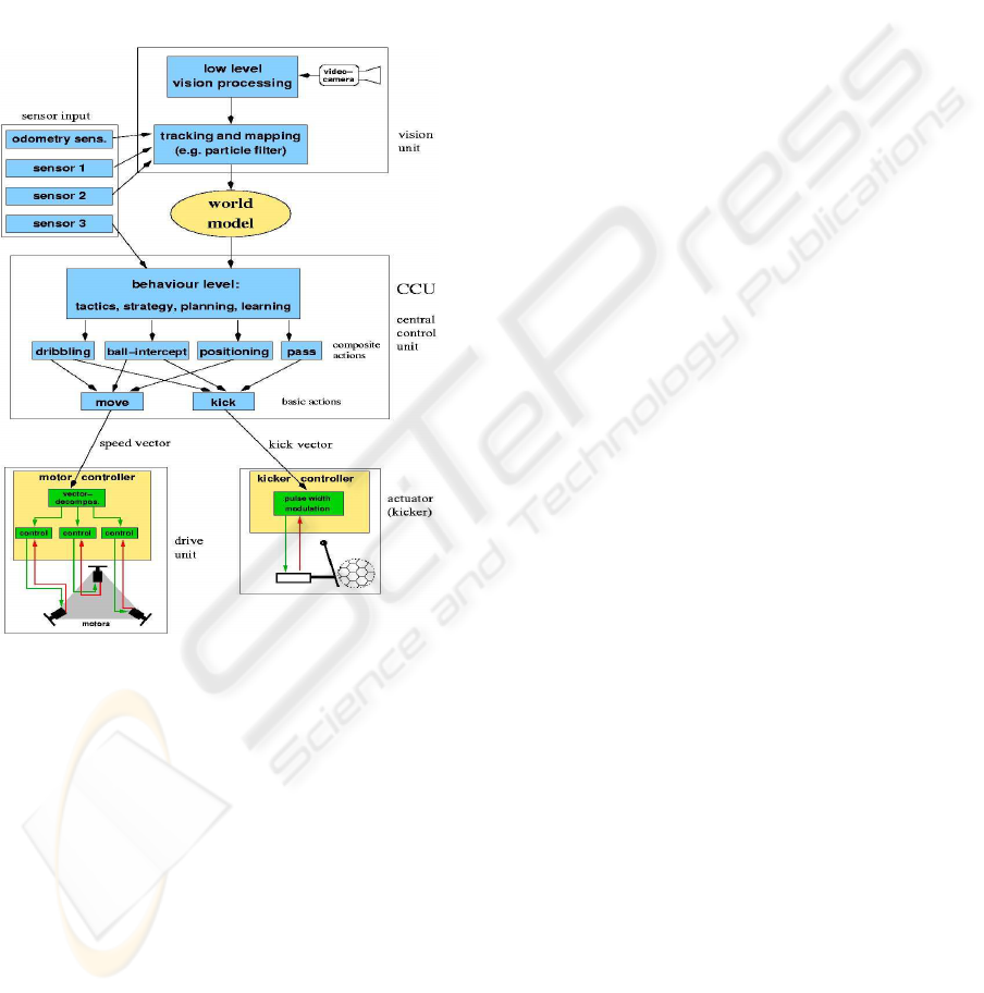
Figure 1: A robot soccer player as an example for the func-
tional structure of the modular robot architecture.
2 SOFTWARE ARCHITECTURE
A reconfigurable robot hardware needs on the soft-
ware side a flexible and modular architecture. To
achieve this goal we need a middleware which bridges
the gap between operating system and applications.
Our object oriented software architecture is based
on linux and the ICE middleware (Henning and
Spruiell, 2004). The Internet Communication Engine
(ICE) gives us the possibility to develop autonomous
software modules with different programming lan-
guages e.g Java, C++ and Python.
As shown in figure 1 the software architecture is
divided into a vision unit with low- and high level
processing, a world model and a central control unit
(CCU) for planning the actions of the robot.
2.1 Software Modularity
Suppose we have configured the five units of the robot
to solve a particular task. If we now want to reconfig-
ure the system for a new, completely different task,
we may for example need a different drive and a dif-
ferent actuator. Of course for a new task the software
of the CCU has to be replaced by a new one.
For exchanging the drive, due to the application in-
dependent fixed interface between CCU and drive, we
just attach any new drive (with its built in motor con-
troller) to the robot with no software changes at all in
the CCU or in the motor controller. Thus exchanging
drives works in a plug-and-play manner.
The interface between CCU and the actuator(s) is
more complex, because the commands to the actu-
ators are application specific. This means that the
CCU must send only commands which the actuator(s)
can interpret. The CCU programmer of course has
to know the actuator commands before programming
any actions.
The interface between CCU and the vision unit
seems to be even more complex because both units
have to use the same structure of the world model.
Thus, at least the mapping and tracking part of the vi-
sion unit has to be reprogrammed for every new CCU
software. A solution for this problem is based on a
generic vision unit which is able to detect objects
with a wide range of different shapes and colours.
When the CCU and the vision unit are connected,
they start an initial dialogue in which the CCU sends
a specification of the required world model structure
to the vision unit. For example in a soccer applica-
tion the CCU may send an object-description-list with
items like
object("ball", moving,
geometry(circle(20,25)),
color([0.9,1],[0.7,0.8],[0,0.5]),
object("goal1", fixed,
geometry(rectangle(200,100)),
color([0,0.3],[0,0.3],[0.9,1]),
describing an object “ball” as a moving object with
the shape of a circle, a diameter between 20 and 25
cm and orange colour. “goal1” is a fixed blue 200 ×
100 cm rectangle. After this initialization, when the
robot starts working, in each elementary perception-
action-cycle the vision unit tries to detect objects of
the types specified by the object-description-list and
returns them together with their current position. For
example in the simplest case the vision unit sends a
list like
detected("ball", pos(2.47,11.93)),
detected("goal1", pos(5.12,3.70)),
to the CCU. This description may be more com-
plex, including for example the size and color of the
ICINCO 2005 - ROBOTICS AND AUTOMATION
392
detected objects. This protocol allows us to work with
the same vision unit for a large class of different con-
trol units and the interface between CCU and vision
unit becomes a plug-and-play interface.
With other sensors like infrared detectors which are
simpler than a CCD-camera this interface may be-
come simpler, but nevertheless it may use the same
object description language.
2.2 The Vision Unit
The vision unit is an autonomous software module re-
sponsible for low level and high level image process-
ing.
Low Level Processing: In this unit we use the power
of a common Graphic Processing Unit (GPU) to ex-
tract information about the relevant objects from a
raw picture. We developed a library which has im-
plementations for standard image processing tasks
like normalization of a picture which is useful for
many mobile robot applications.
High Level Processing: Based on the data from the
low level processing unit and the odometry the high
level processing unit is responsible for more intel-
ligent and complex tasks such as self localization
and mapping using a particle filter (S. Thrun and
Dellaert, 2001).
2.3 The World Model
The derived information from the high level vision
processing unit is saved in a data structure called
world model. The world model contains information
about position, velocity and acceleration of the robot
and detected obstacles. It forms the basis for decision-
making in the central conrol unit.
2.4 The Central Control Unit
The central control unit (CCU) as shown in figure 1
provides the “intelligence” of the robot. It is struc-
tured in three levels of functions. The lowest level
of basic actions outputs the control-commands for
the drive or the actuators. The inputs for these basic
actions are very simple. For example the call of the
“move”-action of a robot as described in section 3.3
may be move(2.4,35,0), meaning, that the robot has to
accelerate with 2.4m/s
2
in the relative direction 35
◦
with no rotation of its body, i.e. the alignment does
not change.
The next level of composite actions aggregates a
sequence of basic actions, which may form quite com-
plex motion pattern. For example dribbling from po-
sition A to position B (while guiding the ball) is a
composite action. In complex cases like this, pro-
gramming an optimal motion sequence may become
very hard, especially because we have no formal
model of the motion sequence. Therefore machine
learning techniques, such as reinforcement learning
have to be used in order to optimize these composite
actions.
At the top level, the behaviour of the agent has to
be implemented. A wide variety of techniques from
artificial intelligence can be applied, depending on the
particular application. In many cases, supervised ma-
chine learning methods such as neural networks or de-
cision trees may be applied if training data are avail-
able.
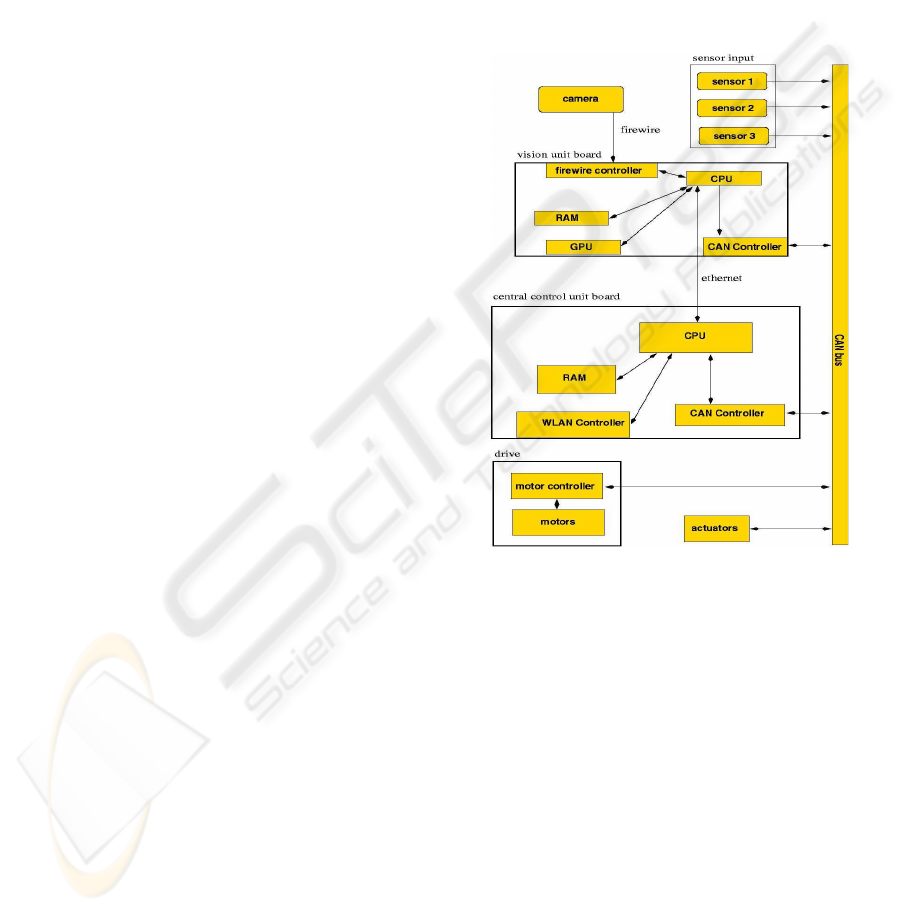
Figure 2: Hardware architecture of the mobile robot.
3 HARDWARE ARCHITECTURE
As shown in figure 2 the top level interconnection
structure of the hardware modules is identical to that
of the software modules described in section 2. To
increase CPU performance and support modularity of
the system the vision unit and the central control unit
are distributed on two PC-boards.
3.1 Vision Unit
We use a color CCD camera to capture the pictures
of the environment. The CPU sends the picture to
the graphic processing unit (GPU) which executes the
low level vision processing with a high degree of par-
allelism resulting in high performance. The high level
A UNIVERSAL MODULAR AUTONOMOUS ROBOT ARCHITECTURE
393

vision processing and mapping as described in sec-
tion 2.2 is performed on the CPU of the vision board.
3.2 Central Control Unit
The CCU receives the world model data from the vi-
sion unit via ethernet and computes the actions of the
robot e.g. motion and the activity of the actuators.
The commands for the motion and the actuators are
sent via a controller area network (CAN) controller to
the different devices.
3.3 Drive
Robot drives are designed for special environments,
e.g. for indoor activities like robot soccer or for out-
door activities like rescue applications. According to
the specification of the environment a wide range of
drives is available. If a robot should work in differ-
ent environments the possibility to easily exchange
the drive is essential.
One requirement to run a robot with an exchange-
able drive is a well defined interface between the cen-
tral control unit (CCU) and the drive. The second goal
is to have all the motion control software on the drive
unit to make the CCU and the drive unit independent.
We designed the interface such that the CCU asyn-
chronously sends an array of three values to the drive.
This array contains the desired acceleration value, the
relative motion direction (relative to its current head-
ing) and the new alignment of the robot relative to
its current alignment. In some applications it may be
sufficient to simply ignore the alignment angle. In
others, however, the low level move-command in the
CCU (section 2.4) has to be replaced.
To guarantee the required modularity (all low level
movement control loops must be implemented in the
drive) the drive must have its own CPU and a odome-
try system.
3.4 Actuators
The modular structure allows to add different actua-
tors to the robot. To guarantee a maximum of flexi-
bility an actuator-language with a fixed low level in-
struction set must be designed. This set must contain
a number of universal instructions like grab, release,
drop, hold, push, pull or kick.
4 CONCLUSION
We introduced a modularized flexible robot architec-
ture. All hardware and software parts are exchange-
able. To modify the robot for a special application
drive, vision unit, sensors and actuators may be re-
placed by different (intelligent) devices. On the soft-
ware side only the central control unit (CCU) has to
be adjusted. However, there are limits to this flexibil-
ity. The long term experimental evaluation will show
where these limits are. For the future we would like
to develop hardware components that adapt to each
other by means of machine learning techniques.
REFERENCES
Brooks, A., Kaupp, T., Makarenko, A., Williams, S., and
Orebck, A. (2005). Towards component-based robot-
ics. In Proceedings of the IEEE/RSJ International
Conference on Intelligent Robots and Systems.
Corder, J., Hsu, O., Stout, A., and Maxwell, B. A. (2002). A
modular software architecture for heterogeneous robot
tasks. In AAAI Mobile Robot Competition & Exhibi-
tion Workshop. AAAI Press.
Etschberger, K. (2002). Controller-Area-Network. Fach-
buchverlag Leipzig.
Guilin, Y. and Chen, I.-M. (2000). Task-based optimiza-
tion of modular robot configurations - mdof approach.
Mechanism and Machine Theory, 35(4):517–540.
Henning, M. and Spruiell, M. (2004). Distributed Program-
ming with Ice. http://www.zeroc.com.
S. Thrun, D. Fox, W. B. and Dellaert, F. (2001). Robust
monte carlo localization for mobile robots. Artificial
Intelligence, 128(1-2):99–141.
Vaughan, T., Gerkey, B., and Howard, A. (2003). On device
abstractions for portable, reusable robot code. In Pro-
ceedings of the IEEE/RSJ International Conference on
Intelligent Robots and Systems.
ICINCO 2005 - ROBOTICS AND AUTOMATION
394
