
CONTROL SYSTEM INTERFACE OF SCANNING SONAR FOR
MOBILE ROBOTS
Sv. Noykov and O. Manolov
Laboratory of Mobile Robotics LAMOR, ICSR-BAS, Block 2, Acad. G. Bontchev St., Sofia 1113, Bulgaria
Keywords: Mobile robot, Ultrasonic rang
e-finder.
Abstract: In this work, a simple, low-cost and reliable electronic module for coupling of an ultrasonic range-finder
with a mobile robot’s microprocessor system is presented. A software filter for correct reading of the
ultrasonic data is presented as well. Due to the software filter, a shielding of robot and sonar’s electronic
modules is not required. In this way compactness and low price of the device construction were achieved.
1 INTRODUCTION
Ultrasonic range-finders, referred also as sonars, are
known as robust and cheap distance measurement
devices suitable for various applications (Corrion et
al., 1996), including gathering of information from
environment for real-world modeling as well as for
navigating in mobile robotics (Borenstein et al.,
1996; Cao and Borenstein, 2002; Noykov and
Manolov, 2004). Ultrasonic range-finders don’t
depend on the lighting and brightness of surfaces,
even if they are influenced by the matter in which
the objects are made; they don’t depend on smoke,
and they don’t need cumbersome equipment
(Corrion et al., 1996). These devices provide relative
distance measurements between them and
surrounding obstacles located within their angular
detection range, also called “sonar detection cone”.
The time elapsed between the transmission of a
wave and the reception of its echo allows the
computation of a range reading r.
The current market suggests a variety of
u
ltrasonic range-finders. As is reported in
(Borenstein et al., 1996), the ultrasonic range
finders, based on POLAROID ranging modules, are
the most widely found in mobile robotics literature.
The base series of POLAROID ultrasonic ranging
systems is described in (Borenstein et al., 1996;
Polaroid Corp., 1991; Polaroid Corp., 1981). It
includes transducer and two electronic modules:
ranging circuit board and experimental
demonstration board. This ultrasonic ranging system
is low cost and its parameters satisfy the
requirements of the most applications in mobile
robotics (Borenstein et al., 1996). It is able to
measure ranges from 0.9 feet to 35 feet with
resolution 0.1 feet. The ranging circuit board (RCB)
controls both the transmit and receive operating
modes of the transducer. The experimental
demonstration board (EDB) is designed especially
as a user interface to the RCB. The EDB contains all
the necessary electronic circuitry to convert the
transmit/receive time interval into a figure indicating
distance, in feet, and present it on a three digit light
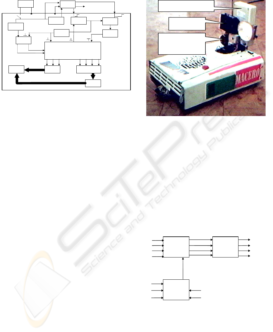
emitting diode (LED) display. The block diagram of
the EDB, given in (Polaroid Corp., 1981), is shown
in Fig. 1. The output of the EDB is a three digit
display (9) with a numeric output range of 0.9 to
35.0 in increments of 0.1 feet. The multiplexed
display is controlled by a three-digit binary counter
(8) with strobed digit-select lines DS1, DS2, DS3. It
uses a single binary-coded decimal (BCD) to-7-
segment decoder (11). Unfortunately, this
multiplexed display output does not allow direct
coupling with external microprocessor system. For
this purpose, an additional interface circuitry is
required. Such interface equipment, given in
(Ciarcia, 1980), was manufactured and tested in
Laboratory of Mobile Robotics LAMOR, ICSR-
BAS. Unfortunately, it was established that this
interface circuitry did not work properly.
245
Noykov S. and Manolov O. (2005).
CONTROL SYSTEM INTERFACE OF SCANNING SONAR FOR MOBILE ROBOTS.
In Proceedings of the Second International Conference on Informatics in Control, Automation and Robotics - Signal Processing, Systems Modeling and
Control, pages 245-250
DOI: 10.5220/0001164302450250
Copyright
c
SciTePress
RCB
POWER
+6V
GND
VDD
transducer
VSW XLG FLGGND
ON/OFF
1
2
SET
RES
RES
SET
3
4
LE
7
DLE
6
5
CLK RES
A1 A7
OF
178 ms
LC
SR
RES LATCH
ENABLE
SCANNING CLOCK
CLK INPUT
8
DS3 DS2 DS1 Q3 Q2 Q1 Q0
9 10
11
12
Sonar’s
transducer
Camera
Radiomodem
Figure 1: Block diagram of the Polaroid Experimental
Demonstration Board
In this work, hardware and software devices,
which enable an external microprocessor system to
read correctly the information from a POLAROID
ultrasonic ranging system, are presented.
Figure 2: The mobile mini-robot LAMOR-1TV.
2 THE SCANNING ULTRASONIC
RANGE-FINDER
In the LAMOR Lab, ICSR – BAS, the mobile robot
LAMOR-1TV has been created for experimental
research and education. LAMOR-1TV, shown in Fig.
2, is described in (Noykov and Manolov, 2004).
LAMOR-1TV is a mobile mini-robot with differential
steering. LAMOR-1TV has a length of 400 mm, a
width of 260 mm and a height of 220 mm. As part of
sensor subsystem of the robot, a scanning ultrasonic
range-finder (shortly sonar) was developed. The
sonar is based on an ultrasonic ranging system from
the base series of POLAROID. To enable scanning,
the transducer of the sonar is mounted on the axle of
a stepper motor. The home angular position of the
sonar’s transducer is 0º, i.e., the sonar’s transducer is
directed to the robot’s front in its home position. The
scanning range of the sonar is 244.8º, starting from -
122.4° to +122.4° in the horizontal surface. The
minimum scanning angle step of the sonar is 1.8º.
The described in the next section interface module
IM is used for coupling of the sonar with the
LAMOR-1TV microprocessor system.
3 INTERFACE MODULE FOR
CONNECTION OF AN
ULTRASONIC RANGING
SYSTEM TO AN EXTERNAL
MICROPROCESSOR SYSTEM
The suggested in (Ciarcia, 1980) interface circuitry
was modified and new interface module for coupling
of an ultrasonic ranging system from the base series
of POLAROID with an external microprocessor
system was developed. The block diagram of the
Q0
Q1
Q2
Q3
BIT3
BIT2
BIT1
BIT0
DS3
DS1
DS2
BIT1
BIT0
X0
X1
X2
B
A
D0
D1
D2
D3
CK
1
23
O
UTPU
T
BIT1 BIT0 LIN
E
0 0 DS1 (LSD)
0 1 DS2
1 0 DS3 (MSD)
Figure 3: Interface module for connection of an ultrasonic
ranging system POLAROID to an external micro
p
rocesso
r
system: block diagram
ICINCO 2005 - SIGNAL PROCESSING, SYSTEMS MODELING AND CONTROL
246
IC3C CD4050
7
6
IC2 CD4052
12
14
15
11
1
5
2
4
6
10
9
13
3
7
X0
X1
X2
X3
Y0
Y1
Y2
Y3
EN
A
B
X
Y
VEE
DS2
IC4B
CD4070
5
6
4
Q3
BIT1 out
Q0
IC3B CD4050
5
4
DS1
IC3D CD4050
9
10
Q2
BIT0 out
BIT3 out
C1 100pF
IC3A CD4050
3
2
BIT0 in
BIT2 out
IC1 CD4042B
4
7
13
14
5
6
3
9
12
15
2
10
11
1
D0
D1
D2
D3
CLK
POL
Q0
Q1
Q2
Q3
Q0
Q1
Q2
Q3
IC4A
CD4070
1
2
3
DS3
+5V
BIT1 in
Q1
R1
10k
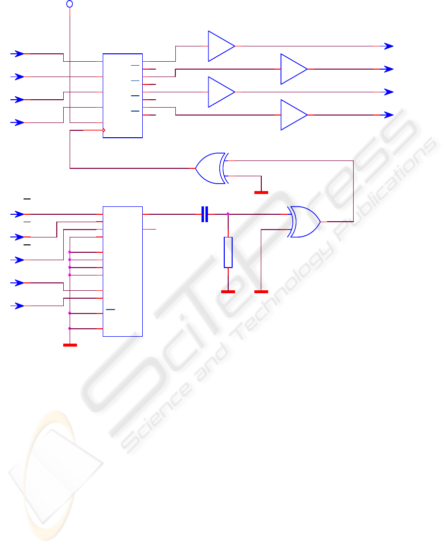
Figure 4: Interface module for connection of an ultrasonic ranging system POLAROID to an external microprocesso
r
system: schematic diagram
interface module (IM) in Fig. 3, its schematic
diagram in Fig. 4, and its timing diagram in Fig. 5,
are shown.
The block diagram of the interface module (IM)
includes three blocks. Block 1 includes three-input
demultiplexer (IC2) and logic circuits for a strobe
signal generating (IC4). Block 2 includes a 4-bit lach
(IC1), and Block 3 includes an output buffer (IC3).
When the MSD (most-significant digit) of the LED
display is energized, the DS3 line is low. The data
on Q0 thru Q3 at this tame form the BCD value of
that number. Similarly, when DS2 goes low, the data
lines will hold the second digit value. IC2 is a 4-to-
1-line demultiplexer with the three digit strobes as
inputs. A 2-bit TTL compatible parallel output from
the reading external microprocessor system
determines which of these channels is routed though
the multiplexer. To get DS1, the LSD (least
significant digit), the input code to the EDB
interface would be 00. A binary code of 10 would
set channel 3, allowing DS3 to go through. A
summary of the codes is given in the table showed in
Figure 2.2a. When we have selected which digit we
want to read by setting the proper multiplexer-input
code, that digit value will be latched into IC1 and
available as a BCD value to the reading external
microprocessor system. IC3 buffers the CMOS
voltage levels of the EDB to the TTL level required
by some microprocessor systems. To obtain the
distance indication, it is necessary to add the three
values:
DISTANCE = (MSD)*10+(2
nd
digit)*1+(LSD)*0.1
CONTROL SYSTEM INTERFACE OF SCANNING SONAR FOR MOBILE ROBOTS
247
4 THE SOFTWARE FILTER FOR
CORRECT READING OF THE
SONAR INFORMATION
During preliminary experimental gathering of
information from laboratory environment by the
mobile robot LAMOR-1TV, equipped with the
presented in Section 2 sonar, we found that the
robot’s microprocessor system did not read sonar
data correctly, due to the mutual influence of the
electromagnetic fields of the near located circuit
boards of the robot, circuit boards of the sonar, IM,
and stepping motors. Instead of shielding, we
developed a software filter for correct reading of the
sonar information by the robot’s microprocessor
system. The objectives that we had to achieve were
compactness and low price of the construction.
Initially we accomplished number experimental
readings by the sonar. Afterwards we analyzed the
stored in robot’s memory sonar information, read by
robot’s microprocessor system. It was found that this
information contained alternated sequences of
correctly and wrongly received data. The durations
of these sequences were analyzed. Afterwards, on
the basis of obtained results, a software filter was
developed, and implemented as executable code,
written in the on-board EPROM memory of the
robot.
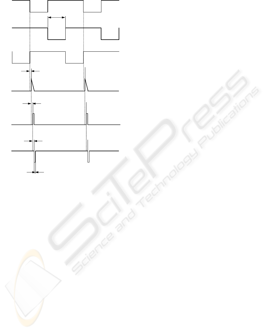
DS1
DS2
DS3
IC4A,
p
in 1
IC4A,
p
in 3
IC4B,
p
in 4
t
p,IC2
t
p,IC4A
t
p,IC4B
t
W
t
DS
The algorithm of the software filter is
represented in Fig. 6. The calling subprogram
requires LSD, 2
nd
digit, and MSD of sonar data from
the called subprogram consecutively. The called
subprogram reads the data of required digit
repeatedly. To validate the read digit, a coincidence
of 100 consecutive readings is required. After the
read digit is validated, the called subprogram sends
it to the calling subprogram. A single reading takes
34 µs; therefore 100 consecutive readings take 3.4
ms. In the best case (i.e., in case without wrongly
read data) the acquiring of all three sonar digits will
take 3*3.4=10.2 ms. We found that in the worst case
the acquiring of all three sonar digits will take 19.1
ms.
5 IMPLEMENTATION
In (Noykov and Manolov, 2004), we proposed a
modified method for occupancy grid map building
by a mobile robot and a scanning ultrasonic range-
finder. The map building process consists of two
phases: 1) Gleaning of information from
environment, and 2) Sonar data processing. For
sonar data processing the proposed modified method
combines: 1) statistical approach for probability
sonar model building; and 2) application of the
fuzzy logic theory for sonar data fusion. For
experiments, the mobile robot LAMOR-1TV,
equipped with the scanning sonar, is used. The
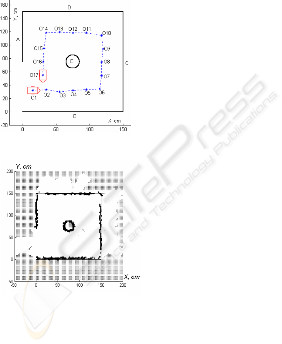
experimental laboratory environment is presented in
Figure 7. The experimental laboratory environment
is characterized by two book shelves A and B, with
rough surfaces, which may cause a smooth sonar
echo, and two walls C and D, with flat surfaces,
which may induce multiple reflections. The
environment involves also a stationary cylindrical
object E. The executed robot path is depicted by
dotted line. Successive positions, where the robot
stops and collects information from environment by
scanning range finder, are O
1
, O
2
... O17. They are
labelled by stars. The robot is shown in its both start
position O
1
and end position O
17.
Figure 5: Interface module for connection of an
ultrasonic ranging system POLAROID to an external
microprocessor system: timing diagram
The algorithm for gleaning of information from
environment by moving mobile robot and scanning
ultrasonic range finder is as follow:
ICINCO 2005 - SIGNAL PROCESSING, SYSTEMS MODELING AND CONTROL
248
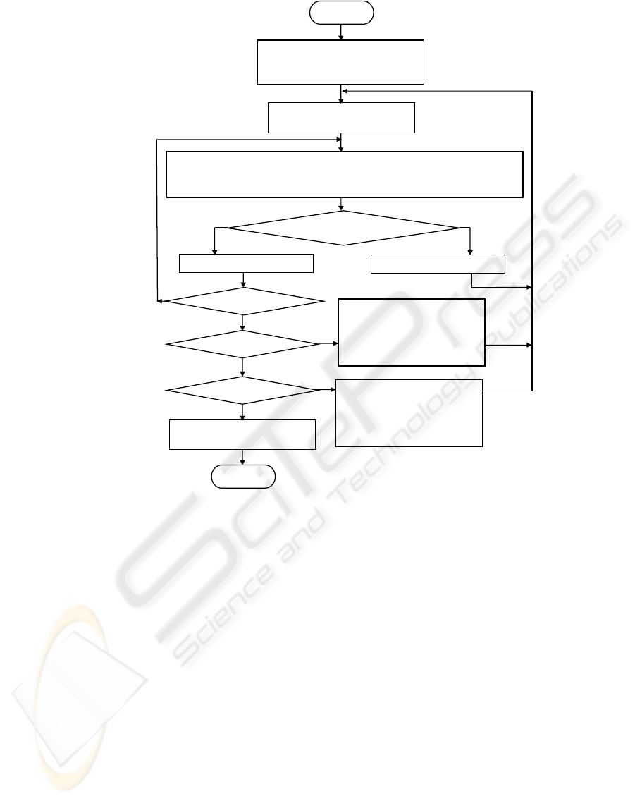
N
Y
Y
N
N
Y
N
Read sonar data digit according to value of CODE. Compera read digit
DATA
new
with last read value DATA
old
DATA
new
== DATA
old
?
Clear counter COUNT:
COUNT= 0
DATA
old
= DATA
new
COUNT= COUNT+1
COUNT==100?
In
p
ut
Establish code for LCD reading:
CODE= 0
CODE==0?
Save in memory LCD.
Establish code for 2
nd
digit
reading:
CODE= 1
Save in memory 2
n
d
digit.
Establish code for MCD
reading:
CODE= 2
Save in memory MCD
Out
p
ut
Y
CODE==1?
Figure 6: The algorithm of the software filter.
1) The robot stops in the point О
к
. The sonar rotates
in its end right angular position (-122.4°) and takes a
measurement
. The counter is established i= 1.
k
i
r
2) The counter is incremented, i= i+1. The sonar
rotates one step to the left and takes a
measurement
.
k
i
r
3) Step 2 repeat while sonar reaches its end left
angular position (+122.4°).
4) The sonar rotates in its home position (0º) and the
robot goes to the next path point, O
k+1
.
5) Algorithm 1) - 4) repeated while the robot reaches
the end of the planned path.
A program, written in the EPROM of the on-
board microprocessor control unit, carries out the
immediate servicing and control of the LAMOR-1TV
sensors and motors. This program accomplishes also
the communication with external PC through RS232
interface, where the high-level robot control
program is written in C. The high-level robot control
program enables the user to program the robot’s
path, co-ordinates of the positions, where the robot
must stop and collect information from environment,
scanning angle step of the sonar, etc. Range finder
data are collected in the robot’s frame of reference
by scanning a space around the robot’s instant
position O
i
, passed to the external PC, and stored
there into a text file.
One of the experimentally obtained cell maps of
the environment from Figure 5 is presented in Figure
8. The occupied cells are labelled by thick black
crosses and small points label the indeterminate
cells. It can be seen, that: 1) regardless of the
different roughness of the object surfaces, the
thicknesses of the object contours are approximately
equal; and 2) the wrong measurement results due to
multiple reflections are rejected.
CONTROL SYSTEM INTERFACE OF SCANNING SONAR FOR MOBILE ROBOTS
249
6 CONCLUSION
In this work, hardware and software devices, which
enable a robot’s microprocessor system to read
correctly the information from scanning sonar, based
on a POLAROID ultrasonic ranging system, are
presented. The interface includes a simple, low-cost
and reliable electronic module for coupling of the
ultrasonic ranging system with the robot’s
microprocessor system, and a software filter for
correct reading of the information passing between
them. Due to the software filter, a shielding of robot
and sonar’s electronic modules is not required. In
this way compactness and low price of the device
construction were achieved.
REFERENCES
Borenstein, J., H.R.Everett, L.Feng, 1996. "Where am I?”
Sensors and Methods for Mobile Robot Positioning.
Technical Report. The University of Michigan.
Cao, A., and J. Borenstein, 2002. Experimental
Characterization of Polaroid Ultrasonic Sensors in
Single and Phased Array Configuration. Presented at
the UGV Technology Conf. at the 2002 SPIE
AeroSense Symp., Orlando, FL, April , 1-5.
Figure 7: Gleaning of information from
environment by moving mobile robot and scanning
ultrasonic range finder: experimental laboratory
environment and robot path.
Ciarcia, S., 1980. Home In on the Range! An Ultrasonic
Ranging System. Byte Publications Inc.
Corion, O., A.M.Desodt, D.Jolly, 1996. Using Ultrasonic
Means for the Recognition of a Real Space. Proc. 6th
International Symp. on Int. Measurement
Confederation “Eurotech ‘96”, Brussels, 9-11 May,
pp. 415-420.
Noykov, Sv., O. Manolov, 2004. Environment Map
Building Using Mobile Robot and Ultrasonic Range
Finder. In 5-th IFAC Symposium on Intelligent
Autonomous Vehicles, Lisbon, Portugal, July 5-7, CD-
ROM paper No 388.
Polaroid Corporation, 1991. Ultrasonic Ranging System.
Product Literature, Polaroid Corporation, 784
Memorial Drive, Cambridge, MA 02139, 617-386-
3964.
Polaroid Corporation, Commercial/Battery Division, 1981.
Polaroid Ultrasonic Ranging System. Handbook
Application Notes/Technical Papers.
Figure 8: An experimentally obtained integrate
d
occupancy grid map of the environment, represented i
n
Figure 7. The empty cells are leaved by white; thic
k
black crosses label the occupied cells; and small points
label the indeterminate cells.
ICINCO 2005 - SIGNAL PROCESSING, SYSTEMS MODELING AND CONTROL
250
