
PRIMOS – A NOVEL CONCEPT TO PROGRAM COMPLEX
ASSEMBLY PROCESSES
Markus Ehrmann, Jochen Schlick, Marc Seckner, Detlef Zuehlke
Institute for Production Automation, Kaiserslautern University of Technology,
P.O. Box 3049, 67653 Kaiserslautern, Germany
Keywords: Robot programming, visual programming, micro assembly, interference handling.
Abstract: Over the past years requirements and size of robot programs have continuously increased. Especially
assembly processes increasingly integrate sensors and sensor-based positioning methods to ensure safe
processes. Until now programming is realized in manufacturer-dependent text-oriented or graphic-supported
simulation systems. If such complex processes have to be realized, both methods result in various
disadvantages: Text-oriented programs loose their overview and simulation systems are in need of entire
environment models. Due to these reasons, a new concept has been developed in order to improve and
simplify the programming of complex sensor based assembly processes. The main objectives of the concept
are reducing complexity of robot programs, facilitating clearness for users, supporting diagnostics and
handling of trouble during programming. Therefore the technique of visual programming is used and the
program is described in an abstract manner by linking graphical symbols. They represent movement of
robots and positions of endeffectors. To execute various tasks, so called actions are assigned to the program
flow. Further on a concept for handling occurring troubles is integrated. So called exceptions are user-
defined and consist of various types of troubles. If an exception is triggered, the program flow will be
interrupted and reactions take place. For validation, the concept has been successfully implemented in a
tool, named PRIMOS (P
rogramming Robots with an Interference Handling Motion Orientated System). It
has been positively evaluated by programming a sensor based assembly process of flanges on optical fibres.
1 INTRODUCTION
Industrial robots constitute an important factor in
factory automation (Wörn, 2003). They are used in a
various fields and applications. Up to now most of
them are installed in mass-productions like the
automotive industry (Krause, 1998; Wörn, 1998;
Weck, 2001). In modern automotive plants they are
commonly used for welding and component
handling (Wörn, 1998). While offering high
potential for cost reduction in automated
manufacturing, they are a considerable expense
factor. Capital investment and maintenance costs can
be estimated easily, but the expenses for
programming are difficult to assess (Denkena, 2004;
Zäh, 2004).
Programming includes generating program code,
optimizing program code, teaching point
coordinates, adapting programs and of course
educating robot programmers (Denkena, 2004;
Blume, 1996). Consequently the time needed for
programming is an important cost factor.
Investigations figured out that the ratio of
programming time to production time can rise up to
50% (Zäh, 2004). An important influence to the
programming time needed is the complexity of the
program which is affected by the requirements of the
task and the amount of integrated devices like
sensors or other robots (Rosenbusch, 2003; Weck,
2003).
The complexity of robot programs keeps increasing
during the past years. This is due to rising demands
to geometrical tolerances, reliability, cycle times etc.
To fulfil these demands intelligent devices, sensors
and sensor-based positioning methods are used
(Hirziger, 1999). The complexity of the program
code rises because control-loops, synchronization
with external intelligent devices and device access
functions have to be implemented. In most cases the
code is very problem specific and can’t be reused in
other programs.
The complexity of the process and the program code
lead to a certain susceptibility to troubles. Hence a
concept for interference handling has to be
107
Ehrmann M., Schlick J., Seckner M. and Zuehlke D. (2005).
PRIMOS – A NOVEL CONCEPT TO PROGRAM COMPLEX ASSEMBLY PROCESSES.
In Proceedings of the Second International Conference on Informatics in Control, Automation and Robotics - Robotics and Automation, pages 107-112
DOI: 10.5220/0001162801070112
Copyright
c
SciTePress
integrated in the programs to ensure safe processes.
However this increases the complexity of the
program code even more.
In this paper a new concept for programming robots
is presented, which helps to reduce the complexity
of the program code and helps to keep an overview
of the program. The advantages of visual
programming are combined with an intuitive and
easy way to integrate sensors, control-loops and
sensor based positioning methods. A major
component that settles on top of the sensor
integration is an exception handling concept. So,
inevitable trouble during the process can be easily
handled. The concept has been implemented in a
tool named PRIMOS (P
rogramming Robots with an
I
nterference Handling Motion Orientated System).
2 MOTION ORIENTED
PROGRAMMING
To guarantee an easy and intuitive use,
programming is carried out with the technique of
visual programming. This technique is used in a lot
of software applications and offers various
advantages (Möbius, 1996; Schiffer 1998; Schröder
2000; Bischoff 2002; Zühlke, 1997). Visual
programming represents elements in an abstract
manner by graphical symbols. Compared to
graphical programming there is no need for CAD-
models of the environment. The program to be
created is displayed with a focus on the robot’s
motions and the endeffector’s positions. The motion
flow of the robot is described by linking positions
and motions.
To identify the beginning of a program the element
start is used. It can’t be deleted and exists only once
in every program. The element start has to be linked
with a motion. Motions have to be specified by the
programmer by defining parameters like velocity
and acceleration and the type of movement like
point-to-point or linear.
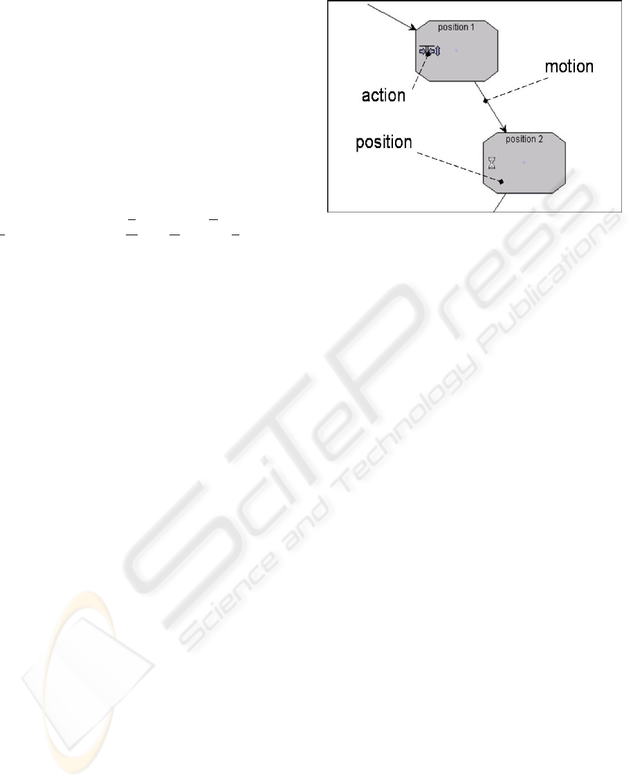
When the endeffector is moved to a certain position,
specific tasks can be fulfilled. These tasks are called
actions. Examples are gripping parts, analyzing
camera data or executing closed-loop fine-
positioning routines. The number of assignable
actions to one motion or one position isn’t limited.
All actions are managed in a kind of library.
Figure 1
illustrates the coherence of positions, motions and
actions.
Figure 1: motion flow in the visual programming system,
consisting of positions, motions and actions
To realize iterations, so called containers are used. A
container groups several motions and positions
together. It has a well-defined starting and exit point.
A fixed number of iterations can be given by the
user, in order to repeat the program part in the
container a defined number of times. Further on
containers fulfil exception handling. Exceptions are
triggered by specific sensor data. The kind of sensor
data that triggers an exception can be defined by the
user. When an exception occurs, the program flow is
interrupted and continued at a well-defined point in
the program code. Concerning robot programming,
it is very important to consider the next movement
of the endeffector after the program is interrupted. A
safe movement has to be done in order to avoid
collisions.
In the visual programming system exceptions are
bound to a container. Every exception triggered in
the container leads to a new entry point where the
program will continue. The exception which is
triggered by the interference is handled. To assist the
user while moving the endeffector out of the danger
zone when reacting on interferences a specific type
of motion can be set. Every exception has a user-
defined name and is declared inside a container.
Exceptions consist of input signals, internal or
external states and interferences. The content of each
exception is defined by the user and depends on the
integrated sensors. To define exceptions logical
expressions and Boolean operators are used.
Figure 2 exemplifies the coherence of containers and
exceptions. The defined starting and exit point of the
container can be seen as well. The number of
iterations is located at the upper left corner of the
container.
ICINCO 2005 - ROBOTICS AND AUTOMATION
108
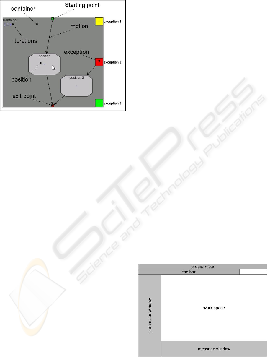
Figure 2: Usage of containers to handle exceptions
A short example points up the meaning: A container
includes two positions which are linked with
motions. To grip a part at the first position the action
grip is assigned to it. At the second position the part
has to be fit in a hole. Thus the action peg in hole is
added to the position. The gripper is equipped with a
force-torque-sensor which detects the interferences
collision during gripping, collision during peg in
hole and collision during motion. Inside the
container two exceptions are declared: assembly
collision and motion collision. One handles the
collision during motion and the other during
gripping and peg in hole. The user combines the two
interferences collision during gripping and collision
during peg in hole with the logical expression or for
the exception assembly collision. If one of these two
interferences occurs the same exception will be
triggered. The reaction is the same in both cases.
Inside a container any exception is allowed. They
are valid for the whole program flow inside the
container. Apart from the definition of exceptions
for the whole container, local exceptions can be
defined. They refer to single positions or motions.
The reaction on the occurrence of exceptions is
defined inside the container as well. Six different
reaction types exist:
– The entire program is aborted.
– The current position including all actions is
repeated.
– The last action is repeated.
– The program flow jumps to the starting point of
the container and starts again.
– The program flow inside the container aborts,
jumps to the exit point of the container and the
next cycle starts.
– The user defines a reaction which includes
positions, motions and actions.
For each reaction type several actions can be added.
To modify the program flow elements can be
shifted, deleted or inserted. The completed program
can be stored in a platform independent format or
translated to a specific robot code. It is possible to
generate several programs for different robots
starting from the same program flow. To run the
program the generated robot code has to be
transferred to robot controller and started.
3 IMPLEMENTATION
To demonstrate the novel concept the tool PRIMOS
is realized. It is developed in the programming
language JAVA. A GUI including the visual
programming surface and the elements of the
concepts is implemented. The GUI is divided into
different areas: program bar, toolbar, work space,
parameter window and message window.
In the program bar all important administration
functions, like save, open or compiling the code to a
specific robot language can be found. The tool bar
includes icons to create the elements container,
position and actions. They can be added to the
program in the work space by drag and drop. Further
on functions to zoom inside the work space are
integrated in the tool bar. The work space includes
the visual programming surface to develop the
programs. Elements of the concept can be shifted,
deleted or inserted. In the parameter window
specific setting can be done. E.g. the reference point
coordinates or the including exceptions and tasks of
a position can be found in the parameter window of
a position. The message window displays errors
during the programming process. E.g. a message
will be shown if a motion is not connected to a
position or a container. In
Figure 3 the screen
segmentation can be seen.
Figure 3: layout of the user interface
PRIMOS – A NOVEL CONCEPT TO PROGRAM COMPLEX ASSEMBLY PROCESSES
109
After completing a program, code for the robot
controller is generated. Before producing
manufacturer-dependent code a syntax and
feasibility check is carried out. Up to now the
compiler for the robot language V
+
from Adept is
realized.
4 VERIFICATION
The prototype of PRIMOS is used to program a
micro assembly process. The goal of the process is
to assemble seven flanges on the end of seven
optical fibre cables which have a diameter of 500
micrometers. One of the main problems is to find
and to position the flange on the maximum of the
coefficient of coupling. For assembling a micro
robot and an intelligent gripper are available. The
intelligent gripper is featured with integrated sensors
to measure gripping width and gripping force. Based
on the sensor data a classification into grip situations
and appropriate interferences is provided. The
programming language of the micro robot controller
is V
+
.
The assembly process can be divided into four steps.
First a flange which is positioned on a magazine has
to be gripped. Then it is positioned between the end
of an optical fibre cable and an analysis unit which
measures the intensity of the passing light.
The goal is to figure out the point coordinates with
the maximum intensity. While the flange is moved
in a definite manner the intensity is continuously
measured. To finish the assembly process the
gripped flange is mounted on an optical fibre cable.
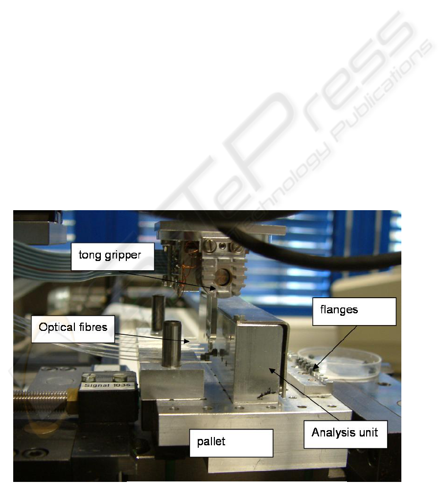
Figure 4 shows the setup of the assembly cell. On
the left side the optical fibres can be seen which are
fixed on a panel. On the right side the magazine with
the unused flanges can be found. In front of the
optical fibres the analysis unit is installed. At the top
of the picture the tong gripper can be seen. The
magazine, the analysis unit and the flanges are
mounted on a pallet which can be seen at the bottom
of the picture.
The assembly process can be interfered in several
ways. The used sensors detect the following ones.
On each detected interference type a specific
reaction takes place.
– If no flange is gripped, the assembly cycle will
be skipped and the next flange will be gripped.
– If a flange gets lost during the assembly process,
the assembly cycle will be skipped and the next
flange will be taken.
– If the flange is gripped incorrectly or
eccentrically, the flange will be aligned on a
specific surface and the assembly cycle is
continued.
– The assembly process will be aborted if a
collision is detected.
Figure 4: assembling flanges on optical fibres
ICINCO 2005 - ROBOTICS AND AUTOMATION
110
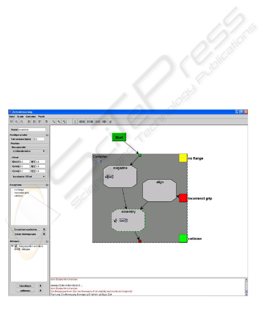
To program the process with PRIMOS a container is
inserted and connected with a motion to the program
start. The container includes two positions and three
motions. The first position is named magazine. It is
parameterized by the point coordinates of the flange
on the magazine. The action grip is added. The
second position is named assembly. It contains the
point coordinates between the cable and the
analyzing unit. The actions maximum finding and
mounting and ungrip are added.
The first motion connects the starting point of the
container and the first position magazine. The
second motion links the two positions magazine and
assembly. The third motion connects the position
assembly with the exit point of the container.
The container includes three exceptions. The first
exception, named no flange threads the situation if
no flange is gripped or a gripped flange gets lost.
The second exception, named incorrect grip handles
incorrectly gripped flanges. The third exception,
named collision covers every kind of collision.
The reaction on no flange is to abort the cycle inside
the container and to start with the next one. On the
occurrence of the exception incorrect grip a user
defined reaction is triggered. The incorrectly gripped
flange is adjusted. Therefore a position align is
inserted in the container. The position contains the
point coordinates of the specific surface where the
flange is aligned. The position align is connected
with motions to the exception and leads to the
position assembly. The reaction on the third
exception collision is the abortion of the entire
program.
The complete GUI of PRIMOS and the program
flow of the whole assembly process in the work
space can be seen in
Figure 5 .
5 CONCLUSION
A novel concept to program sensor based assembly
processes has been presented. The motion flow of
the robot has to be defined by the user, by specifying
the sequence of positions of the endeffector and the
moves of the robot. Hence, it is orientated at the
mental model of the user.
To reduce complexity as well as abstraction and to
improve clarity the programming takes place in a
visual programming environment. The visual
programming provides various advantages compared
to text-orientated programming systems and to
graphic-supported systems. Compared to graphic-
supported simulation systems is no need for a
Figure 5: programming the assembly process with PRIMOS
PRIMOS – A NOVEL CONCEPT TO PROGRAM COMPLEX ASSEMBLY PROCESSES
111

precise and complex environment model. In relation
to text-oriented programming systems an improved
clarity can be achieved.
Furthermore complexity is reduced by using only
five different types of elements to generate the
program: positions, motions, actions, containers and
exceptions.
In particular action elements capsulate and hide
complexity. Additionally action elements deliver the
task orientated character of the concept, because
huge program structures are reduced to self-
configuring modules. An example can be found in
the programming of the presented assembly process.
The action maximum finding and mounting is
available as a module.
The handling of trouble is enabled by the use of
exceptions. They are user defined and any kind of
reaction can be determined. Any detectable
interference by the sensors can be used.
The concept has been successfully implemented in
the tool PRIMOS. Its operability has been tested by
programming an exemplary sensor based assembly
process. Diagnostics and the handling on occurring
interferences have been tested with positive results.
In ongoing researches there are still some aspects to
consider. Up to now merely the manufacture specific
language V
+
is supported. To demonstrate the
platform independent character, additional back ends
are necessary. As yet just a few actions elements are
realized in the prototype. To improve the work
capability further actions like camera analysis have
to be realized.
The prototype does not support the teaching of point
coordinates after generating the code so far. It is
necessary to expand the tool within the next steps by
this requirement.
The new programming concept and the
corresponding programming tool PRIMOS
significantly reduce the complexity of program code
for sensor based assembly processes. The tool offers
a way to implement complex processes focusing
process safety instead of handling the complexity of
the program code.
REFERENCES
Bischoff, R.; Kazi, A.; Seyfarth, M., 2002. The MORPHA
Style Guide for Icon-Based Programming. In Proc. of
the 11th IEEE Int. Workshop on Robot and Human
interactive Communication, ROMAN2002, Berlin,
Germany, September 25-27, pp. 482-487.
Blume, C., Früauf, P., 1996. Standardization of
Programming Methods and Languages for
Manipulation Industrial Robots. In: Proceedings of the
27
th
International Symposium on Industrial Robots, 6.-
8.October 1996, Milan, Italy, page 677-682.
Denkena, B., Wörn, H., Apitz, R., Kowalski, P., Mages,
D., 2004. Vereinfachte Programmierung von
Industrierobotern. In: wt Werkstattstechnik online, page
442-446.
Hirziger, G., 1999. Es gibt noch viel zu tun – Gedanken
zur Entwicklung der Robotik. In: Schweizer
Maschinenmarkt Nr. 26, pp. 94-88.
Krause, F.-L., Uhlmann, E., 1998. Stand und
Entwicklungstendenzen in der Robotertechnik.
München. Carl Hanser Verlag.
Möbius, F., 1996. Visuelle Programmierung von
Industrierobotern: Ein Beitrag zur bedienergerechten
Gestaltung von Programmiersystemen. Düsseldorf,
VDI Verlag.
Rosenbusch, T., 2003: Forschung für die Robotik von
morgen. In: wt Werkstattstechnik online, pp. 638-643.
Schiffer, S., 1998. Visuelle Programmierung –
Grundlagen und Einsatzmöglichkeiten. Bonn. Addison-
Wesley-Longman.
Schröder, C., 2000. Integration von Sensorik in die
visuelle Roboterprogrammierung. Disseration.
Universität Kaiserslautern – Fachbereich
Maschinenbau,
Weck, M., Gottschald, J., 2001: Place & Play-Roboter. In:
wt Werstattstechnik online.
Weck, M., Almeida, C., 2003. Unscharfe Roboter-
Programmierung. In: wt Wertstattstechnik online, pp.
627-631.
Wörn, H., Wurll, C., Henrich, D., 1998. Automatic off-
line programming and motion planning for industrial
robots. In: Proceedings of the 29
th
International
Symposium on Robotics, 27.-30. April 1998,
Birmingham, Great Britain.
Wörn, H., 2003. Tendenzen in der Fabrikautomation. In:
VDI Berichte Nr. 1756.
Zäh, M.F., Vogl, W., Munzert, U., 2004. Beschleunigte
Programmierung von Industrieroboter. In: wt
Werkstattstechnik online , page 438-441.
Zühlke, D., Möbius, F., Schröder, C., 1997: Symbols
facilitate programming of industrial robots. In:
Proceedings of the 1997 IEEE International
Conference on Robotics and Automation, Albuquerque,
New Mexico, pp. 3037-3042.
ICINCO 2005 - ROBOTICS AND AUTOMATION
112
