
DECENTRALIZED SLIDING MODE CONTROL TECHNIQUE
BASED POWER SYSTEM STABILIZER (PSS) FOR
MULTIMACHINE POWER SYSTEM
Vitthal Bandal*, B. Bandyopadhyay**
Research Scholar*, Professor **
System and Control Engineering,IIT Bombay,Powai,Mumbai-400 076 INDIA
A. M. Kulkarni
Associate Professor
Department of Electrical Engineering ,IIT Bombay,Powai,Mumbai-400 076 INDIA
Keywords:
Power system stabilizer, sliding mode control, and multimachine power system.
Abstract:
Power System Stabilizers (PSSs) are added to excitation system to enhance the damping of low frequency
oscillations. In this paper, the design of PSS for multimachine power system (MMPS) using output feedback
sliding mode control is proposed. The non-linear model of a multimachine power system is linearized about an
operating point and the linearized model of the plant is obtained. The output feedback sliding mode controller
is designed and is applied to non-linear plant model of the multimachine power system at that operating
(equilibrium) point. This method does not require the complete states of the system for feedback and is easily
implementable.
1 INTRODUCTION
In recent years considerable efforts have been made
to enhance the dynamic stability (or small perturba-
tion stability) of power systems. Although modern
voltage regulators and excitation systems with fast re-
sponse speeds and high ceiling voltages can be used
to improve the transient stability by increasing the
synchronizing torque of a machine, their effect on
the damping torque is small. In cases where system
may operate with negative damping characteristics,
the voltage regulator usually aggravates the situation
by increasing the negative damping and hence insta-
bility may result in the system (Ramamurthy et al.,
1996),(DeMello et al., 1980).
In order to reduce this undesirable effect and im-
prove the system dynamic performance, it is useful
to introduce supplementary signals to increase the
damping. Several approaches have been reported in
the literature to provide the damping torque required
for improving the dynamic stability. A conventional
power system stabilizer consists of a lead-lag network
using filtered speed or power as input that is used to
generate supplementary signal. In this paper, PSS de-
sign using output feedback sliding mode control tech-
nique has been proposed.
The brief outline of the paper is as follows: Section
2 presents basics of power system stabilizer. Section 3
presents the review on fast output sampling and state
feedback sliding mode control. Section 4 presents
output feedback sliding mode control method; the
same is used for decentralized PSS design of a 10-
machine 39-bus system. The designed controller is
used to perform simulation on a non-linear model of
the multimachine power system, to obtain the system
response against disturbances.
2 POWER SYSTEM STABILIZER
2.1 Basic Concept of conventional
PSS design
The basic function of a power system stabilizer is to
extend stability limits by modulating generator excita-
tion to provide damping to the oscillation of synchro-
nous machine rotors relative to one another. The os-
cillations of concern typically occur in the frequency
range of approximately 0.2 to 3.0 Hz, and insuffi-
cient damping of these oscillations may limit ability
to transmit power. To provide damping, the stabilizer
must produce a component of electrical torque, which
is in phase with the speed changes. The implementa-
tion details differ, depending upon the stabilizer in-
put signal employed. However, for any input signal,
the transfer function of the stabilizer must compensate
for the gain and phase of excitation system, the gen-
161
Bandal V., Bandyopadhyay B. and M. Kulkarni A. (2005).
DECENTRALIZED SLIDING MODE CONTROL TECHNIQUE BASED POWER SYSTEM STABILIZER (PSS) FOR MULTIMACHINE POWER SYSTEM.
In Proceedings of the Second International Conference on Informatics in Control, Automation and Robotics - Signal Processing, Systems Modeling and
Control, pages 161-165
DOI: 10.5220/0001159001610165
Copyright
c
SciTePress
erator and the power system, which collectively de-
termines the transfer function from the stabilizer out-
put to the component of electrical torque which can
be modulated via excitation system (E.V.Larsen and
D.A.Swann, 1981a).
2.2 Classical Stabilizer
implementation procedure
Implementation of a power system stabilizer implies
adjustment of its frequency characteristic and gain to
produce the desired damping of the system oscilla-
tions in the frequency range of 0.2 to 3.0 Hz. The
transfer function of a generic power system stabilizer
may be expressed as
G
p
(s) = K
s
T
w
s (1 + sT
1
) (1 + sT
3
)
(1 + T
w
s) (1 + sT
2
) (1 + sT
4
)
G
f
(s)
where K
s
represents stabilizer gain and G
f
(s) rep-
resents combined transfer function of torsional filter
(if required) and input signal transducer. The stabi-
lizer frequency characteristic is adjusted by varying
the time constant T
w
, T
1
, T
2
, T
3
and T
4
. A torsional
filter may not be necessary with signals like power or
delta-P-omega signal (Kundur, 1993).
A power system stabilizer can be most effectively
applied if it is tuned with an understanding of the as-
sociated power characteristics and the function to be
performed by the stabilizer. Knowledge of the modes
of power system oscillation to which the stabilizer
is to provide damping establishes the range of fre-
quencies over which the stabilizer must operate. Sim-
ple analytical models, such as that of a multimachine
power systems(MMPS), can be useful in determining
the frequencies of local mode oscillations during the
planning stage of a new plant. It is also desirable to
establish the weak power system conditions and asso-
ciated loading for which stable operation is expected,
as the adequacy of the power system stabilizer appli-
cation will be determined under these performance
conditions. Since the limiting gain of the some sta-
bilizers, viz., those having input signal from speed or
power, occurs with a strong transmission system, it
is necessary to establish the strongest credible system
as the “tuning condition” for these stabilizers. Ex-
perience suggest that designing a stabilizer for satis-
factory operation with an external system reactance
ranging from 20% to 80% on the unit rating will en-
sure robust performance (E.V.Larsen and D.A.Swann,
1981b).
2.3 Multi-machine System Analysis
Analysis of practical power system involves the si-
multaneous solution of equations consisting of syn-
chronous machines, associated excitation system,
prime movers, interconnecting transmission network,
static and dynamic ( motor ) loads, and other devices
such as HVDC converters, static var compensator.
The dynamics of the machine rotor circuits, excita-
tion systems, prime mover and other devices are rep-
resented by differential equations. This results in the
complete system model consisting of large number of
ordinary differential and algebraic equations (Kundur,
1993).
2.3.1 Generator Equations
The machine equations ( for j
th
machine ) are
dE
′
q j
dt
=
−1
T
′
d0j
[E
′
q j
− (x
dj
− x
′
dj
)i
dj
− E
fdj
],(1)
dδ
j
dt
= ω
B
(S
mj
− S
mj0
), (2)
dS
mj
dt
=
−1
2H
[D
j
(S
mj
− S
mj0
) − P
mj
+ P
ej
.(3)
Model 1.0 is assumed for synchronous machines
by neglecting the damper windings. In addition,
the following assumptions are made for simplicity
(K.R.Padiyar, 1996).
1. The loads are represented by constant impedances.
2. Transients saliency is ignored by considering x
q
=
x
′
d
.
3. Mechanical power is assumed to be constant.
4. E
fd
is single time constant AVR.
2.3.2 State space model of multimachine system
(Machine model 1.0)
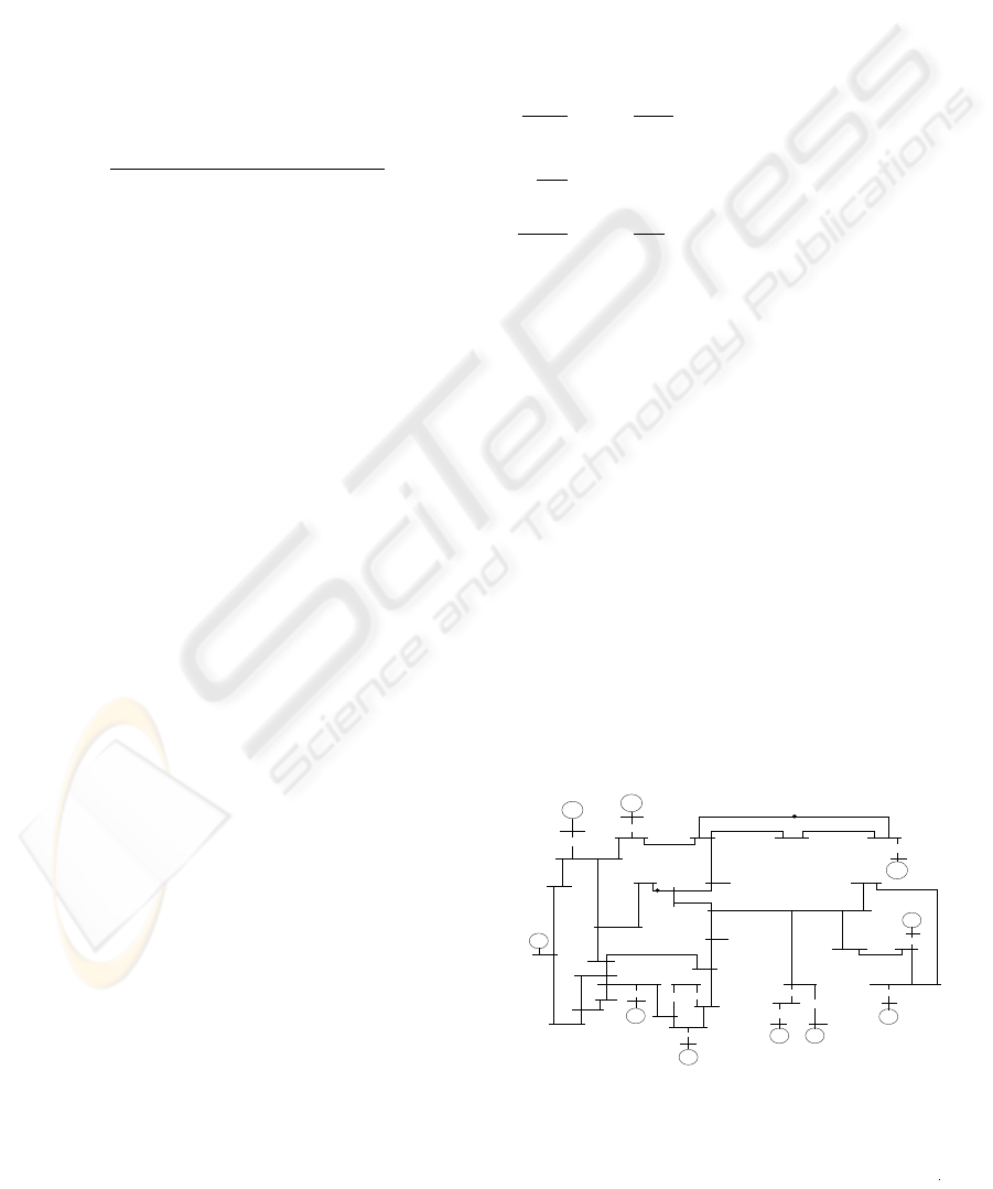
The state space model of a 10-machine 39-bus mul-
timachine power system, the single line diagram of
which is shown in Fig.1 can be obtained using gen-
erator, transformer, network and loadflow data with
variation in generator and network data as given be-
low (K.R.Padiyar, 1996),
26
27
35
8
8
11
12
10
10
2
2
13
14
25
38
17
18
7
7
15
19
4 5
37
16 32
1
1
3
31
34
3
4
20
30
33
5
39
6
9
21
24
28
29
36
22
23
6
9
W
W
W
W
W W
W
W
W
W
W
W
43
42
Figure 1: Single Line Diagram of 10 Machine 39-Bus Sys-
tem
ICINCO 2005 - SIGNAL PROCESSING, SYSTEMS MODELING AND CONTROL
162

.
x
= Ax + B (△V
ref
+ △V
s
) , (4)
y = Cx, (5)
where
x = [x
1,
x
2,
. . . , x
10
]
T
, and y = [y
1,
y
2,
. . . , y
10
]
T
.
x
1
denotes the states of 1
st
machine and are given
as x
1
= [S
m
, δ, Efd, Eq
′
]. Similarly, y
1
denotes
the output of the 1
st
machine and is given as y
1
=
[S
m
, 0, 0, 0].
Where S
m
is machine slip, δ is machine shaft an-
gular displacement in degrees, Efd is generator field
voltage in pu and Eq
′
is voltage proportional to field
flux linkages of machine in pu.
The elements of matrix A are dependent on the op-
erating condition.
3 REVIEW OF FAST OUTPUT
SAMPLING AND STATE
FEEDBACK SLIDING MODE
CONTROL
In the following, fast output sampling feedback tech-
nique and state feedback sliding mode control are
briefly reviewed.
3.1 Fast output sampling feedback
In this technique an output feedback gain is obtained
to realize a discrete state feedback gain by multi-rate
observations of the output signal. The control sig-
nal is held constant during each sampling interval τ
(H.Werner and K.Furuta, 1995).
Consider a SISO plant described by a continuous
time linear model
˙
x = Ax + Bu, (6)
y = Cx.
Where x ∈ R
n
, u ∈ R, y ∈ R and the matrices A,
B and C are of appropriate dimensions.
Let ( Φ
τ
, Γ
τ
, C) be the system given by Eqn.(6)
sampled at sampling interval τ seconds and is repre-
sented as,
x(k + 1) = Φ
τ
x(k) + Γ
τ
u(k), (7)
y(k) = Cx(k). (8)
Also, let ( Φ, Γ, C ) be the system given by Eqn.(6)
sampled at another sampling rate 1/∆ where ∆ =
τ/N . Let, (Φ
τ
, Γ
τ
) and (Φ, C) are assumed to be
controllable and observable, respectively. Let υ de-
note the observability index of ( Φ, C ). N is chosen
to be greater than or equal to υ. The output is mea-
sured at the sampling rate of ∆ and a constant control
signal u(t) is applied over a period during the interval
τ.
Then a representation for the system given by Eqns.
(7) and (8) is
x(k + 1) = Φ
τ
x(k) + Γ
τ
u(k) (9)
y
k+1
= C
0
x(k) + D
0
u(k) (10)
where,
y
k
=
y(kτ − τ )
y(kτ − τ + ∆)
.
y(kτ − ∆)
,
C
0
=
C
CΦ
.
.
CΦ
N−1
, D
0
=
0
CΓ
.
.
C
P
N−2
j=0
Φ
j
Γ
.
3.2 State feedback sliding mode
control
Consider a discretized single input single output
(SISO) system given by Eqns.(9) and (10). The aim
is to make the system states slide along the plane
s(k) = c
T
x(k) = 0 (11)
where c is the switching plane parameter matrix.
This motion is termed as sliding mode. Ideal slid-
ing mode is not possible in discrete systems because
in case of discrete sliding mode, control action can
only be activated at sampling instants and the control
effort is constant over each sampling period. Also
when state reaches the switching surface, the subse-
quent discrete-time switching cannot generate equiv-
alent control to keep the state on the surface. As a
result discrete-time sliding mode can undergo only
quasi-sliding mode motion. It is assumed that the pair
( Φ
τ
, Γτ ) is controllable and the pair ( Φτ, C) is ob-
servable. The reaching law for discrete time sliding
mode is as given by (Gao et al., 1995)
s(k + 1) − s(k) = −qτs(k) − ετsgn(s(k)) (12)
Consider an incremental change in s(k) which is
given as
s(k + 1) − s(k) = c
T
x(k + 1) − c
T
x(k) (13)
= c
T
Φ
τ
x(k) + c
T
Γ
τ
u(k) − c
T
x(k) (14)
DECENTRALIZED SLIDING MODE CONTROL TECHNIQUE BASED POWER SYSTEM STABILIZER (PSS) FOR
MULTIMACHINE POWER SYSTEM
163
Comparing Eqn. (12 ) with Eqn. (14) one obtains
−ετsgn(s(k)) − qτ s (k) =
c
T
Φ
τ
x(k) + c
T
Γ
τ
u(k) − c
T
x(k) (15)
Solving for u(k) gives the state feedback based dis-
crete sliding mode control law as (Gao et al., 1995).
u(k) = F x(k) + γsgn(s(k)) (16)
Where
F = −(c
T
Γ
τ
)
−1
(c
T
Φ
τ
− c
T
I + qτc
T
)
,
γ = −(c
T
Γ
τ
)
−1
ετ (17)
4 OUTPUT FEEDBACK SLIDING
MODE CONTROL
A generalized expression for the state feedback based
discrete sliding mode control has been derived and is
as given by Eqn. (16). Solving Eqn.(9), we get,
x(k) = C
−1
0
y
k
+ (Γ
τ
− Φ
τ
C
−1
0
D
0
)u(k − 1) (18)
Substituting for x(k) from Eqn. (18) in Eqns. (11)
and (16), we get (B.Bandyopadhyay et al., 2004)
s(k) = c
T
Φ
τ
C
−1
0
y
k
(19)
+c
T
[Γ
τ
− Φ
τ
C
−1
0
D
0
]u(k − 1)
,
u(k) = F Φ
τ
C
−1
0
y
k
(20)
+F [Γ
τ
− Φ
τ
C
−1
0
D
0
]u(k − 1)
+γsgn(s(k))
.
Thus, it can be seen from the Eqns. (19) and (20)
that the states of the system are needed neither for
switching function evaluation nor for the feedback
purpose.
5 DECENTRALIZED PSS DESIGN
FOR MULTIMACHINE POWER
SYSTEM(10-MACHINE 39-BUS
SYSTEM) USING OUTPUT
FEEDBACK SLIDING MODE
CONTROL
The nonlinear differential equations governing the
behavior of 10-machine 39-bus system is linearized
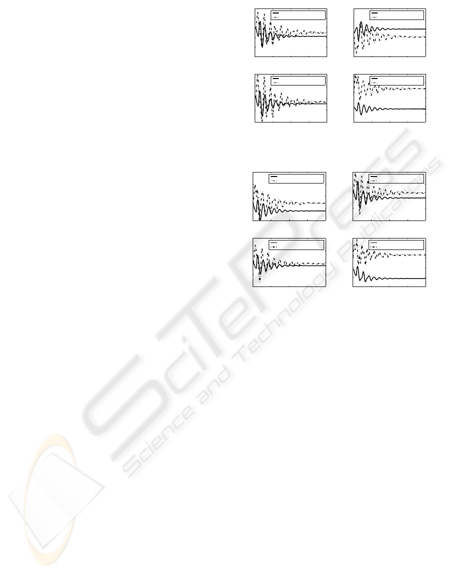
0 5 10 15 20
0.4
0.45
0.5
0.55
0.6
0.65
Time in sec.
Delta
Generator 1
Sliding Mode Control PSS
Classical PSS
0 5 10 15 20
−0.4
−0.35
−0.3
−0.25
−0.2
Time in sec.
Delta
Generator 2
Sliding Mode Control PSS
Classical PSS
0 5 10 15 20
0.5
0.55
0.6
0.65
0.7
Time in sec.
Delta
Generator 3
Sliding Mode Control PSS
Classical PSS
0 5 10 15 20
0.4
0.5
0.6
0.7
0.8
0.9
1
Time in sec.
Delta
Generator 4
Sliding Mode Control PSS
Classical PSS
Figure 2: Nonlinear Simulation ( Rotor angle)
0 5 10 15 20
0.6
0.7
0.8
0.9
1
Time in sec.
Delta
Generator 5
Sliding Mode Control PSS
Classical PSS
0 5 10 15 20
0.3
0.4
0.5
0.6
0.7
Time in sec.
Delta
Generator 6
Sliding Mode Control PSS
Classical PSS
0 5 10 15 20
0.4
0.5
0.6
0.7
0.8
Time in sec.
Delta
Generator 7
Sliding Mode Control PSS
Classical PSS
0 5 10 15 20
0.5
0.6
0.7
0.8
0.9
1
Time in sec.
Delta
Generator 8
Sliding Mode Control PSS
Classical PSS
Figure 3: Nonlinear Simulation ( Rotor angle)
about an operating point to obtain a linear model,
which represents the small signal oscillatory response
of the power system. The single line diagram of the
power system used in analysis is shown in Fig.1.
The above 10-machine 39-bus system was modeled
using MATLAB. The slip of the machine is taken as
output. This output signal with controller output u(k)
and a limiter is added to V
ref
signal and is used to
damp out the small signal disturbances via modulat-
ing the generator excitation. The disturbance consid-
ered is a self clearing fault at bus no. 11 which is
cleared after 0.1 second and the real power of the gen-
erator 1 is 140 % of it’s nominal value. The nonlinear
simulation results of different generators( with clas-
sical PSS and sliding mode controller PSS) for one
model ( i.e. at a particular operating condition) are
shown in Fig. 2 to Fig.7 .
6 CONCLUSION
In this paper, a design scheme of the power system
stabilizer for multimachine power system using out-
put feedback sliding mode control is proposed and
substantiated by simulation results. The slip signal is
taken as an output and output feedback sliding mode
ICINCO 2005 - SIGNAL PROCESSING, SYSTEMS MODELING AND CONTROL
164
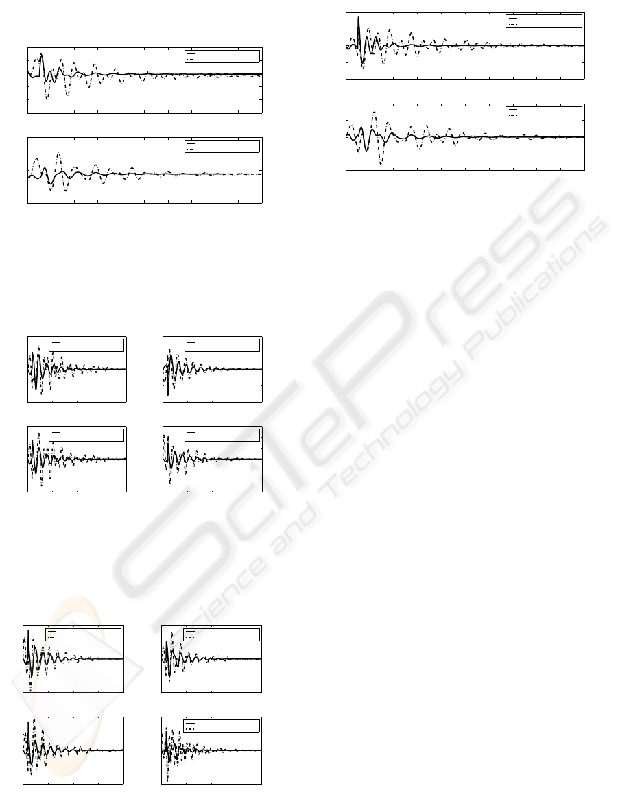
0 2 4 6 8 10 12 14 16 18 20
0.5
0.6
0.7
0.8
0.9
1
Time in sec.
Delta
Generator 9
Sliding Mode Control PSS
Classical PSS
0 2 4 6 8 10 12 14 16 18 20
−0.2
−0.1
0
0.1
0.2
Time in sec.
Delta
Generator 10
Sliding Mode Control PSS
Classical PSS
Figure 4: Nonlinear Simulation ( Rotor angle)
0 5 10 15 20
−1.5
−1
−0.5
0
0.5
1
1.5
x 10
−3
Time in sec.
Slip
Generator 1
Sliding Mode Control PSS
Classical PSS
0 5 10 15 20
−1
−0.5
0
0.5
1
x 10
−3
Time in sec.
Slip
Generator 2
Sliding Mode Control PSS
Classical PSS
0 5 10 15 20
−1.5
−1
−0.5
0
0.5
1
1.5
x 10
−3
Time in sec.
Slip
Generator 3
Sliding Mode Control PSS
Classical PSS
0 5 10 15 20
−3
−2
−1
0
1
2
3
x 10
−3
Time in sec.
Slip
Generator 4
Sliding Mode Control PSS
Classical PSS
Figure 5: Nonlinear Simulation ( Slip)
0 5 10 15 20
−2
−1
0
1
2
x 10
−3
Time in sec.
Slip
Generator 5
Sliding Mode Control PSS
Classical PSS
0 5 10 15 20
−3
−2
−1
0
1
2
3
x 10
−3
Time in sec.
Slip
Generator 6
Sliding Mode Control PSS
Classical PSS
0 5 10 15 20
−2
−1
0
1
2
x 10
−3
Time in sec.
Slip
Generator 7
0 5 10 15 20
−3
−2
−1
0
1
2
3
x 10
−3
Time in sec.
Slip
Generator 8
Sliding Mode Control PSS
Classical PSS
Figure 6: Nonlinear Simulation ( Slip)
0 2 4 6 8 10 12 14 16 18 20
−4
−2
0
2
4
x 10
−3
Time in sec.
Slip
Generator 9
Sliding Mode Control PSS
Classical PSS
0 2 4 6 8 10 12 14 16 18 20
−2
−1
0
1
2
x 10
−3
Time in sec.
Slip
Generator 10
Sliding Mode Control PSS
Classical PSS
Figure 7: Nonlinear Simulation ( Slip)
control is applied at an appropriate sampling rate. It is
found that designed controller provides good damp-
ing enhancement for multimachine power system as
compared with the classical PSS.
REFERENCES
B.Bandyopadhyay, V.K.Thakar, C.M.Saaj, and Janard-
hanan, S. (2004). Algorithm for computing sliding
mode control and switching surface from output sam-
ples. In Proc.8th IEEE Variable Structure Systems
Workshop, page Paper No.4.
DeMello, F., Nolan, P., Laskowski, T., and Undrill, J.
(1980). Co-ordinated application of stabilizers in
multi-machine power systems. IEEE Trans. on Power
Apparatus and Systems, PAS-99:892–901.
E.V.Larsen and D.A.Swann (1981a). Applying power sys-
tem stabilizers part- i: General concepts. IEEE Trans.
on Power Apparatus and Systems, PAS-100(6):3017–
3024.
E.V.Larsen and D.A.Swann (1981b). Applying power sys-
tem stabilizers part- iii: General concepts. IEEE
Trans. on Power Apparatus and Systems, PAS-
100(6):3034–3046.
Gao, W., Wang, Y., and Homaifa, A. (1995). Discrete-time
variable structure control systems. IEEE transactions
on Industrial Electronics, 42(2):117–122.
H.Werner and K.Furuta (1995). Simultaneous stabilization
based on output measurement. Kybernetika, 31:395–
411.
K.R.Padiyar (1996). Power System Dynamics Stability and
Control. Interline publishing private Ltd. Bangalore.
Kundur, P. (1993). Power System Stability and Control.
McGraw-Hill, Inc. Newyork.
Ramamurthy, A. S. R., Parameswaran, S., and Ramar, K.
(1996). Design of decentralized variable structure sta-
bilizers for multimachine power systems. Electrical
Power and Energy Systems, 18(8):535–546.
DECENTRALIZED SLIDING MODE CONTROL TECHNIQUE BASED POWER SYSTEM STABILIZER (PSS) FOR
MULTIMACHINE POWER SYSTEM
165
