
Automatic Evaluation Algorithm for Intersection Hole Cylindrical
Feature in on Machine Measurement Operation
Andri Pratama
1
, Yogi Muldani Hendrawan
1a
, Andini Eka Rahmani
1
, Nizar Miftah Ilyasa
1
,
Herman Budi Harja
1
, Muhammad Udin Harun Al Rasyid
2b
and Idris Winarno
2
1
Department of Manufacturing Engineering Technology, Politeknik Manufaktur Bandung, Dago, Bandung, Indonesia
2
Department of Informatics and Computer Engineering, Politeknik Elektronika Negeri Surabaya, Sukolilo,
Surabaya, Indonesia
Keywords: CAIP, OMM, Feature Recognition, Intersection Cylindrical Feature.
Abstract: This paper discusses an algorithm that can automatically evaluate the intersection hole feature. It takes input
data probe, data reference, data measurement, and ISO 2768 tolerance database to run algorithms on software
which is programmed by the python language. The test model that has the counterbore and countersink
features is tested on an algorithm whose results will then be presented in the form of a standard QC sheet. The
results of OMM measurements will be compared with manual standard measurements to determine the
performance of the algorithm.
1 INTRODUCTION
The manufacturing industry is constantly trying to
meet market demands and satisfy customers. To
realize this, technological developments in the
manufacturing process should be more effective and
efficient. One of them, automation of manufacturing
processes in production process which is not produce
added value directly. This process is a process that
requires time, resources, and capacity but does not
increase product value directly, such as the process of
setting the machine, inspection, and delivery (Abdul
and Musazali, 2020). The inspection process has the
opportunity to make more efficient in manufacturing
process because the inspection process time is depend
on the number of functional dimensions in a product.
By On-Machine Measurement (OMM),
inspection process can be done in CNC machine. So
the workpiece not need to be removed from CNC
machine (Chen et al., 2016; Ding et al., 2020; Huang
et al., 2018; Liu et al., 2015; Mutilba et al., 2017). The
automation inspection process can be developed by
implemented Computer Aided Inspection Planning
(CAIP) on the On-Machine Measurement (OMM)
system (Chung, 1999). It is an integrated process that
a
https://orcid.org/0000-0003-4774-4966
b
https://orcid.org/0000-0002-4473-2364
involves designing, machining, and inspecting the
manufacturing process to measure products directly
at the machine. While CAIP is a product modelling
system that can describe the need for intelligent
geometry and dimension measurements. CAIP is
divided into four stages, face detection, feature
reconstruction, inspection planning, and inspection
code generated (Hendrawan et al, 2014). Thus, CAIP
and OMM are a combination that allows the OMM
method to automate and integrate the inspection
process. In conducting OMM inspections, which
requires feature properties information from the
extracted feature reconstruction phase (Hendrawan et
al, 2021) as input inspection code generated.
After the measurement which is using the OMM
method has been successfully generated (Hendrawan
et al., 2021), the next step is to compare the data from
the initial two-stage output on the CAIP and the
results of the OMM measurement. This activity is
called post CAIP which will give a GO or NO GO
decision on the condition of the hole that has been
made. This paper focuses on intersection hole
cylindrical feature such as the counterbore and
countersink features which are often found in
manufactured products or fasteners application,
especially.
Pratama, A., Hendrawan, Y., Rahmani, A., Ilyasa, N., Harja, H., Al Rasyid, M. and Winarno, I.
Automatic Evaluation Algorithm for Intersection Hole Cylindrical Feature in on Machine Measurement Operation.
DOI: 10.5220/0012037100003575
In Proceedings of the 5th International Conference on Applied Science and Technology on Engineering Science (iCAST-ES 2022), pages 1023-1029
ISBN: 978-989-758-619-4; ISSN: 2975-8246
Copyright © 2023 by SCITEPRESS – Science and Technology Publications, Lda. Under CC license (CC BY-NC-ND 4.0)
1023

2 HOLE PROPERTIES
EVALUATION
This algorithm focuses on the double hole feature
including counterbore and countersink. The
dimension parameters of the size and position of the
two features that will be evaluated by this algorithm.
Therefore, information about the feature properties of
the hole is needed.
2.1 Counterbore Properties
Detailed counterbore feature properties information
will be shown in the image below.
Figure 1: Countersink properties. Source: (Hendrawan et al,
2021).
Basically, counterbore consists of two single hole
features that are on the same axis, namely the blind
hole and the through hole, each of which has diameter
and depth information as shown in Fig. 1. Di1, Di2,
Cpi, Li, di1, di2, Ci1, and Ci2 are top circular
diameter, bottom circular diameter, centre point, line
axis, top depth, bottom depth, top cylindrica, and
bottom cylindrical in i
th
feature, respectively.
To evaluate this counterbore feature requires the
condition that D
i1
>D
i2
and di1 as the depth evaluated
from the inbus bolt head that becomes the
counterbore hole pair. CPi will only be represented
by CPx and CPy coordinates. The counterbore feature
information that needed for evaluation is D
i1
, D
i2
, d
i1
,
CPx and CPy.
2.2 Countersink Properties
Detailed feature properties information of
countersink will be shown in the image below.
Figure 2: Counterbore properties. Source: (Hendrawan et
al, 2021).
Countersink consists of a tapered hole and
through hole that are on the same axis. The built
tapered feature consists of the upper diameter, bottom
diameter, and depth are represented by D
oi1
, D
oi2
, and
d
i1,
respectively with the provisions of D
oi1
> D
oi2
which can form an αi angle with the following
formula.
α
i
= tan
-1
(
)
(1)
di1 =
(2)
Where αi = 45º is set according to the standard.
CPi is represented as CPx dan CPy. The countersink
feature information that needed for evaluation is D
oi2
,
d
i1
, CPx, and CPy.
3 MEASUREMENT METHODS
To evaluate based on the feature properties that have
been defined, a measurement cycle method is needed,
namely the diameter measurement cycle and the
depth measurement cycle.
3.1 Hole Measurement Cycle
In taking measurements by On Machine
Measurement on the hole cylindrical feature, a hole
measurement cycle is required which is stated as
follows.
α
i
iCAST-ES 2022 - International Conference on Applied Science and Technology on Engineering Science
1024
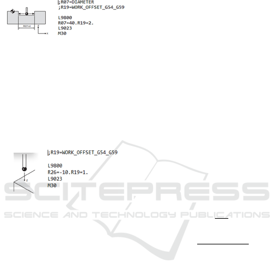
Figure 3: Measure hole illustration. Source: (Renishaw,
2014).
After the hole measurement cycle is executed by a
machine that has installed a probe interface and
PRIMO™ system from RENISHAW, measurement
results in the form of diameter and centre points of the
hole (X and Y) can be produced.
3.2 Depth Measurement Cycle
In addition to the hole measurement cycle, a depth
measurement cycle is needed to complete the
measurements on the hole cylindrical feature. The
depth measurement cycle is expressed as follows.
Figure 4: Measure depth illustration Source: (Renishaw,
2014).
Results in the form of depth in the hole can be
produced After the depth measurement cycle is
executed by the machine that has installed the probe
interface and primo™ system from RENISHAW.
4 AUTOMATIC HOLE
EVALUATION
To complement the previously proposed hole
evaluation module which is only for single-hole
features, a hole evaluation module was added to
evaluate the double hole feature which certainly
enhances the four stages already implemented.
4.1 Inspection Code Generator
With the definition of the cycle to be used as well as
the planning of the probe path that has been
generated. So an inspection code generator was
formed in accordance with existing standards.
Therefore, the measurement touching points
information is needed. To define touching points on
the counterbore, Eq. (3) is used as follows:
𝑡𝑝
𝑐𝑝
Ø𝑝𝑟𝑜𝑏𝑒
(3)
a. Touching points for measuring diameter pilot hole
counterbore:
𝑡𝑝
𝑐𝑝
1.3 𝑑
(4)
b. Touching points for measuring counterbore depth:
In defining touching points for measuring depth.
It takes a shift in the centre point (X) expressed as
follows.
- If the center1_cbn value is positive
𝑚𝑜𝑣𝑒_𝑐𝑒𝑛𝑡𝑒𝑟 𝑐𝑝
𝑟 𝑐𝑝
0.05
(5)
- If the center1_cbn value is negative
𝑚𝑜𝑣𝑒_𝑐𝑒𝑛𝑡𝑒𝑟 𝑐𝑝
𝑟 𝑐𝑝
0.05
(6)
After the central point shift value (X) is generated,
the next step is to execute the cycle for depth
measurement.
Meanwhile, the measurement touching points is
defined to measure countersink. The presence of
differences due to the profile in this type of hole is
oblique. Thus, it can be concluded that the touching
point for depth measurement cannot be carried out
and replaced to make the countersink Ø measurement
which is stated as follows.
ℎ𝑦𝑝𝑜𝑡𝑒𝑛𝑜𝑢𝑠𝑒
(7)
𝑡𝑝_𝑝𝑟𝑜𝑏𝑒 𝑐𝑝
3
(8)
𝑛𝑒𝑤_ℎ𝑦𝑝𝑜
_
(9)
𝑑𝑒𝑣𝑖𝑎𝑡𝑖𝑜𝑛_𝑛𝑒𝑤 𝑡𝑝_𝑝𝑟𝑜𝑏𝑒 𝑛𝑒𝑤_ℎ𝑦𝑝𝑜
(10)
𝑡𝑝
𝑑𝑒𝑣𝑖𝑎𝑡𝑖𝑜𝑛_𝑛𝑒𝑤 𝑡𝑝_𝑝𝑟𝑜𝑏𝑒
(11)
After the measurement for the Ø countersink is
carried out, the next step is to measure the Ø pilot hole
on the countersink by below equation.
𝑡𝑝
𝑐𝑝
1.3 𝑑
(12)
4.2 Hole Evaluation Module
By calculating the difference value between the
feature properties data which is created by the
previously algorithm to evaluate the single hole
feature, and feature properties information from the
double hole which is added with measurement result
data that becomes increased depending on their
respective features. For this reason, probe path data,
Automatic Evaluation Algorithm for Intersection Hole Cylindrical Feature in on Machine Measurement Operation
1025
feature properties data, measurement data that has
been added, and ISO 2768 tolerance data are needed.
Due to the limitations of the measurement method,
the depth of the countersink feature can be calculated
using Eq. (1). The difference in evaluation for each
parameter entering the tolerance area will be given a
GO decision while the difference outside the
tolerance area will be given a NO GO decision.
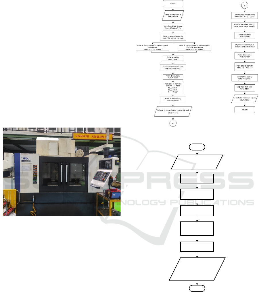
5 EXPERIMENT
To prove that the proposed algorithm can be applied,
the algorithm was tested at the Hyundai WIA F510M
Vertical Machining Centre with a SIEMENS 828D
controller as shown in Fig. 5 and a measurement tool
the 3D probe RENISHAW PRIMO to conduct
experiments.
Figure 5: VMC Hundyai WIA f510M.
The machines used have travel axes of X 1060 mm,
Y 635 mm, Z 635 mm, and table dimensions of 1200
mm x 500 mm, respectively. The 3D diameter size of
the Renishaw PRIMO probe selected is 6mm to take
measurements at the inspection stage of the code
generator. The measurement results will be directly
tested on proposed software that has been embedded
with an evaluation module programmed using the
Python language.
Figure 6: Inspection code algorithm.
Start
• Probe path file (.txt)
• Reference file (.txt)
• Measurement file (.txt)
• ISO 2768
Find x and y coordinates
from probe path file
Find feature parameteres
from reference file base on
x,y probe path coordinates
Find feature parameteres
from measurement file
(R parameter format)
Calculate the difference of
nominal parameters between
reference and measurement
file
Check the difference to the
tolerance zone
• Decision GO for the
parameters that enter
the tolerance zone
• Decision NO GO for
the parameters that out
of the tolerance zone
End
Figure 7: Hole evaluation algorithm.
5.1 Experimental Scenario
The G-Code generated at the inspection stage of the
generator code will be tested on a workpiece that
features an M12 counterbore with details of the upper
diameter of 20 mm, a lower diameter of 13.5 mm, and
a depth of 12.8 mm as well as an M10 countersink
hole with details of a lower diameter of 11 mm, a
iCAST-ES 2022 - International Conference on Applied Science and Technology on Engineering Science
1026

depth of 5.7 mm, and an angle of 45 degrees as shown
in Fig.8.
Figure 8: Product specimen.
The error results from the measurements will be
compared to the medium tolerance range listed in ISO
2768 automatically. The results of the evaluation will
be listed in a standard QC sheet format. To validate
the measurement results directly on the machine,
standard manual measurements were carried out
using a vernier calliper with a precision of 0.02 mm
because the evaluation was still based on moderate
tolerances.
5.2 Experimental Result
The evaluation results are listed as shown with the full
information listed in the table.
Figure 9: Holes Evaluator interface.
It was found that counterbores 1 and 2 with actual
sizes and positions respectively are the upper
diameters of 20.035 mm and 19.985 mm, the lower
diameters of 13.339 mm and 13.350 mm, the depths
of 12.811 mm and 12.821 mm, the X coordinates of
14.996 mm and -14.966 mm, and finally the Y
coordinates of 0.048 mm and 0.010 mm. For other
features, countersinks 1, 2, 3, and 4 respectively
obtained bottom diameters of 11,046 mm, 10.961
mm, 11.045 mm, and 11.032 mm, depths of 5,662
mm, 5,702 mm, 5,668 mm, and 5,672 mm, X
coordinates 34.994 mm, 34.968 mm, -34.991 mm,
and -34.994 mm, and finally coordinates Y -30.000
mm, 29.995 mm, 30.008 mm, and -29.986 mm. The
differences from the counterbore features are the
upper diameters of 0.035 and -0.014, the lower
diameters of -0.160 mm and -0.149 mm, the depths of
0.011 mm and 0.021 mm., the X coordinates -0.003
mm and 0.033 mm, and the Y coordinates 0.0487 mm
and 0.010 mm. The differences for the countersink
feature were obtained successively, namely the lower
diameters of 0.046 mm, -0.038 mm, 0.045 mm, and
0.032 mm, depths -0.038 mm, 0.002 mm, -0.032 mm,
and -0.028 mm, X coordinates -0.005 mm, -0.031
mm, 0.008 mm, and 0.005 mm, as well as coordinates
Y -0.0009 mm, -0.004 mm, 0.008 mm, and 0.013 mm.
All parameters evaluated for both the counterbore and
countersink features are categorized GO because they
fall within the tolerance range.
The second experiment is to validate the
measurement results on the machine by a vernier
calliper to evaluate all parameters evaluated in on-
machine measurement. The difference results for the
counterbore feature were obtained respectively,
namely the upper diameters of 0.04 mm and -0.016
mm, the lower diameters of -0.156 mm and -0.16 mm,
depths of -0.012 mm and -0.004 mm, X coordinates -
0.002 mm and 0.032 mm, and coordinates of Y -0.014
mm and -0.004 mm. For the countersink feature
obtained successively, namely the lower diameters of
0.008 mm, -0.044 mm, 0 mm, and 0.004 mm, depths
of 0.05 mm, 0.06 mm, 0.03 mm, and 0.02 mm, X
coordinates 0 mm, -0.026 mm, 0.02 mm, and 0.018,
and finally coordinate Y -0.06 mm, -0.014 mm, -
0.044 mm, and -0.004 mm. All parameters evaluated
by using the calliper are categorized GO because they
fall within the tolerance range as shown in table 1
and 2.
When viewed from the experiments of the hole
evaluation algorithm automatically and measuring it
manually, both show the same decision results,
namely GO for all the parameters evaluated. This
means that the proposed algorithm has proven to be
correct in providing decisions by comparing the
results of measurements manually using calipers.
Countersin
k
Counterbore
Automatic Evaluation Algorithm for Intersection Hole Cylindrical Feature in on Machine Measurement Operation
1027

6 CONCLUSIONS
The proposed algorithm already evaluates the
counterbore and countersink features. The proposed
algorithm is developed and implemented in software
programmed using the Python language. Experiments
are needed to test the performance of the algorithm.
The software created requires probe path data, feature
properties data as a reference, measurement data on
the machine, and ISO 2768 tolerance database as
input data. The parameters evaluated are the upper
diameter, lower diameter, depth, x coordinate, and y
coordinate of the counterbore feature as well as the
lower diameter, depth, X coordinate, and Y
coordinate of the countersink feature. The evaluation
results are displayed in a standard QC sheet format.
Based on the experiments that have been carried out,
the algorithm can already work properly.
Figure 10: Automatic hole evaluation result (mm).
ACKNOWLEDGEMENTS
This work was supported by the Ministry of Culture,
Education, Research, and Technology of the Republic
of Indonesia. We would like to thank them for the
support.
Figure 11: Manual hole evaluation result.
REFERENCES
Abdul Rasib, A.H., Musazali, M. (2020). Undestanding of
Non-Value Added Overtime in Manufacturing
Operations. In IOP Conference Series: Material Science
and Engineering. doi: 10.1088/1757-899X/994/1/01
2004
Chung, S.C. (1999). CAD/CAM Integration of on-the-
machine measuring and inspection system for free
formed surfaces. Proceedings of American Society for
Precision Engineering, vol.20, pp 267-270.
Hendrawan, Y.M., Yuwana, M.Y., and Raharno, S. (2014).
Development of computer aided inspection planning
(CAIP) application in on machine measurement
operation (OMM) operations for box primitive features:
Generating inspection codes. In Applied Mechanics and
Materials, vol 660, pp.889-893.
Chen, Y. L., Cai, Y., Shimizu, Y., Ito, S., Gao, W., & Ju, B.
F. (2016). On-machine measurement of microtool wear
and cutting edge chipping by using a diamond edge
artifact. Precision Engineering, 43, 462–467.
https://doi.org/10.1016/j.precisioneng.2015.09.011
Ding, D., Zhao, Z., Zhang, X., Fu, Y., & Xu, J. (2020).
Evaluation and compensation of laser-based on-
machine measurement for inclined and curved profiles.
Measurement, 151, 107236. https://doi.org/
10.1016/j.measurement.2019.107236
No Feature Std Tol Result Error Status
20.0 0.2 20.0354 0.0354 GO
13.5 0.2 13.3395 -0.1605 GO
12.8 0.2 12.8112 0.0112 GO
X 15.0 0.2 14.9967 -0.033 GO
Y 0.0 0.1 0.0106 0.04875 GO
20.0 0.2 19.9853 -0.0147 GO
13.5 0.2 13.3503 -0.1497 GO
12.8 0.2 12.8212 0.0212 GO
X -15.0 0.2 -14.96605 0.03395 GO
Y 0.0 0.1 0.0106 0.0106 GO
11.0 0.2 11.046 0.046 GO
5.7 0.1 5.662 -0.038 GO
X 35.0 0.3 34.9943 -0.0057 GO
Y -30.0 0.2 -30.00095 -0.00095 GO
11.0 0.2 10.9614 -0.0386 GO
5.7 0.1 5.702 0.002 GO
X 35.0 0.3 34.9681 0.0319 GO
Y 30.0 0.2 29.9955 -0.0045 GO
11.0 0.2 11.0453 0.0453 GO
5.7 0.1 5.668 -0.032 GO
X -35.0 0.3 -34.99135 0.00865 GO
Y 30.0 0.2 30.008 0.008 GO
11.0 0.2 11.0323 0.0323 GO
5.7 0.1 5.672 0.0319 GO
X -35.0 0.3 -34.99465 0.00535 GO
Y -30.0 0.2 -29.9867 0.0133 GO
Dl 11
De 5.7
Dim
Du 20
Dl 13.5
De 12.8
Du 20
Dl 13.5
CP
CB1
CB2
CS1
CS2
CS3
De 12.8
Dl 11
De 5.7
Dl 11
6
CP
CP
CP
CP
CP
CS4
De 5.7
Dl 11
De 5.7
1
2
3
4
5
No Feature Std Tol Result Error Status
20.0 0.2 20.004 0.004 GO
13.5 0.2 13.344 -0.156 GO
12.8 0.2 12.788 0.012 GO
X 15.0 0.2 14.998 -0.002 GO
Y 0.0 0.1 -0,014 -0.014 GO
20.0 0.2 19.984 -0.016 GO
13.5 0.2 13.34 -0.16 GO
12.8 0.2 12.796 -0.004 GO
X -15.0 0.2 -14.968 0.032 GO
Y 0.0 0.1 -0.004 -0.004 GO
11.0 0.2 11.008 0.008 GO
5.7 0.1 5.75 0.05 GO
X 35.0 0.3 35.0 0.0 GO
Y -30.0 0.2 -30.06 -0.06 GO
11.0 0.2 10.956 -0.044 GO
5.7 0.1 5.76 0.06 GO
X 35.0 0.3 34.974 -0.026 GO
Y 30.0 0.2 29.986 -0.014 GO
11.0 0.2 11.0 0.0 GO
5.7 0.1 5.73 0.03 GO
X -35.0 0.3 -34.98 0.02 GO
Y 30.0 0.2 29.956 -0.044 GO
11.0 0.2 11.004 0.004 GO
5.7 0.1 5.72 0.02 GO
X -35.0 0.3 -34.982 0.018 GO
Y -30.0 0.2 -29.998 0.002 GO
Dim
Du 20
Dl 13.5
De 12.8
Du 20
Dl 13.5
5 CS3
CP
6 CS4
CP
Dl 11
Dl 11
De 5.7
De 5.7
3 CS1
CP
4 CS2
CP
Dl 11
De 5.7
Dl 11
De 5.7
1CB1
CP
2 CB2
CP
De 12.8
iCAST-ES 2022 - International Conference on Applied Science and Technology on Engineering Science
1028

Huang, N., Yin, C., Liang, L., Hu, J., & Wu, S. (2018).
Error compensation for machining of large thin-walled
part with sculptured surface based on on-machine
measurement. International Journal of Advanced
Manufacturing Technology, 96(9–12), 4345–4352.
https://doi.org/10.1007/s00170-018-1897-x
Liu, H. B., Wang, Y. Q., Jia, Z. Y., & Guo, D. M. (2015).
Integration strategy of on-machine measurement
(OMM) and numerical control (NC) machining for the
large thin-walled parts with surface correlative
constraint. International Journal of Advanced
Manufacturing Technology, 80(9–12), 1721–1731.
https://doi.org/10.1007/s00170-015-7046-x
Hendrawan, Y.M., Muttaqin, R., Pratama, A., Budi Harja,
H., Udin, M., al Rasyid, H., & Winarno, I. (2021).
Intersection Cylindrical Feature Recognition
Algorithm for Counterbore and Countersink Geometry
Application.
Hendrawan, Y.M., Pratama, A., Budi Harja, H., Udin, M.,
al Rasyid, H., & Winarno, I. (2021). Inspection Code
Generator for Hole Cylindrical Feature Evaluation in
On-Machine Measurement Process for Computer
Aided Inspection Planning.
Mutilba, U., Gomez-Acedo, E., Kortaberria, G., Olarra, A.,
& Yagüe-Fabra, J. A. (2017). Traceability of on-
machine tool measurement: A review. In Sensors
(Switzerland) (Vol. 17, Issue 7). MDPI AG.
https://doi.org/10.3390/s17071605
Renishaw. (2014). “Easyprobe cycle for machining center,”
Programming Guide, no, H-2000-6294-00-B
Automatic Evaluation Algorithm for Intersection Hole Cylindrical Feature in on Machine Measurement Operation
1029
